Rigol DM3058 Use and care manual

RIGOL
Calibration Guide
DM3058/DM3058E
Digital Multimeter
Feb. 2015
RIGOL Technologies, Inc.


RIGOL
DM3058/DM3058E Calibration Guide
I
Guaranty and Declaration
Copyright
© 2014 RIGOL Technologies, Inc. All Rights Reserved.
Trademark Information
RIGOL is a registered trademark of RIGOL Technologies, Inc.
Publication Number
CGC03101-1110
Notices
RIGOL products are covered by P.R.C. and foreign patents, issued and pending.
RIGOL reserves the right to modify or change parts of or all the specifications
and pricing policies at company’s sole decision.
Information in this publication replaces all previously corresponding material.
Information in this publication is subject to change without notice.
RIGOL shall not be liable for either incidental or consequential losses in
connection with the furnishing, use or performance of this manual as well as any
information contained.
Any part of this document is forbidden to be copied, photocopied or rearranged
without prior written approval of RIGOL.
Product Certification
RIGOL guarantees this product conforms to the national and industrial standards in
China as well as the ISO9001:2008 standard and the ISO14001:2004 standard. Other
international standard conformance certification is in progress.
Contact Us
If you have any problem or requirement when using our products or this manual,
please contact RIGOL.
E-mail: service@rigol.com
Website: www.rigol.com

RIGOL
DM3058/DM3058E Calibration Guide
II
Safety Requirement
General Safety Summary
Please review the following safety precautions carefully before putting the instrument
into operation so as to avoid any personal injury or damage to the instrument and any
product connected to it. To prevent potential hazards, please use the instrument only
specified by this manual.
Use Proper Power Cord.
Only the power cord designed for the instrument and authorized for use within the
local country could be used.
Ground the Instrument.
The instrument is grounded through the Protective Earth lead of the power cord. To
avoid electric shock, it is essential to connect the earth terminal of the power cord to
the Protective Earth terminal before connecting any inputs or outputs.
Connect the Probe Correctly.
If a probe is used, do not connect the ground lead to high voltage since it has isobaric
electric potential as the ground.
Observe All Terminal Ratings.
To avoid fire or shock hazard, observe all ratings and markers on the instrument and
check your manual for more information about ratings before connecting the
instrument.
Use Proper Overvoltage Protection.
Make sure that no overvoltage (such as that caused by a thunderstorm) can reach the
product, or else the operator might be exposed to the danger of electrical shock.
Do Not Operate Without Covers.
Do not operate the instrument with covers or panels removed.
Do Not Insert Anything Into the Holes of Fan.
Do not insert anything into the holes of the fan to avoid damaging the instrument.
Use Proper Fuse.
Please use the specified fuses.
Avoid Circuit or Wire Exposure.
Do not touch exposed junctions and components when the unit is powered.
Do Not Operate With Suspected Failures.
If you suspect damage occurs to the instrument, have it inspected by RIGOL

RIGOL
DM3058/DM3058E Calibration Guide
III
authorized personnel before further operations. Any maintenance, adjustment or
replacement especially to circuits or accessories must be performed by RIGOL
authorized personnel.
Keep Well Ventilation.
Inadequate ventilation may cause an increase of instrument temperature which would
cause damage to the instrument. So please keep the instrument well ventilated and
inspect the intake and fan regularly.
Do Not Operate in Wet Conditions.
In order to avoid short circuiting to the interior of the device or electric shock, please
do not operate the instrument in a humid environment.
Do Not Operate in an Explosive Atmosphere.
In order to avoid damage to the device or personal injuries, it is important to operate
the device away from an explosive atmosphere.
Keep Product Surfaces Clean and Dry.
To avoid the influence of dust and/or moisture in the air, please keep the surface of the
device clean and dry.
Electrostatic Prevention.
Operate the instrument in an electrostatic discharge protective environment to avoid
damage induced by static discharges. Always ground both the internal and external
conductors of cables to release static before making connections.
Proper Use of Battery.
If a battery is supplied, it must not be exposed to high temperature or in contact with
fire. Keep it out of the reach of children. Improper change of battery (note: lithium
battery) may cause explosion. Use RIGOL specified battery only.
Handling Safety.
Please handle with care during transportation to avoid damage to buttons, knob
interfaces and other parts on the panels.
RIGOL
DM3058/DM3058E Calibration Guide
IV
Safety Terms and Symbols
Terms Used in this Manual. These terms may appear in this manual:
WARNING
Warning statements indicate conditions or practices that could result in
injury or loss of life.
CAUTION
Caution statements indicate conditions or practices that could result in
damage to this product or other property.
Terms Used on the Product. These terms may appear on the product:
DANGER
It calls attention to an operation, if not correctly performed, could
result in injury or hazard immediately.
WARNING
It calls attention to an operation, if not correctly performed, could
result in
potential injury or hazard.
CAUTION
It calls attention to an operation, if not correctly performed, could
result in damage to the product or other devices connected to the
product.
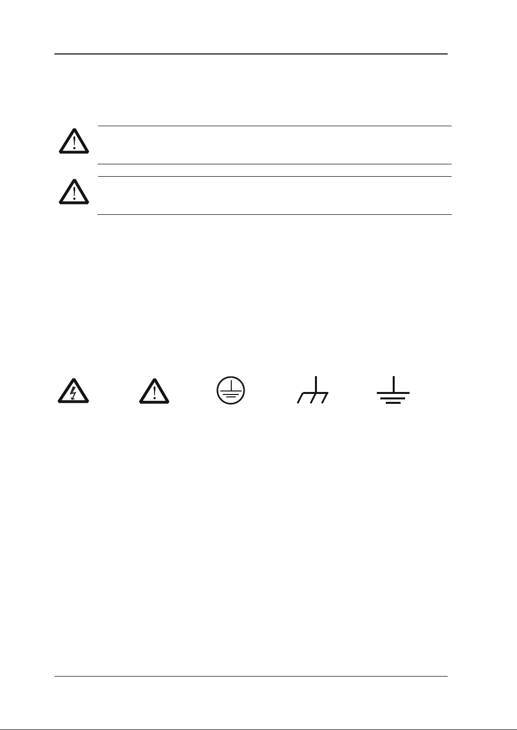
Symbols Used on the Product. These symbols may appear on the product:
Hazardous
Voltage
Safety
Warning
Protective
Earth
Terminal
Chassis
Ground
Test
Ground

RIGOL
DM3058/DM3058E Calibration Guide
V
Allgemeine Sicherheits Informationen
Überprüfen Sie diefolgenden Sicherheitshinweise
sorgfältigumPersonenschädenoderSchäden am Gerätundan damit verbundenen
weiteren Gerätenzu vermeiden. Zur Vermeidung vonGefahren, nutzen Sie bitte das
Gerät nur so, wiein diesem Handbuchangegeben.
Um Feuer oder Verletzungen zu vermeiden, verwenden Sie ein
ordnungsgemäßes Netzkabel.
Verwenden Sie für dieses Gerät nur das für ihr Land zugelassene und genehmigte
Netzkabel.
Erden des Gerätes.
Das Gerät ist durch den Schutzleiter im Netzkabel geerdet. Um Gefahren durch
elektrischen Schlag zu vermeiden, ist es unerlässlich, die Erdung durchzuführen. Erst
dann dürfen weitere Ein- oder Ausgänge verbunden werden.
Anschluss einesTastkopfes.
Die Erdungsklemmen der Sonden sindauf dem gleichen Spannungspegel des
Instruments geerdet. SchließenSie die Erdungsklemmen an keine hohe Spannung an.
Beachten Sie alle Anschlüsse.
Zur Vermeidung von Feuer oder Stromschlag, beachten Sie alle Bemerkungen und
Markierungen auf dem Instrument. Befolgen Sie die Bedienungsanleitung für weitere
Informationen, bevor Sie weitere Anschlüsse an das Instrument legen.
Verwenden Sie einen geeigneten Überspannungsschutz.
Stellen Sie sicher, daß keinerlei Überspannung (wie z.B. durch Gewitter verursacht)
das Gerät erreichen kann. Andernfallsbestehtfür den Anwender die
GefahreinesStromschlages.
Nicht ohne Abdeckung einschalten.
Betreiben Sie das Gerät nicht mit entfernten Gehäuse-Abdeckungen.
Betreiben Sie das Gerät nicht geöffnet.
Der Betrieb mit offenen oder entfernten Gehäuseteilen ist nicht zulässig. Nichts in
entsprechende Öffnungen stecken (Lüfter z.B.)
Passende Sicherung verwenden.
Setzen Sie nur die spezifikationsgemäßen Sicherungen ein.
Vermeiden Sie ungeschützte Verbindungen.
Berühren Sie keine unisolierten Verbindungen oder Baugruppen, während das Gerät in
Betrieb ist.

RIGOL
DM3058/DM3058E Calibration Guide
VI
Betreiben Sie das Gerät nicht im Fehlerfall.
Wenn Sie am Gerät einen Defekt vermuten, sorgen Sie dafür, bevor Sie das Gerät
wieder betreiben, dass eine Untersuchung durch RIGOL autorisiertem Personal
durchgeführt wird. Jedwede Wartung, Einstellarbeiten oder Austausch von Teilen am
Gerät, sowie am Zubehör dürfen nur von RIGOL autorisiertem Personal durchgeführt
werden.
Belüftung sicherstellen.
Unzureichende Belüftung kann zu Temperaturanstiegen und somit zu thermischen
Schäden am Gerät führen. Stellen Sie deswegen die Belüftung sicher und kontrollieren
regelmäßig Lüfter und Belüftungsöffnungen.
Nicht in feuchter Umgebung betreiben.
Zur Vermeidung von Kurzschluß im Geräteinneren und Stromschlag betreiben Sie das
Gerät bitte niemals in feuchter Umgebung.
Nicht in explosiver Atmosphäre betreiben.
Zur Vermeidung von Personen- und Sachschäden ist es unumgänglich, das Gerät
ausschließlich fernab jedweder explosiven Atmosphäre zu betreiben.
Geräteoberflächen sauber und trocken halten.
Um den Einfluß von Staub und Feuchtigkeit aus der Luft auszuschließen, halten Sie
bitte die Geräteoberflächen sauber und trocken.
Schutz gegen elektrostatische Entladung (ESD).
Sorgen Sie für eine elektrostatisch geschützte Umgebung, um somit Schäden und
Funktionsstörungen durch ESD zu vermeiden. Erden Sie vor dem Anschluß immer
Innen- und Außenleiter der Verbindungsleitung, um statische Aufladung zu entladen.
Die richtige Verwendung desAkku.
Wenneine Batterieverwendet wird, vermeiden Sie hohe Temperaturen bzw. Feuer
ausgesetzt werden. Bewahren Sie es außerhalbder Reichweitevon Kindern auf.
UnsachgemäßeÄnderung derBatterie (Anmerkung: Lithium-Batterie) kann zu einer
Explosion führen. VerwendenSie nur von RIGOLangegebenenAkkus.
Sicherer Transport.
Transportieren Sie das Gerät sorgfältig (Verpackung!), um Schäden an
Bedienelementen, Anschlüssen und anderen Teilen zu vermeiden.

RIGOL
DM3058/DM3058E Calibration Guide
VII
Sicherheits Begriffe und Symbole
Begriffe in diesem Guide. Diese Begriffe können in diesem Handbuch auftauchen:
WARNING
Die Kennzeichnung WARNING beschreibt Gefahrenquellen die leibliche
Schäden oder den Tod von Personen zur Folge haben können.
CAUTION
Die Kennzeichnung Caution (Vorsicht) beschreibt Gefahrenquellen die
Schäden am Gerät hervorrufen können.
Begriffe auf dem Produkt. Diese Bedingungen können auf dem Produkt
erscheinen:
DANGER
weist auf eine Verletzung oder Gefährdung hin, die sofort
geschehen kann.
WARNING
weist auf eine Verletzung oder Gefährdung hin, die möglicherweise
nicht sofort geschehen.
CAUTION
weist auf eine Verletzung oder Gefährdung hin und bedeutet, dass
eine mögliche Beschädigung des Instruments oder anderer
Gegenstände auftreten kann.
Symbole auf dem Produkt. Diese Symbole können auf dem Produkt erscheinen:
Gefährliche
Spannung Sicherheits-
Hinweis Schutz-erde Gehäusemasse Erde

RIGOL
DM3058/DM3058E Calibration Guide
VIII
Document Overview
This manual introduces how to perform user calibration of RIGOL DM3058/DM3058E
digital multimeter. For the operation methods mentioned during the calibration
process, please refer to the User's Guide of this product.
The Main topics of this manual:
Chapter 1 Calibration Overview
This chapter introduces the calibration interval, calibration notices and the
preparations before the calibration.
Chapter 2 Calibration
This chapter introduces how to calibrate DM3058/DM3058E digital multimeter.

Contents RIGOL
DM3058/DM3058E Calibration Guide
IX
Contents
Guaranty and Declaration.......................................................................... I
Safety Requirement..................................................................................II
General Safety Summary............................................................................ II
Safety Terms and Symbols .........................................................................IV
Allgemeine Sicherheits Informationen...........................................................V
Sicherheits Begriffe und Symbole...............................................................VII
Document Overview.............................................................................. VIII
Chapter 1 Calibration Overview........................................................... 1-1
Calibration Interval..................................................................................1-1
Calibration Notices...................................................................................1-1
Calibration Protection...............................................................................1-1
Calibration Devices.................................................................................. 1-2
Test Conditions .......................................................................................1-2
Input Connection.....................................................................................1-3
Chapter 2 Calibration .......................................................................... 2-1
Calibration Explanation ............................................................................2-1
DC Voltage, DC Current and Resistance Calibrations....................................2-1
AC Voltage and AC Current Calibrations.....................................................2-3
Frequency Calibration..............................................................................2-4
Capacitance Calibration............................................................................2-5


Chapter 1 Calibration Overview RIGOL
DM3058/DM3058E Calibration Guide
1-1
Chapter 1 Calibration Overview
Calibration Interval
Periodic calibration is required by the multimeter. The calibration interval depends on
the requirement on the measurement accuracy.
For applications that require relatively higher measurement accuracy, the
recommended calibration interval is 90 days; for most of the situations, a 1-year
calibration interval is acceptable.
The accuracy specification can only be guaranteed when periodic calibration is
performed.
No matter in which kind of application environment, calibration intervals longer than 1
year are not recommended.
Calibration Notices
No matter which kind of calibration interval do you select, it is recommended that you
perform a complete re-calibration when the calibration interval expires to ensure that
the accuracy of DM3058/DM3058E is within the specification within the next
calibration interval.
If no re-calibration is performed, the instrument might not be within the test limits
even though the instrument passes the performance verification test.
Calibration Protection
The calibration protection function is used to prevent accidental or unauthorized
calibration operation. DM3058/DM3058E is in safety protection state when leaving
factory. Before calibrating the multimeter, you need to input the correct calibration
password to unlock the safety protection.
The calibration password can include numbers (0 to 9) and English uppercase letters
(A to Z) and cannot exceed 10 characters. Users can modify the calibration password.
Before modifying the calibration password, you need to input the correct original
password. After the new password is saved, the password will not be lost at power-off
or factory reset.
The default calibration password is "DMCAL".
Modify the password
You can use the direction keys at the front panel of DM3058/DM3058E to input the
password. The up and down direction keys are used to select the character; press the
up/down direction key to switch among "0 to 9", "A to Z" and "space". The left and
right direction keys are used to move the cursor.

RIGOL Chapter 1 Calibration Overview
DM3058/DM3058E Calibration Guide
1-2
Press ; press T/C PSW and input the original password; set SecrOff and input
the new password. Check and make sure that the password is correct; then, press
SecrOff; at this point, the new password is set.
Tip
Please remember the new password.
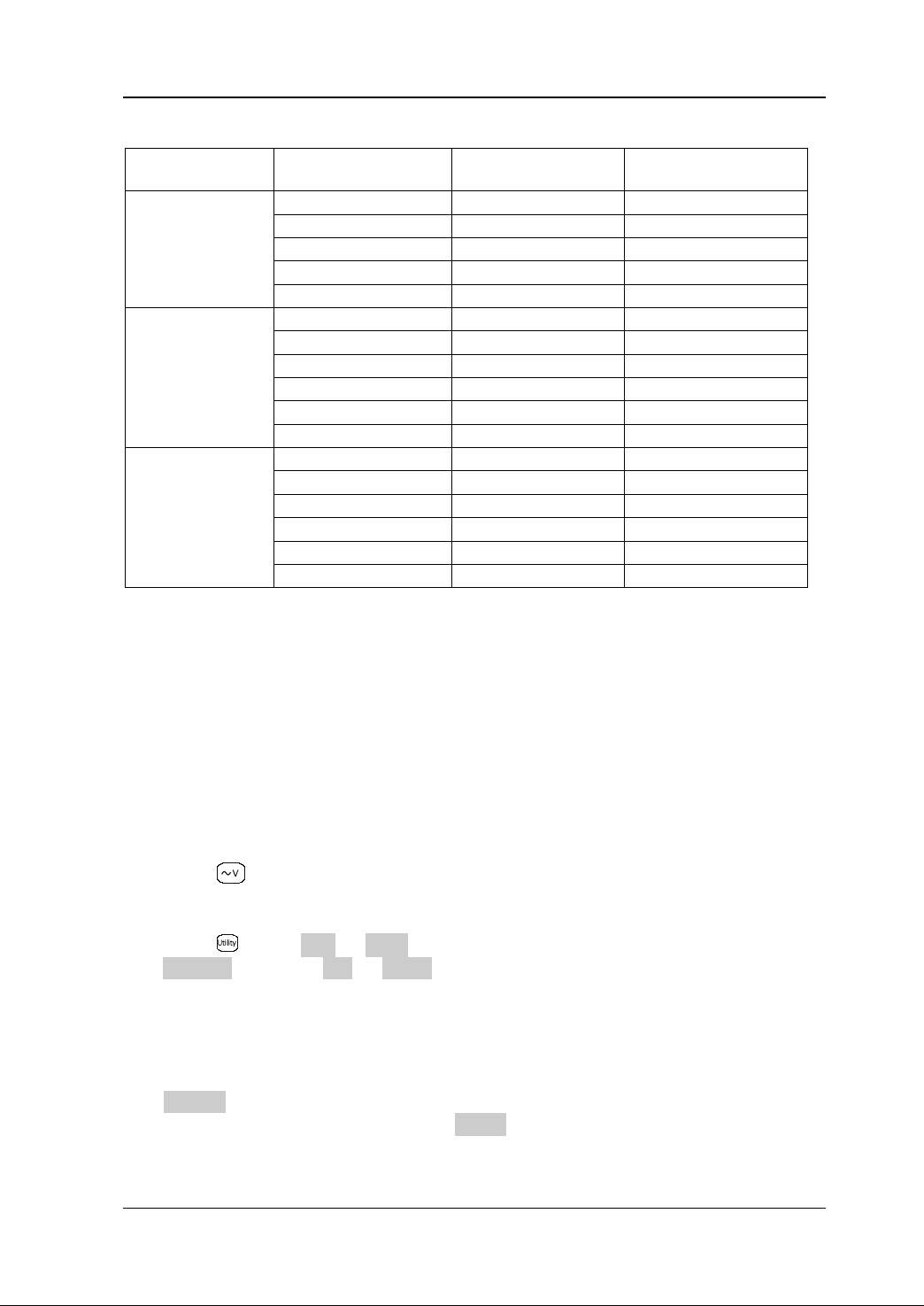
Calibration Devices
You are recommended to use the devices listed in Table 1-1 to calibrate
DM3058/DM3058E digital multimeter. If you do not have these devices, please use
other devices that can meet the "Precision Requirement" in the table below.
Table 1-1 Recommended Devices
Item Recommended Device Precision Requirement
Zero Point Calibration None Pure copper 4-terminal short-circuiter
DC Voltage Fluke 5520A
<1/5 of the 1-year parameters of the
instrument
DC Current Fluke 5520A
<1/5 of the 1-year parameters of the
instrument
Resistance Fluke 5520A
<1/5 of the 1-year parameters of the
instrument
AC Voltage Fluke 5520A
<1/5 of the 1-year parameters of the
instrument
AC Current Fluke 5520A
<1/5 of the 1-year parameters of the
instrument
Frequency Fluke 5520A
<1/5 of the 1-year parameters of the
instrument
Capacitance Fluke 5520A
<1/5 of the 1-year parameters of the
instrument
Test Conditions
For the optimum performance, all the procedures should comply with the following
recommendations.
1. Provide proper working voltage for the device.
2. Make sure the environment temperature is stable and between 18℃and 28℃.
Ideally, the calibration should be performed at 23℃±2℃.
3. Make sure the environment relative humidity is lower than 80%.
4. Make sure that the instrument has been warmed up for more than 1 hour before
the test or calibration.

Chapter 1 Calibration Overview RIGOL
DM3058/DM3058E Calibration Guide
1-3
5. Use copper connectors to reduce the effect of thermoelectric potential.
6. Use Teflon shielded twisted pair (as short as possible) to reduce the effect of
external interference. When making capacitance verification and calibration, use
coaxial cable to minimize the external interference and noise.
7. Ground the shield of the twisted pair and the shield of the coaxial cable. Unless
otherwise noted, ground the LO terminal of the calibrator.
As DM3058/DM3058E digital multimeter is a high-precision measuring instrument,
special care should be paid during the verification and calibration to avoid causing
additional error. Ideally, the accuracy of the standard source of the verification and
calibration should be more than 5 times higher than the accuracy specification of the
test instrument.
When performing the DC voltage, DC current and resistance gain calibrations, the "0"
output of the calibrator must be correct. To reduce the error caused by the connecting
cable, the connecting cable must be adequately warmed up (for about 5 minutes)
each time when the connecting cable or the short-circuiter is re-connected.
Input Connection
For the zero point calibration, please use copper or copper alloy low thermoelectric
potential 4-terminal short-circuiter. For the capacitance calibration, please use coaxial
cable and connect its shielding layer with the LO terminal. For the calibrations of the
other functions, please use Teflon shielded twisted pair (as short as possible) to
connect the multimeter and calibrator; the HI and LO terminals must be connected
with twisted pair; the HI-Sense and LO-Sense terminals must be connected with the
twisted pair. The shielding layer of the cable must be connected to the reference
ground. This kind of connection can reduce the effect of the thermoelectric potential
and external interference.


Chapter 2 Calibration RIGOL
DM3058/DM3058E Calibration Guide
2-1
Chapter 2 Calibration
Calibration Explanation
The DM3058/DM3058E calibration consists of user calibration and factory calibration.
The calibration parameters acquired from the calibration performed by RIGOL factory
or the RIGOL authorized third-party organizations are stored as the factory
calibration parameters. The calibration parameters acquired by performing the
calibration operations mentioned below are the user calibration parameters which will
not overwrite the factory calibration parameters. You can select the desired type of
calibration parameters or restore the user calibration parameters to the default values
via the menus. After the user calibration parameters are saved, they will not be lost at
power-off.
Press ; press T/C PSW and input the correct password; set SecrOff. Then,
press Cal to enter the calibration menu and execute the calibration to acquire the user
calibration parameters. You can press Default under the calibration menu to restore
the user calibration parameters to the default values. Press On/Off to select “On” and
the multimeter will correct the measurement results according to user calibration
parameters; press On/Off to select “Off” and the multimeter will use the factory
calibration parameters.
DC Voltage, DC Current and Resistance
Calibrations
The calibrations of the DC voltage, DC current and resistance measurement functions
consist of the zero point calibration and gain calibration. You should first perform the
zero point calibration and then perform the gain calibration.
The calibration procedures of the DC voltage, DC current and resistance measurement
functions are similar. The introductions below illustrate the calibration procedures by
taking the 4-wire 20 kΩ scale as an example.
1. Read the "Calibration Devices" and "Test Conditions".
2. Press to select the 4-wire resistance measurement function. Set the range to
20 kΩ and the reading rate to "Slow".
3. Press ; press T/C PSW and input the correct calibration password; set
SecrOff and press Cal Enter.
4. As shown in Figure 2-1, short-circuit the Input HI-LO terminal and Sense HI-LO
terminal (namely the zero point calibration input) using a 4-terminal

RIGOL Chapter 2 Calibration
DM3058/DM3058E Calibration Guide
2-2
short-circuiter. Press Zero to perform the zero point calibration. The zero point
calibration parameters will be displayed in the Cal 0 table after the zero point
calibration finishes.
Figure 2-1 Short-circuit of the Input HI-LO and Sense HI-LO Terminals
5. After the zero point calibration finishes, connect the Input HI-LO terminal and
Sense HI-LO terminal with the corresponding output terminals of the calibrator.
Set the output of the calibrator to 4-wire resistance 20 kΩ (namely the gain
calibration input). Turn on the output of the calibrator and wait until the output of
the calibrator becomes stable. Then, press Gain to perform the gain calibration.
The gain calibration parameters will be displayed in the Cal G table after the gain
calibration finishes.
6. After the above calibrations finish, press Save to save the calibration parameters.
Note
Special care should be paid during the calibration process to avoid affecting the
performance of the instrument. Please read the "Test Conditions" before
performing the calibration.
Chapter 2 Calibration RIGOL
DM3058/DM3058E Calibration Guide
2-3
Table 2-1 DC Voltage, DC Current and Resistance Calibration Inputs
Function Range Scale Zero Point
Calibration Input[1] Gain Calibration
Input
DC Voltage
200.000 mV
short
200.000 mV
2.00000 V
short
2.00000 V
20.0000 V
short
20.0000 V
200.000 V
short
200.000 V
1000.00 V
short
1000.00 V
DC Current
200.000 μA
open
200.000 μA
2.00000 mA
open
2.00000 mA
20.0000 mA
open
20.0000 mA
200.000 mA
open
200.000 mA
2.00000 A
open
2.00000 A
10.0000 A
open
10.0000 A
Resistance
200.000 Ω
short
200.000 Ω
2.00000 kΩ
short
2.00000 kΩ
20.0000 kΩ
short
20.0000 kΩ
200.000 kΩ
short
200.000 kΩ
2.00000 MΩ
short
2.00000 MΩ
10.0000 MΩ
short
10.0000 MΩ
Note[1]: Use the 4-terminal short-circuiter for short-circuit.
AC Voltage and AC Current Calibrations
The AC voltage and AC current calibrations consist of the half range calibration and
gain calibration. You should first perform the half range calibration and then perform
the gain calibration. The introductions below illustrate the calibration procedures by
taking the AC voltage 200 mV scale as an example.
1. Read the "Calibration Devices" and "Test Conditions".
2. Press to select the AC voltage measurement function. Set the range to the
200 mV scale and set the reading rate to "Slow".
3. Press ; press T/C PSW and input the correct calibration password; set
SecrOff and press Cal Enter.
4. Connect the voltage output terminal of the calibrator with the HI-LO input
terminal of the multimeter. Set the calibrator to output a 100 mV, 1 kHz sine
waveform (namely the half range calibration output). Turn on the output of the
calibrator and wait until the output of the calibrator becomes stable. Then, press
Middle to perform the half range calibration; the half range calibration
parameters will be displayed in the Cal M table after the half range calibration
finishes.

RIGOL Chapter 2 Calibration
DM3058/DM3058E Calibration Guide
2-4
5. After the half range calibration finishes, set the calibrator to output a 200 mV, 1
kHz sine waveform (namely the gain calibration input). Turn on the output of the
calibrator and wait until the output of the calibrator becomes stable. Then, press
Gain to perform the gain calibration; the gain calibration parameters will be
displayed in the Cal G table after the gain calibration finishes.
6. After the above calibrations finish, press Save to save the calibration parameters.
Table 2-2 AC Voltage and AC Current Calibration Inputs
Function Range Scale
Half Range
Calibration Input[1] Gain Calibration Input
AC Voltage
200 mV
1 kHz/100 mV
1 kHz/200 mV
2 V
1 kHz/1 V
1 kHz/2 V
20 V
1 kHz/10 V
1 kHz/20 V
200 V
1 kHz/100 V
1 kHz/200 V
750 V
1 kHz/375 V
1 kHz/750 V
AC Current
20 mA
1 kHz/10 mA
1 kHz/20 mA
200 mA
1 kHz/100 mA
1 kHz/200 mA
2 A
1 kHz/1 A
1 kHz/2 A
10 A
1 kHz/5 A
1 kHz/10 A
Frequency Calibration
For the frequency function, you only need to perform the gain calibration and the
operation procedures are as follows.
1. Read the "Calibration Devices" and "Test Conditions".
2. Press to select the frequency measurement function and set the range to
the manual 2 V scale.
3. Press ; press T/C PSW and input the correct calibration password; set
SecrOff and press Cal Enter.
4. Connect the voltage output terminal of the calibrator with the HI-LO input
terminal of the multimeter. Set the calibrator to output a 2 V, 100 kHz sine
waveform. Turn on the output of the calibrator and wait until the output of the
calibrator becomes stable. Then, press Gain to perform the gain calibration; the
gain calibration parameters will be displayed in the Cal G table after the gain
calibration finishes.
5. After the gain calibration finishes, press Save to save the calibration parameters.
Other manuals for DM3058
5
This manual suits for next models
1
Table of contents
Other Rigol Multimeter manuals

Rigol
Rigol DM3063 User manual

Rigol
Rigol DM3068 User manual

Rigol
Rigol DM3058 Operating instructions

Rigol
Rigol DM3068-OB User manual

Rigol
Rigol DM3058 Operating instructions

Rigol
Rigol DM3058 User manual

Rigol
Rigol DM3061 User manual

Rigol
Rigol DM3000 Series Operating instructions

Rigol
Rigol DM3068 User manual

Rigol
Rigol DM3068 Installation and operation manual


