DAYLIFF ULTRASUN UFD Installation instructions
Installation &
Operating Manual
ULTRASUN UFD
Flatplate Solar Systems


SPECIFICATIONS
1.
1
4.
SITING 5
INDEX
© Davis & Shirtliff Ltd 2020
Contents herein are not warranted
5.
INSTALLATION 6
6.
SYSTEM COMMISSIONING 7
7.
USAGE 7
8.
MAINTENANCE 7
9.
TROUBLE SHOOTING 8
10.
TERMS OF WARRANTY 10
3.
WARNINGS & SYMBOLS 3
2.
EQUIPMENT SPECIFICATIONS 3
1
1. SPECIFICATIONS
Ultrasun UFD Flatplate solar hot water systems are established and effective heaters that
provide excellent performance, good value and guaranteed long life. They are of Open
Loop thermosyphon type with the water flow circulating through the collectors and being
stored in the tank ready for use. Features include:-
• Heavy duty tank that features a resin insulated totally weather proof GRP casing, a
heavy duty galvanised cylinder internally piped to optimise hot water availability and
magnesium sacrificial anode for cathodic corrosion protection. An in-built 3kW
electric water heater with thermostat is included as standard.
• Solar collectors that incorporate full area copper absorption plates ultrasonically
welded to copper circulation tubes, high specification insulation and tempered
security glass to provide energy absorption of up to 95%.
• Low thermal conductivity high specification plastic collector tank connection piping
with silver foil coated polystyrene insulation jackets.
• Connection piping that includes an incoming non-return valve, a thermosyphon
0
diverter valve controlling max water temperature to 60 C to avoid scalding on hot
days, pressure release valve and drain cock. All fittings are provided from the inlet to
the outlet for simple installation.
• Galvanised mounting frame.
Ultrasun UFD Flatplate solar water systems are available in various tank sizes and collector
configurations to suit domestic and small scale institutional applications. They are effective
and robust products designed for many years of trouble free operation with a 5 year
guarantee to demonstrate the product quality. With the benefits of progressive design and
high quality components they are the ideal solution for all solar water heating applications.
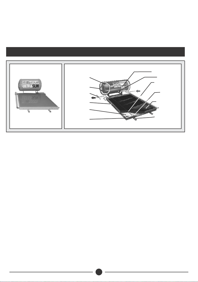
DESIGN FEATURES
Congratulations on selecting a Ultrasun UFD Flatplate Solar Hot Water
System. They are manufactured to the highest standards and if
installed and operated correctly will give many years of efcient and
trouble free service. Careful reading of this Installation Manual is
therefore important, though should there be any queries they should
be referred to the equipment supplier.
Magnesium anode bar
for corrosion protection
Elegant long life GRP resin
insulated tank casing
Copper riser pipes and
manifold tubes
High transmittance
tempered security glass
cover
Rigid galvanised rectangular
section mounting frame for
ease of installation
Screwed brass outlets
3kW electric booster
heater
High pressure galvanised
steel storage tank with internal
piping designed to optimise
hot water availability
Pure aluminium powder
coated frame
Outlet piped from hottest area
of tank with air bleed and
pressure release valve fitted
Multi layer internal
insulation including injected
polyurethane base coated
with mineral wool and covered
with aluminium foil
Full area black coated copper
absorber sheet ultrasonically
welded to the risers to
maximise heat transfer
OPERATING CONDITIONS
Water Quality: Water outside the following limits should be appropriately pre-
treated:
Direct: Clarity: Clear, TDS: <600mg/l, Hardness: <200mg/l CaCo , Saturation
3
Index: >0.8<1.0
Test Pressure: Tank - 5Bar, Collector -10Bar
Max Operating Pressure - 3.5Bar
3
Max Flow Rate - 2m /hr
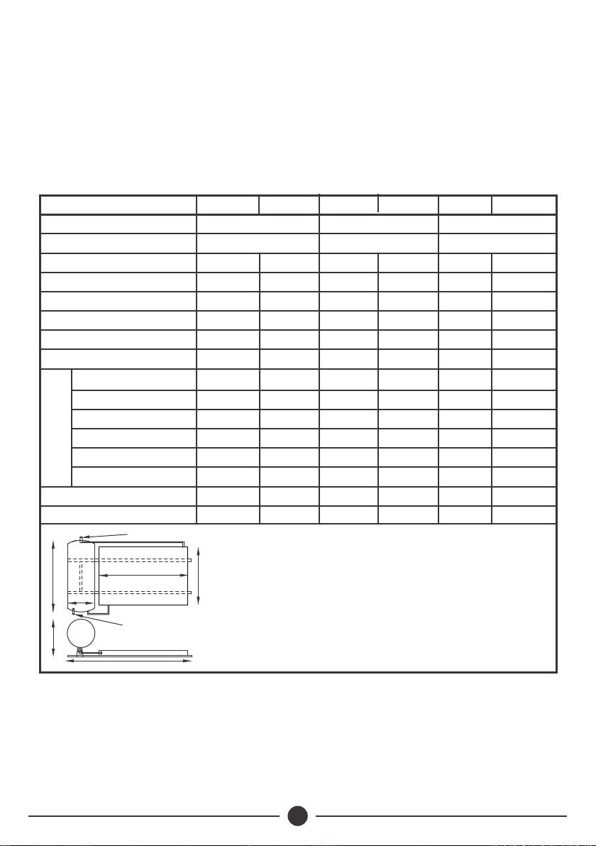
SPECIFICATIONS
Model
Typical Household (People)
Collector Model
UFD320DL
Max Heat Output/Day (kWhrs)
Collector Fluid Capacity (litres)
Min Heat Output/Day (kWhrs)
Collector Weight (kg)
3
Collector Area (m )
UFD160DS UFD220DL
5
160
1.7
1.2
9
1 X FCP1.7 2 X FCP1.7
25
6
UFD160DL
2.4
1.5
14
1 X FCP2.4 2 X FCP2.4
38
10
UFD220DS
7
220
2.4
1.5
14
38
10
3.4
2.4
20
50
14
10
320
4.8
3.0
29
76
19
System Tank Size (Litres)
1 X FCP3.01 X FCP2.4
UFD320DS
3.0
1.7
18
48
12
A
B
C
D
E
Full Weight (kg)
Empty Weight (kg)
Dimensions (mm)
F
800
1920
2620
2780
700
253
93
600
800
1890
2590
2780
700
270
110
600
800
1890
2590
2780
700
355
135
600
1760
1920
2620
2780
700
376
156
600
800
2440
3140
2780
700
490
180
600
1760
1890
2590
2780
700
534
214
600
2
A
D
C
B
Inlet 3/4” BSP
Outlet 3/4” BSP
F
E
NOTE
1. Standard output systems (S Models) should be used in hot locations and
high output systems (L Models) in more temperate ones. However hot
water availability will vary throughout the year depending on prevailing
irradiation levels and electric boosters may be necessary on cooler days.
2. Maximum heating output is based on average irradiation levels of
2
6000W/m /day prevailing in September - March and minimum Heating
2
output is based on average irradiation levels of 4000W/m /dayprevailing
in June/July and are for indicative purposes only.

33
Tanks are manufactured from galvanised steel plate and all have an in-built electric
booster heater and magnesium anode to prevent corrosion. They are encased in an
insulated fibreglass housing.
Collectors incorporate full area copper absorption plates ultrasonically welded to copper
circulation tubes which are enclosed in an insulated glass covered housing.
Heater systems are supplied complete with all piping connections including a bleed cock
and a pressure release valve at the tank outlet.
3. WARNING AND SYMBOLS
The installation of the solar system must be in accordance with
the relevant requirements of the local authority building
regulations as well as regulations for the prevention of
accidents when carrying out works such as solar installation. It
is necessary to do so in a safe and workman like manner,
taking due care of any aspects of the works that could result in
injuries to person in or about the building as well as workers,
passers by and the general public at large.
2. EQUIPMENT SPECIFICATIONS
The equipment supplied comprises of two principal components, the tank and the
collectors which are mounted together on a frame. The units work on the thermosyphon
principal whereby the temperature differential between the top and bottom of the system
creates water circulation thus facilitating the heating process. Two tank specifications are
available offering direct or indirect heating. Indirect heating uses a separate flow of pure
water through the collector which transfers heat to the service water through a jacket
around the storage tank. Indirect heating tanks are slightly less efficient though should be
used when the service water is highly mineralised. Tank layouts are shown below:-
34
These instructions describe mounting and installation of
thermosiphon solar water heaters. All installations must be
done by authorised people.
Installers must adhere to the valid work protection regulations,
in particular when working on the roof. Anti-fall protection
must be employed whenever there is a risk of falling.
To avoid the risk of being burned or scalded by hot
components, Installation and replacement of collectors or
parts should be done on cloudy days. Installation work on
sunny days should be carried out only in the morning or
evening or with the collector covered.
To avoid the risk of being burned or scalded by hot solar fluid
or components, fill and flush the solar system when the
collectors are cold. The collectors should be covered while
doing so.
Steam can escape from the expansion relief valve of the solar
pump unit if the system is shut down. To avoid injuries an
expansion relief valve must be connected to a collecting
container with a hose line
In order to ensure a seamless operation of the product, the
safety valve should be cleaned periodically and checked for
proper functions. In areas with very calcareous water the calk
residuals on the valve should frequently be cleaned off.
The product shall be installed in an area where children cannot
access.
Immersion heater is intended as standby device for water
heating and should not be used continuosly.
In areas with hard water hot water temperature should not
0
exceed 45 C to avoid calcification.
Work should be preceded by a risk assessment covering all
aspects of health and safety risks, or training requirements
that can reasonably be foreseen to be associated with the
work.

5
After the expiry of the guarantee period, if the magnesium
anode rod is worn out, the anode rod shall be replaced by a
new one in accordance with the instructions in the users’
manual.
4. SITING
Correct siting is critical for the effective operating of a solar water heater, the following
being important guidelines:-
l Orientate the principal axis of the units in a North/South direction, with the collector
facing the equator. This orientation is important to maximise sun exposure on the
collector as it tracks on its East /West axis throughout the day.
0
l Tilt at approx 15 . This is important as it optimises irradiation and also assists in the
thermosyphon process. Heater units should never be laid flat.
l Avoid any shade, especially between 10am and 4pm. Shade hugely reduces system
efficiency.
Preferably, solar panels should be installed on roofs where solar irradiation is highest and
they are also less exposed to damage. If this is not possible a protected ground sitting is
acceptable.
NORTH
EASTWEST
SOUTH
Hot Water OutCold
Water In
NORTH
EAST
WEST
SOUTH
Hot Water Out Cold
Water In
ORIENTATION OF SYSTEM
NORTH OF THE EQUATOR
ORIENTATION OF SYSTEM
SOUTH OF THE EQUATOR
This product is designed for water heating purposes using
solar energy and it may not be changed or modified in any
way. It should be installed by a qualified person, who should
observe the applicable local regulations and the building
code.
6
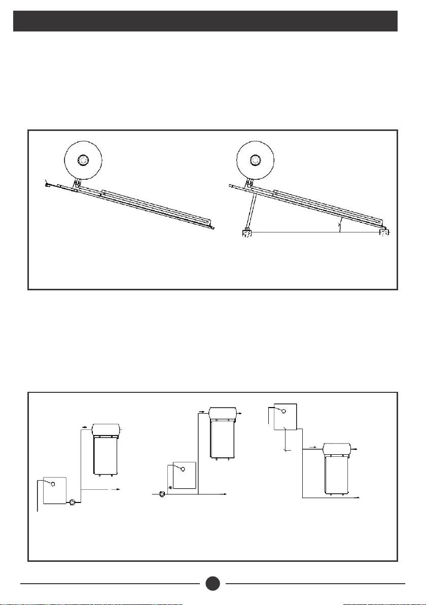
5. INSTALLATION
Ultrasun UFD solar heaters are provided with drilled frames incorporating a support cross
bar. On roofs the preferable mounting arrangement is by means of hooks affixed to the
cross bar and secured to an appropriate mounting point on the roof beams. Suspension
from the hooks is generally sufficient and fixed location is not necessary.
For ground installation rear support legs are available which should be mounted on small
concrete feet as shown below:-
ROOF INSTALLATION
TRUSS
GROUND INSTALLATION
The units can be installed using a gravity system or pressurised supply. Pressurised systems
are preferable as they give higher line pressures up to a maximum of 3.5 Bar. Note that in
the case of pressurised supply hot and cold lines must be pressurised at the same pressure
to ensure even temperature control. The systems are easy to plumb being provided with two
piping connections only, the inlet and outlet. It is important to fit a non-return valve and
isolating valve on the inlet line. Suggested installation layout arrangements are shown
below:-
Cold In
Cold
Water
Supply
Hot
Water
Supply
Cold In Hot
Water
Supply
Cold
Water
Supply
Cold
Water
Supply
Hot
Water
Supply
Cold
In
Cold In
PUMPED SUPPLY
FROM TANK
DIRECT PUMPED SUPPLY
WITH COLD WATER STANDBY
HEADER TANK
GRAVITY SUPPLY

7
All units are fitted with 3kW electric booster heaters which should be connected to the
mains supply via 20A fuse or MCB by a qualified electrician. Manual control is suggested
with the switch mounted in a convenient place.
6. SYSTEM COMMISSIONING
a) Direct Systems
On installation or after service it is important that the system is primed. This is carried
out by first opening the incoming feed followed by the bleed cock and then observing
when all air is expended from the bleed outlet. Proper priming is important or else the
unit will not operate at full efficiency
b) Indirect Systems
As well as priming the service water as indicated above, it is important to fill the
heating system with pure water. Ordinary lowly mineralised tap or drinking water is
suitable and care must be taken to completely fill the collector and tank jacket. This is
done using the priming plug on top of the tank and carefully filling the unit until all air
is expended. It is also important to open the top collector bleed plug to ensure air
pockets are eliminated in the collection capillaries. Once primed, it is vital to ensure
that the system is properly sealed as fluid loss will render the system ineffective. The
system must therefore be thoroughly checked for leaks when operating and they must
be sealed accordingly.
7. USAGE
It is important that the hot water availability is properly managed as solar energy
heating only occurs between the hours of 9:00am - 4:00pm. This effectively means
that hot water is available in the evening as any draw off will result in temperature
reduction from the replacement cold water. If hot water is required in the morning
there should either be no night time draw off or the booster heater should be used.
Users should plan hot water usage accordingly.
8. MAINTENANCE
a) Direct Systems
Direct hot water system have no moving parts and are essentially maintenance free,
though periodically the collector glass cover should be cleaned as a dust layer will
reduce efficiency.
b) Indirect Systems
Indirect systems rely on the small volume of circulated heating water in the sealed
system and full efficiency is obtained only when it is fully charged with water. The units
must therefore be regularly checked, recommended on a monthly basis and any
leaked water replaced.

8
Periodically, recommended every three months a general inspection should be made
and the following items checked:-
l Collector condition, leaking unions, dirty or broken glass, damaged water seals.
l Tank condition including casing damage, piping leaks and valve operation.
l Electric heater power connections.
l Replace worn out magnesium anode periodically.
l Booster pump and pressure tank settings (if applicable).
l Check shading of collectors
Once a year, it is recommended to flush the collectors to remove any settled
sediments that may affect the thermosyphon flow.
9. TROUBLE SHOOTING
PROBLEM POSSIBLE CAUSE SOLUTION
Insufficient
hot water
High hot water usage at night Rotation use or replace with a larger
system
Prevailing weather conditions
Incorporate complimentary electric
heater to be used when irradiation
is low
Non-operation of electric booster Replace the electric heater
Air locks in the collectors Ensure tank connections are higher
than collectors connection
Slow leaks by system or pipe work
Pressure test the pipes
Visually inspect for leaks. Raise top
right hand corner on the system
Blockage in the connection pipes
Unblock then pipes
Collectors blocked with sediments
Flush collectors with clean water to
clear the sediments
Replace the blocked pipes
Incorporate a filter in the pipework
DIRECT SYSTEMS
9
INDIRECT SYSTEMS
POSSIBLE CAUSE SOLUTION
Heated water
loss Leaking water pipes Check regularly for leaks and repair
PROBLEM
Inoperative
electric heater
Power supply or booster switch off Switch on power or booster switch
Blown fuse Replace fuse
Tripped circuit breaker Switch on the breaker
Thermostat failure Replace the thermostat
Low thermostat setting Adjust the thermostat
Faulty electric element Check element circuit continuity and
replace the element if faulty
Water discharge
from pressure
release valve
Pressure above 3 bar Lift valve hand lever and reset valve
High mains pressure Use a pressure tank to regulate and
reduce pressure levels
Pressure is below specification settings Replace the valve if discharge
continues
Pressure feedback from another device
Check that there is no feedback
pressure from another device
connected to hot reticulation
circuit
Insufficient
pressure
Inlet water strainer blocked Unblock the strainer
Unit supply pipework blocked or
undersized
Unblock the pipe work
Replace with correct pipework
Mains supply pressure below 1 bar Consult supply authority for
modifications to the system
Pressure control valve flow insufficient
for user’s requirements
Install a large valve but should not
exceed rated tank pressure of 3.5
bar

10
10. TERMS OF WARRANTY
i) General Liability
ii) Standard Warranty
• In lieu of any warranty, condition or liability implied by law, the liability of Davis &
Shirtliff (hereafter called the Company) in respect of any defect or failure of
equipment supplied is limited to making good by replacement or repair (at
the Company's discretion) defects which under proper use appear therein and
arise solely from faulty design, materials or workmanship within a specified
period. This period commences immediately after the equipment has been
delivered to the customer and at its termination all liability ceases. Also the
warranty period will be assessed on the basis of the date that the Company
is informed of the failure.
• This warranty applies solely to equipment supplied and no claim for
consequential damages, however arising, will be entertained. Also the
warranty specifically excludes defects caused by fair wear and tear, the effects of
careless handling, lack of maintenance, faulty installation, incompetence on
the part of the equipment user, Acts of God or any other cause beyond the
Company's reasonable control. Also, any repair or attempt at repair carried out
by any other party invalidates all warranties.
General Terms
If equipment failure occurs in the normal course of service having been competently
installed and when operating within its specified duty limits warranty will be
provided as follows:-
• Up to three years - The item will be replaced or repaired at no charge.
• Over three years, less than ve years - The item will be replaced or
repaired at a cost to the customer of 50% of the Davis & Shirtliff market
price.
The warranty on equipment supplied or installed by others is conditional upon the
defective unit being promptly returned free to a Davis & Shirtliff ofce and
collected thereafter when repaired. No element of site repair is included in the
warranty and any site attendance costs will be payable in full at standard chargeout
rates.


INS455A-07/20
This manual suits for next models
6
Table of contents
Other DAYLIFF Water System manuals


Popular Water System manuals by other brands


AutoAqua
AutoAqua Smart ATO Lite manual

ReadyRefresh
ReadyRefresh AccuPure FF1 instructions

Kinetico
Kinetico Drinking Water System Plus Deluxe owner's manual

Grundfos
Grundfos alpha2 l instructions

Watts
Watts WQC4 RO SERIES Installation, operation and maintenance manual

salmson
salmson Siriux Series Installation and starting instructions