Daystrom Heathkit CAPACI-TESTER CT-1 Guide

\fi reJ. Jdv33tl
By Mfc*
Assembling
and Using Your...
mm
mm
CAPACI-TESTER
MODEL CT-1
STANDARD COLOR CODE —RESISTORS AND CAPACITORS
AXIAL LEAD RESISTOR
Br*wit —InMplstW
Mack- Naa-iaiatatad
IS
1
u
lit ml lad Sigaiacaat Fipans
Wirs waaad reiistarl have '
lit digit bam
1daskle widtk
INSULATED "FIRST RING SECOND RING THIRD RING
UNINSULATED BODY COLOR END COLOR DOT COLOR
Color First Figure Second Figure Multiplier
BLACK 0-., 0None
BROWN 1 1 0
RED 22 00
ORANGE 33,000
YELLOW 4 4 •0,000
GREEN 5500,000
BLUE >66•000,000
VIOLET 770,000,000
GRAY 8-800,000,000
WHITE 99000,000,000
DISC CERAMIC RMA CODE
5-Dot 3-0*1
Capacity.,
-Temp. CmH.
RADIAL LEAD DOT RESISTOR
"tad Figare
1st Figar*
S-D0T RADIAL LEAD CERAMIC CAPACITOR
-Capacity EXTENDED RANGE TC CERAMIC HICAP
Teaip.Caaf. p^Capacity
TC Mahiplitr MaMplier Talaraace
RADIAL LEAD (IAND) RESISTOR
>Maltiplier
ladFlgara
RY-PASS COUPLING CERAMIC CAPACITOR
Capacity
ITallage
(Opt.)
AXIAL LEAD CERAMIC CAPACITOR
Tamp. Caaff. ——j,Capacity
h
Talaraace
"Teleraace 1st Figare
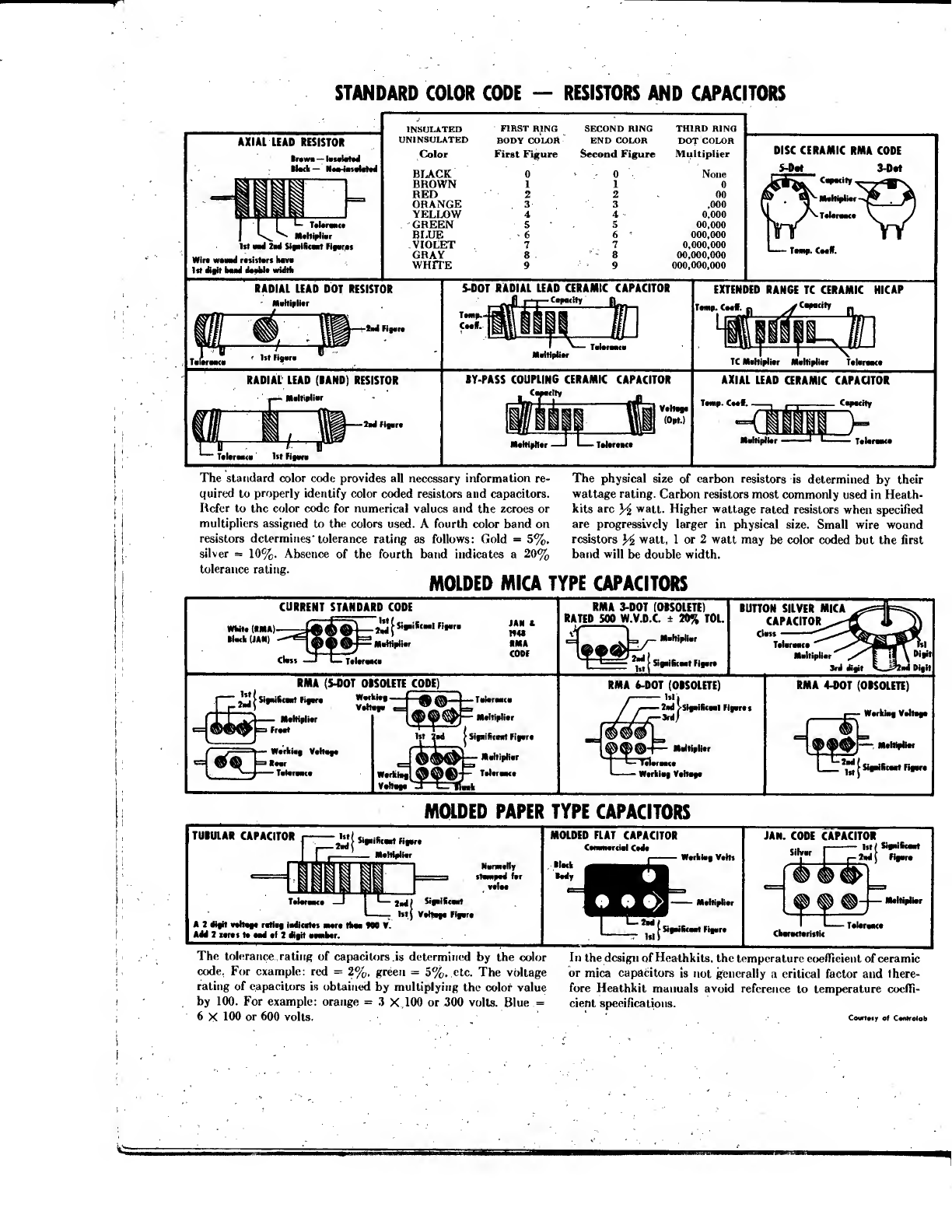
The standard color code provides all necessary information re-
quired to properly identify color coded resistors and capacitors.
Refer to the color code for numerical values and the zeroes or
multipliers assigned to the colors used. Afourth color band on
resistors determines" tolerance rating as follows: Gold =5%.
silver =10%. Absence of the fourth band indicates a20%
tolerance rating. MOLDED MICA TYPE CAPACITORS
The physical size of carbon resistors is determined by their
wattage rating. Carbon resistors most commonly used in Heath-
kits are watt. Higher wattage rated resistors when specified
are progressively larger in physical size. Small wire wound
resistors Hwatt, 1or 2watt may be color coded but the first
band will be double width.
CURRENT STANDARD CODE
,(ima)——ta, aov)—m(Ii•»it '-,''<*•'•
MIAN) '
II
Class —1L
JAN I
MM
RMA
CODI
RMA 3-D0T (0RS01ETE)
RATED 500 W.V.D.C. ±20% T0L. BUTTON SILVER MICA
CAPACITOR
Clan
Talaraaca
RMA (5-OOT 0IS0LETE CODE)
^jsiaaiac-rtFi,*,
W.rk,., Vahata
•sat
RMA 6-D0T (0IS01ETE)
-Mjufaiicaat Figeres
Signiftcasrt Fiyvrt
RMA 4-D0T (0IS0LETE)
i
—
Werklee. Verteee
MOLDED PAPER TYPE CAPACITORS
TUIULAR CAPACITOR jisigailiceat Figare
_Mahiplitr
AJdigit milage ratiaf iadicates aurt tkaa W0 V.
Add 2israt ta aad si 7digit aeaiBtr.
MOLDED FLAT CAPACITOR
Canwnarcial Caaa
Hack •
•ft •>
Warkiaa VaHs
-Mahialiar
JAN. CODE CAPACITOR
Istf Sfaifceat
-2ad( Figare
Sihrar
Take*
The tolerance rating of capacitors is determined by the color
code. For example: red =2%, green =5%, etc. The voltage
rating of capacitors is obtained by multiplying the color value
by 100. For example: orange =3X100 or 300 volts. Blue =
6X100 or 600 volts.
In the design of Healhkits, the temperature coefficient of ceramic
or mica capacitors is not generally acritical factor and there-
fore Heathkit manuals avoid reference to temperature coeffi-
cient specifications.
CovrtMy of Canlroiob
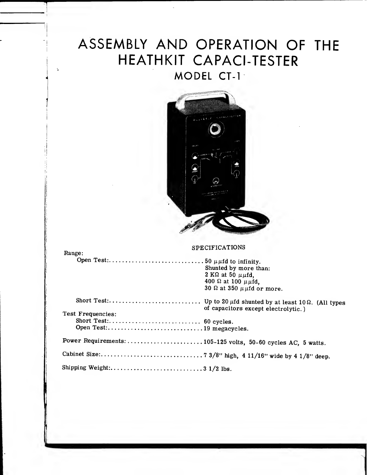
ASSEMBLY AND OPERATION OF THE
HEATHKIT CAPACI-TESTER
MODEL CT-1
SPECIFICATIONS
Range:
Open Test: 50 njufd to infinity.
Shunted by more than:
2Kft at 50 iiixid,
400 at 100 fintd,
30 at 350 jLijufd or more.
Short Test: Up to 20 /ifd shunted by at least 10 fi. (All types
of capacitors except electrolytic.
)
Test Frequencies:
Short Test: 60 cycles.
Open Test: 19 megacycles.
Power Requirements: 105-125 volts, 50-60 cycles AC, 5watts.
Cabinet Size: 73/8" high, 411/16" wide by 41/8" deep.
Shipping Weight: 31/2 lbs.

INTRODUCTION
The Heathkit model CT-1 Capacitor Tester is an instrument which will disclose open or shorted
capacitors without removing them from the circuit. It is an extremely simple instrument both
to construct and operate, but yet an instrument which should give many years of good service if
the assembly instructions are followed carefully. By not trying to "out-do" the manual to come
up with an exceptionally "pretty" wiring job, you should be able to plug it in, turn it on and veil
"Hey Ma, it works'." '
An important note should be injected here: Route wiring according to the pictorial diagrams'
Due to the high frequencies encountered within the tester, lead length and placement is quite
critical, especially around the switch.
Only one tube is used, since it can be made to "double-in-brass". It functions as an oscillator
an indicator, and it is self-rectifying. '
Afive-position switch is employed, which controls the power to the instrument, selects the test
being made (i. e. ,OPEN or SHORT), and also provides acheck on the proper operation of the
»nSrVA°^°USly:. Af?r*her exPlanation of the switch position functions will be found in the
OPERATING" section of the manual.
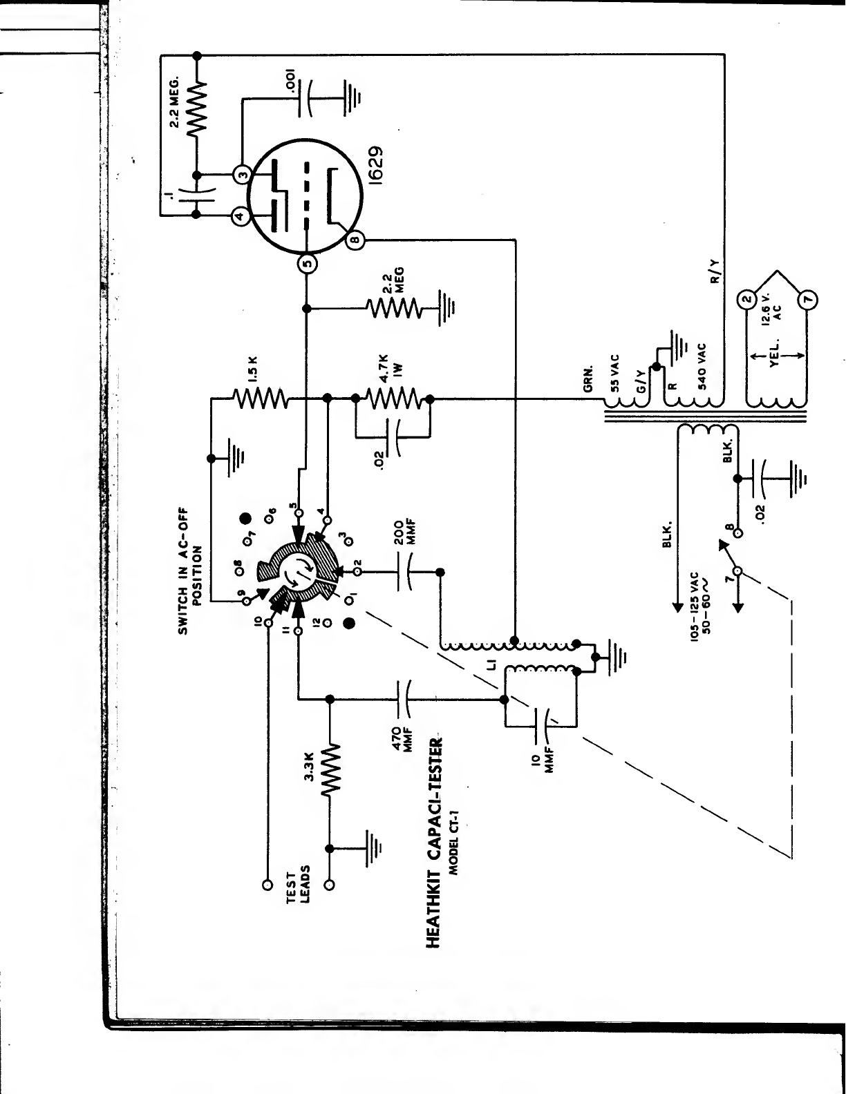
CIRCUIT DESCRIPTION
OPEN TEST: The triode section of the electron ray indicator tube, or "Magic Eye", is employed
as aconventional Hartley oscillator, but here convention ceases. Reference to the schematic
S%2 WhTIT13Secrdary"Winding COupled t0 the oscillator c^> with the oscillator
SfJtn ?""^cycles. Now here's the catch: Coupling is "tight" enough to cause the
oscillator to quit oscillating'. In this respect it can be compared to aGrid Dip Meter. As cou!
pling is increased, the absorbtive action of the coupled circuit sucks energy out of the oscillator
coil, lowering the strength of the oscillation to the point where the oscillator quits altogether
Had enough oscillators for awhile? Then let's proceed. aiiogetner.
With no oscillation present, no bias is developed across the grid leak resultine in maximum
current low through the tube Under these conditions, the eye is open to its widest angle Whe™
acapacitor which is not open (i. e. ,good or shorted) is connected across the secondary it be
comes de-tuned sufficiently to allow the circuit to oscillate. Under tSi^SSSSe Was
is developed which limits the current flow to arelatively low value, causing th? eye t^close
In other words, if the capacitor has continuity, the eye closes. Simple, eh?
SHORT TEST: Abiasing voltage, obtained from the power transformer, is fed through acur-
rent limiting network to the grid of the tube. The test leads are connected between KrW and
Eed has^oefftr^f^^r11 ^^^^V°Uage'°pening the Cowmen fs not
shorted has no effect, unless its reactance is extremely low. However areference is nrovirferf
hanGoTaTas^ff ff'T^' ^Unl6SS the ^citorU^ct^ST^
ereniefanU tt^S^i^***~ A^™io»-«- ref-
S?^ f
SUPPLY: The P°Wer SUpply in this i^trument consists of apower transformer only
No rectifier is necessary, since the "eye" tube is self-rectifying'. When the potential on the
plate is positive in respect to the cathode, current flows. When the voltage on the plate swings
negative on the other half of the cycle, no current flows, and the tube jusf"coasts" Since AC
is used on the plate and grid, proper phasing of the transformer windings is necessary
ABOUT THE MANUAL
With the exception of the circuit description, this manual was written for adefinitely non-tech-
h^\mf
ndfmdlTldUtLT°yOU with atechnical background, it may seem rather elementary to
have to follow astep-by-step procedure such as this manual incorporates. However experience
7n Ih tyP6f°flnSiructjon methods has sh°wn the method used here to be the moW foolproof
for both amateur and professional builders. The combination of pictures, diagrams and worded
Page 3

instruction is the best for the novice. It gives him an equal chance with the experienced builder,
of gaining the satisfaction of an instrument that works the first time. At the same time, the
professional constructor can benefit from the self-checking procedure, which provides the fast-
est, most convenient and "painless" way.
The written assembly instructions in this manual are divided into small operations or steps.
Each step is acomplete operation. Read the entire step through, then do that operation and
check it off as completed. After an interruption, it is easy to find where you left off by the
check marks. Read over the last checked -step and you are all ready to continue.
The major pictorials in this manual are reproduced on large separate sheets. If you fasten the
appropriate pictorial on the wall above your work space, it will save you paging back and forth
in the manual.
In the wiring (S) means solder this connection and (NS) means do not solder yet, as more wires
will be connected to this point. If more than one wire is to be soldered at aconnection point,
the instructions will appear as follows (S) (3) which means solder this connection which should
have three wires connected to it. This will provide arunning check of multiple connections.
PROPER SOLDERING PROCEDURE
Only asmall percentage of Heathkit purchasers find it necessary to return an instrument for
factory service. Of these, by far the largest proportion function improperly due to poor or
improper soldering.
Correct soldering technique is extremely important. Good solder joints are essential if the
performance engineered into the kit is to be fully realized. If you are abeginner with no ex-
perience in soldering, ahalf-hour's practice with odd lengths of wire and atube socket will be
aworthwhile investment.
High quality solder of the proper grade is most important. There are several different brands
of solder on the market, each clearly marked "Rosin. Core Radio Solder. "Such solders consist
of an alloy of tin and lead, usually in the proportion of 50:50. Minor variations exist in the mix-
ture such as 40:60, 45:55, etc. with the first figure indicating the tin content. Radio solders are
formed with one or more tubular holes through the center. These holes are filled with a rosin
compound which acts as a flux or cleaning agent during the soldering operation.
NO SEPARATE FLUX OR PASTE OF ANY KIND SHOULD BE USED. We specifically caution
against the use of so-called "non-corrosive" pastes. Such compounds, although not corrosive
at room temperatures, will form residues when heated. The residue is deposited on surround-
ing surfaces and attracts moisture. The resulting compound is not only corrosive but actually
destroys the insulation value of non- conductors. Dust and dirt will tend to accumulate on these
"bridges" and eventually will create erratic or degraded performance of the instrument.
NOTE: ALL GUARANTEES ARE VOIDED AND WE WILL NOT REPAIR OR SERVICE
INSTRUMENTS IN WHICH ACID CORE SOLDER OR PASTE FLUXES HAVE BEEN
USED. WHEN IN DOUBT ABOUT SOLDER, IT IS RECOMMENDED THAT ANEW
ROLL PLAINLY MARKED "ROSIN CORE RADIO SOLDER" BE PURCHASED.
If terminals are bright and clean and wires free of wax, frayed insulation and other foreign sub-
stances, no difficulty will be experienced in soldering. Crimp or otherwise secure the wire (or
wires) to the terminal, so agood joint is made without relying on solder for physical strength.
To make agood solder joint, the clean tip of the soldering iron should be placed against the joint
to be soldered so that the terminal is heated sufficiently to melt solder. The solder is then
placed against both the terminal and the tip of the iron and will immediately flow out over the
joint. Refer to the sketch below. Use only enough solder to cover wires at the junction; it is
Page 4
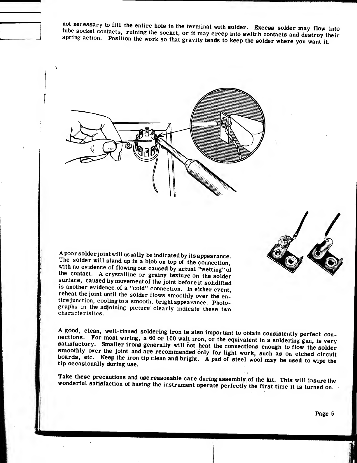
not necessary to fill the entire hole in the terminal with solder. Excess solder may flow into
snrin^M nC°n oCtS
;
rU£lng the 8°Cket'wtt »»* Cree?into switch conta^« »nd destroy their
spring action. Position the work so that gravity tends to keep the solder where you want it
Apoor solder joint will usually be indicated by its appearance
The solder will stand up in ablob on top of the connection,
with no evidence of flowing out caused by actual "wetting" of
the contact. Acrystalline or grainy texture on the solder
surface, caused by movement of the joint before it solidified
is another evidence of a"cold" connection. In either event
reheat the joint until the solder flows smoothly over the en-
tire junction, cooling to asmooth, bright appearance. Photo-
graphs in the adjoining picture clearly indicate these two
characteristics.
Agood, clean, well-tinned soldering iron is also important to obtain consistently perfect con-
nections For most wiring, a60 or 100 watt iron, or the equivalent in asoldering gun, is very
satisfactory. Smaller irons generally will not heat the connections enough to flow the solder
smoothly over the joint and are recommended only for light work, such as on etched circuit
Up Sccaslonally6Z£use" ^"* ^*^^^to U8ed t0 wi<* the
wnnL^e«L
re
«,f
aU!|0n8 f1? U8ereasonable care during assembly of the kit. This will insure the
wonderful satisfaction of having the instrument operate perfectly the first time it is turned on.
Page 5
Page 6
STEP-BY-STEP ASSEMBLY INSTRUCTIONS
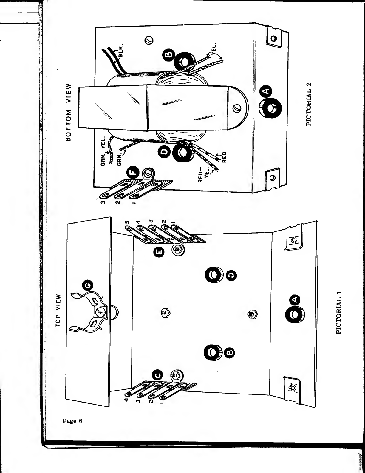
(t'T Familiarize yourself with the chassis by comparing it
to Pictorial 1. Install the 3/8" rubber grommets at lo-
cations A, Band D.
(Vf^Mount the power transformer as shown in Pictorial 2.
Use 6-32 screws, lockwashers and nuts. Don't forget
to position it properly! The black and the yellow leads
are oriented near grommet B.
((^-Install afour -lug terminal strip at C, positioning as
shown in Pictorial 1. Use 6-32 screw, lockwasher and
nut.
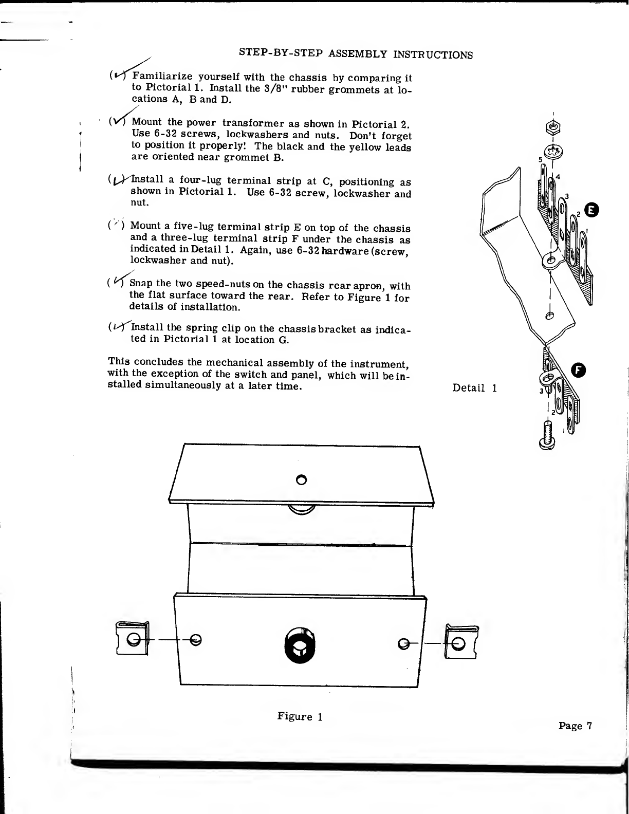
()Mount afive- lug terminal strip Eon top of the chassis
and athree-lug terminal strip Funder the chassis as
indicated in Detail 1. Again, use 6-32 hardware (screw,
lockwasher and nut).
(^Tsnap the two speed-nuts on the chassis rear apron, with
the flat surface toward the rear. Refer to Figure 1for
details of installation.
(HfInstall the spring clip on the chassis bracket as indica-
ted in Pictorial 1at location G.
This concludes the mechanical assembly of the instrument,
with the exception of the switch and panel, which will be in-
stalled simultaneously at alater time. Detail 1
Figure 1

Now would be agood time to plug in the soldering iron and take abreather and check yourself
over for any cuts, bruises and so forth which may have accumulated in the preceeding steps.
All set? Now let's go'.
(I^Push the two black and two yellow leads from the transformer up through grommet B. Cut
one of the black leads to alength sufficient to reach C4. Strip and tin the lead and connect
to C4 (NS). Refer to Pictorial 3.
{isfIn asimilar manner, prepare the other black lead and connect it to C3 (NS). Again, refer
to Pictorial 3for clarification.
(isf Dress the two yellow leads across the chassis and connect one of them to E2 (NS). Picto-
rial 3shows where.
(/'T'Likewise, connect the remaining yellow lead to E4 (NS).
Turning the chassis over, we see four leads from the transformer still swinging in the breeze.
These wires are color-coded and satisfactory operation of the "SHORT-TEST"is dependent upon
correct polarity of the transformer windings.
(t^Push the red- yellow wire up through grommet D. Cut this wire to alength sufficient to
reach El. Now strip and tin the wire and connect it to El (NS). See Pictorials 3and 4, if
you like.
(A^-Dress the plain red wire down close to the chassis as shown in Pictorial 4and connect to
F2 (NS).
{Uf Dress the green-yellow wire down to the chassis, over to the terminal strip and connect to
F2 (NS).
(^^Run the green wire over to F3 and connect (NS).
(u-^-Take a three inch long piece of hookup wire, strip the insulation back about 3/8" on both
ends and connect one end to Fl (NS). Push the other end up through grommet D. Looks
kind of silly, sticking up there all by itself, doesn't it? Don't worry, it will go to the switch
eventually.
(J-'T'Pick out a1500 fi (or 1.5 K, if you prefer) resistor (brown-green- red). Connect between
F2 (S) (3) and Fl (NS). See Pictorial 4. Press the resistor body close to the terminal strip.
(/-^-Connect a4700 J2 (4.7 K) 1-watt resistor (the big one: yellow-violet-red) between Fl (NS)
and F3 (NS). Again, refer to Pictorial 4and position directly above the terminal strip.
(^Install a.02 jnfd tubular condenser between lugs Fl (S) (4) and F3 (S) (3).
This completes the wiring under the chassis. This particular portion of the circuit is the limit-
ing network which supplies the 60-cycle voltage for the "SHORT-TEST". (See the Circuit De-
scription Section of the manual.
)
Shake out any bits of wire and solder, examine for good solder connections and take care of any
burned fingers. Ready? We're off.
Page 9

(TCut the 8- wire cable to alength of 81/2". Strip the outer covering back about 11/2" from
one end and about 21/4" from the other end. See Figure 2if you're puzzled. DON'T DAM-
AGE THE INNER WIRES'.
USE THIS END FOR USE THIS END FOR
YEL
RED-
WHT.2'
MTG. TO SOCKET „1"MTG. TO TERM. STRIP
tI- ORANGE 3
/a
c3"
a
18- WIRE CABLE
GRN. V4-»"
Figure 2r—^
lBLACK
BLUE "l _.
BROWN
Now grasp the black lead in one hand, and the rest of the cable in the other and pull. Sim-
ple, wasn't it?
^^Simils
up, ~
imilarly, remove the brown and blue wires. These may take some tugging, but don't give
up. They'll come out eventually.
(V) Cut and strip the wires to the lengths indicated in Figure 2. For ease of installation, these
wires should be tinned. Be sure all the strands of wire are twisted together. Astray strand
can cause aminor catastrophy if it happens to touch the wrong place.
Now we wire the tube socket to the cable.
(I^Bend all the socket lugs outward, as indica-
ted in Detail 2.
The socket lugs are numbered clockwise,
starting at the keyway, as shown. Connect
a2.2 megohm resistor (red- red-green) be-
tween lug 5(NS) and lug 6(NS). Position as
shown.
(l/) Assuming the loose end of the cable was pre-
pared according to apreceeding step, con-
nect the orange lead to lug 6of the socket
(S) (2). See Figure 2and Detail 2.
^Connect the green wire to lug 7(S) (1).
(rfi Run the yellow wire over the back of the
socket to lug 2and solder in place (1).
(Vf^The red wire is next connected to lug 3(S)
(1).
Now connect the white wire to lug 4(S) (1).
Lay the cable and socket assembly and the othei
wires aside for the present.
WHITE
RED 2MEGOHM
ORANGE
Detail 2
Page 10
Connect a2.2 megohm resistor (red-red- green) between El (NS) andE5 (NS). Use sleeving
as shown in Pictorial 3. Push the body of the resistor down close to the terminal strip.
{/) Connect a.1 jxfd condenser between El (NS) and E5 (NS). Place as indicated in Pictorial 3.
It is this resistor-capacitor circuit which determines the maximum angle the eye can open.
(K Connect a.001 jufd condenser from E5 (NS) to E3 (NS) (use sleeving).
Next the cable is wired to the terminal strip.
(Secure the orange lead to E3 (S) (2).
(I/) In asimilar fashion, connect the green lead to E2 (S) (2).
(W Likewise, the yellow lead goes to E4 (S) (2).
(14 Connect the white lead to El (S) (4).
(l^The red lead now goes to E5 (S) (4).
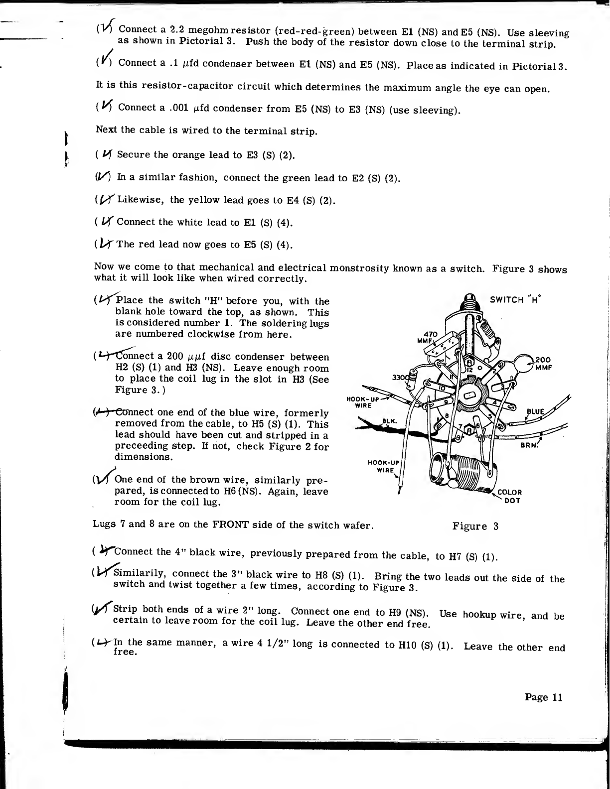
Now we come to that mechanical and electrical monstrosity known as aswitch. Figure 3shows
what it will look like when wired correctly.
(f-^Place the switch "H" before you, with the
blank hole toward the top, as shown. This
is considered number 1. The soldering lugs
are numbered clockwise from here.
(H^Connect a200 \x\ii disc condenser between
H2 (S) (1) and H3 (NS). Leave enough room
to place the coil lug in the slot in H3 (See
Figure 3.
)
(«H Connect one end of the blue wire, formerly
removed from the cable, to H5 (S) (1). This
lead should have been cut and stripped in a
preceeding step. If not, check Figure 2for
dimensions.
SWITCH V
.200
MMF
(V^One end of the brown wire, similarly pre-
pared, is connected to H6(NS). Again, leave
room for the coil lug.
Lugs 7and 8are on the FRONT side of the switch wafer.
DOT
Figure 3
(AfConnect the 4" black wire, previously prepared from the cable, to H7 (S) (1).
(l^Similarily connect the 3" black wire to H8 (S) (1). Bring the two leads out the side of the
switch and twist together afew times, according to Figure 3.
g/fStrip both ends of awire 2" long. Connect one end to H9 (NS). Use hookup wire and be
certain to leave room for the coil lug. Leave the other end free. '
(^freehe SamG man°er'awire 41/2"long is connected to H10 (S) (1). Leave the other end
Page 11
(/-Connect a3300 S2 (3.3 K) resistor (orange-orange -red) between H9 (NS) and Hll (NS). Re-
member, the coil lug goes to H9.
{hfTT^lO ji/if condenser is connected between Hll (S) (2) and H12 (NS). This lug (H12) also
receives acoil lug.
This completes the switch wiring, except for mounting the coil. This is done in the following
manner:
(UfPlace the coil against the switch with the colored dot as shown in Figure 3. Twist the lugs
of the coil slightly, so they penetrate the slots in the switch lugs H3, H6, H9andHl2. Twist
only the tip of the coil lug, back about 1/4".
(^Is the color dot oriented in the right place? Good*. Now solder H3 (2), H6 (2), H9 (3) and
H12 (2).
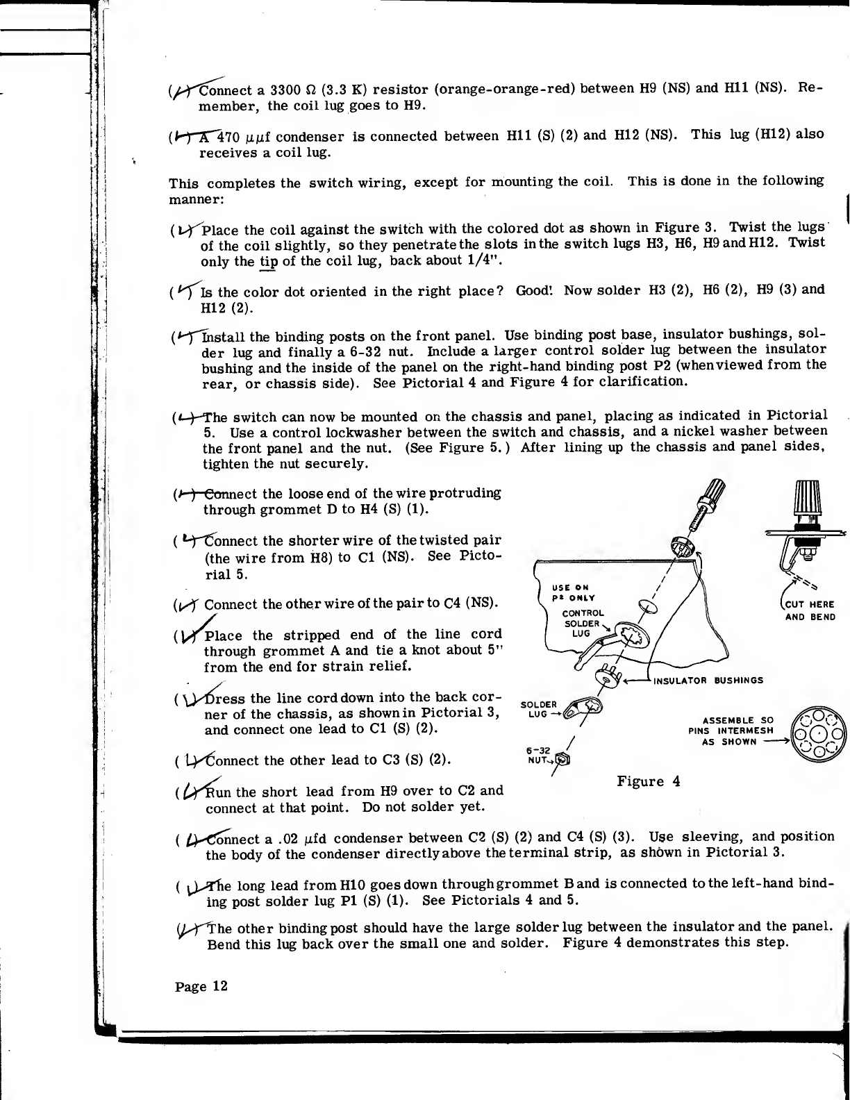
(^-flnstall the binding posts on the front panel. Use binding post base, insulator bushings, sol-
der lug and finally a6-32 nut. Include alarger control solder lug between the insulator
bushing and the inside of the panel on the right-hand binding post P2 (when viewed from the
rear, or chassis side). See Pictorial 4and Figure 4for clarification.
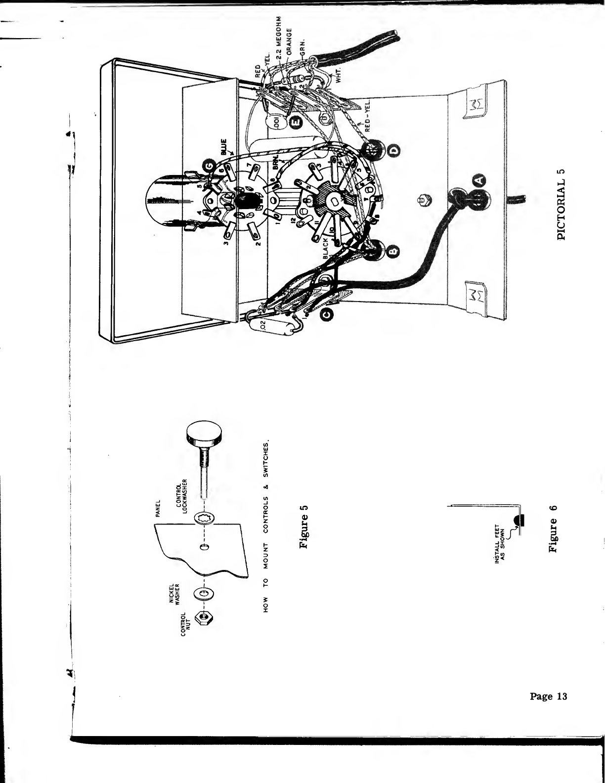
(*-)-The switch can now be mounted on the chassis and panel, placing as indicated in Pictorial
5. Use acontrol lockwasher between the switch and chassis, and anickel washer between
the front panel and the nut. (See Figure 5. )After lining up the chassis and panel sides,
tighten the nut securely.
(h)Connect the loose end of the wire protruding
through grommet Dto H4 (S) (1).
(t-ftfonnect the shorter wire of the twisted pair
(the wire from H8) to Cl (NS). See Picto-
rial 5.
(tSf Connect the other wire of the pair to C4 (NS).
(l^Vlace the stripped end of the line cord
through grommet Aand tie aknot about 5"
from the end for strain relief.
(\yf>ress the line cord down into the back cor-
ner of the chassis, as shown in Pictorial 3,
and connect one lead to Cl (S) (2).
(t^Connect the other lead to C3 (S) (2).
(£^Run the short lead from H9 over to C2 and
connect at that point. Do not solder yet.
6-32
NUT-* /
INSULATOR BUSHINGS
ASSEMBLE SO
PINS INTERMESH
AS SHOWN
Figure 4
(^Connect a.02 iiid condenser between C2 (S) (2) and C4 (S) (3). Use sleeving, and position
the body of the condenser directly above the terminal strip, as shown in Pictorial 3.
(^J^The long lead fromHIO goes down through grommet Band is connected to the left-hand bind-
ing post solder lug PI (S) (1). See Pictorials 4and 5.
(L^The other binding post should have the large solder lug between the insulator and the panel.
Bend this lug back over the small one and solder. Figure 4demonstrates this step.
Page 12
We're almost finished now.
Place the socket on the tube, being careful not to exert too much pressure in one spot. The tube will go in
quite hard the first couple of times, so don't give up yet. BE SURE THE SOCKET IS ON THE TUBE PINS
AS FAR AS IT WILL GO'. Unless the socket and tube base are in contact, an embarassing situation may
exist, where the pins will touch the metal cabinet when the unit is assembled, resulting in alittle hair-
pulling
(n/no
Now bend socket lugs 4and 5on over toward the front side of the socket. See Pictorial 5. This elim-
inates any possibility of the lugs touching the cabinet when assembled.
Snap the tube in its clip and push forward until the top bubble protrudes through the front panel. The
keyway should be pointing down. The tube envelope will not go through the hole, so stop pushing when
it won't go any farther forward.
(L-MJTess the blue lead from the switch lug 5as shown in Pictorial 5and connect to the tube socket lug 5
(S) (2).
(^TETa similar manner, the brown lead is connected to lug 8(S) (1).
Now we're on the home stretch. Next the cabinet is prepared.
(''^Install the rubber feet in the four holes on the cabinet bottom, as shown in Figure 6on Page 13.
Moistening the feet with water will facilitate insertion.
p^The handle is assembled to the cabinet top with #10 screws.
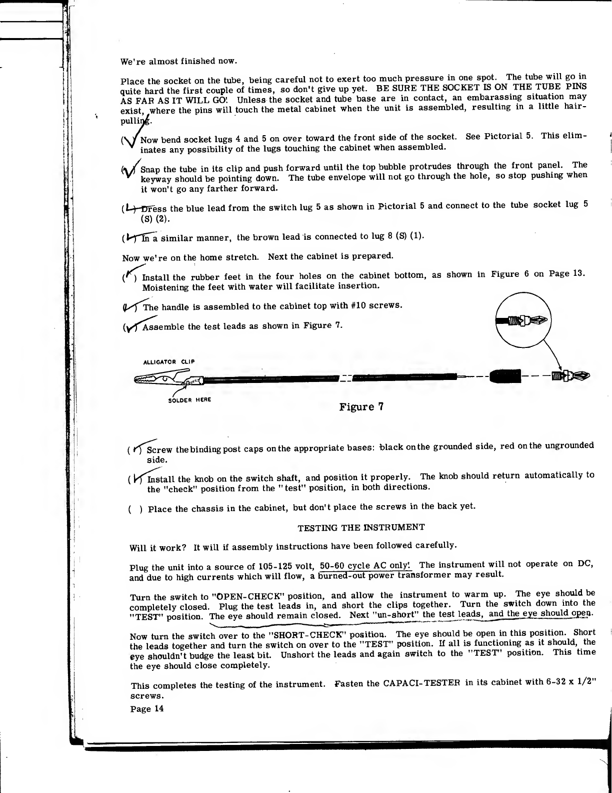
(yf*Assemble the test leads as shown in Figure 7.
ALLIGATOR CLIP
SOLDER HERE Figure 7
(ffscrew the binding post caps on the appropriate bases: black on the grounded side, red on the ungrounded
side.
(kfinstall the knob on the switch shaft, and position it properly. The knob should return automatically to
the "check" position from the "test" position, in both directions.
()Place the chassis in the cabinet, but don't place the screws in the back yet.
TESTING THE INSTRUMENT
Will it work? It will if assembly instructions have been followed carefully.
Plug the unit into asource of 105-125 volt, 50-60 cycle AC only'. The instrument will not operate on DC,
and due to high currents which will flow, aburned-out power transformer may result.
Turn the switch to "OPEN- CHECK" position, and allow the instrument to warm up. The eye should be
completely closed. Plug the test leads in, and short the clips together. Turn the switch down into the
"TEST" position. The eye should remain closed. Next "un-short" the test leads^jind the eye should open
.
Now turn the switch over to the "SHORT-CHECK" position. The eye should be open in this position. Short
the leads together and turn the switch on over to the "TEST" position. If all is functioning as it should, the
eye shouldn't budge the least bit. Unshort the leads and again switch to the "TEST" position. This time
the eye should close completely.
This completes the testing of the instrument. Fasten the CAPACI- TESTER in its cabinet with 6-32 x1/2"
screws.
Page 14
IN CASE OF DIFFICULTY
If, after careful construction proceedures have been followed, the instrument fails to operate as
indicated, check the following:
1. Check wiring carefully, step-by-step. If possible have afriend assist you in this as an
error can be consistantly overlooked.
2. Inspect for signs of definite malfunction, such as heater not lit, resistors charred or dis-
colored, overheated transformer, etc.
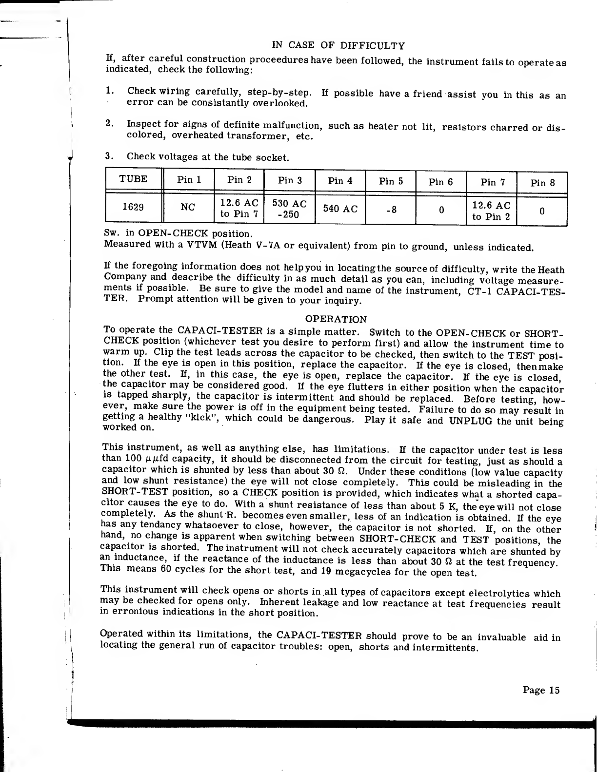
3. Check voltages at the tube socket.
TUBE Pin 1Pin 2Pin 3Pin 4Pin 5Pin 6Pin 7Pin 8
1629 NC 12.6 AC
to Pin 7
530 AC
-250 540 AC -8 012.6 AC
to Pin 20
Sw. in OPEN-CHECK position.
Measured with aVTVM (Heath V-7A or equivalent) from pin to ground, unless indicated.
If the foregoing information does not help you in locating the source of difficulty, write the Heath
Company and describe the difficulty in as much detail as you can, including voltage measure-
ments if possible. Be sure to give the model and name of the instrument, CT-1 CAPACI-TES-
TER. Prompt attention will be given to your inquiry.
OPERATION
To operate the CAPACI-TESTER is asimple matter. Switch to the OPEN-CHECK or SHORT-
CHECK position (whichever test you desire to perform first) and allow the instrument time to
warm up. Clip the test leads across the capacitor to be checked, then switch to the TEST posi-
tion. If the eye is open in this position, replace the capacitor. If the eye is closed, then make
the other test. If, in this case, the eye is open, replace the capacitor. If the eye is closed
the capacitor may be considered good. If the eye flutters in either position when the capacitor
is tapped sharply, the capacitor is intermittent and should be replaced. Before testing how-
ever, make sure the power is off in the equipment being tested. Failure to do so may result in
getting ahealthy "kick", which could be dangerous. Play it safe and UNPLUG the unit being
worked on. b
This instrument, as well as anything else, has limitations. If the capacitor under test is less
than 100 ji^fd capacity, it should be disconnected from the circuit for testing, just as should a
capacitor which is shunted by less than about 30 fi. Under these conditions (low value capacity
and low shunt resistance) the eye will not close completely. This could be misleading in the
SHORT-TEST position, so aCHECK position is provided, which indicates what ashorted capa-
citor causes the eye to do. With ashunt resistance of less than about 5K, theeyewill not close
completely. As the shunt R. becomes even smaller, less of an indication is obtained. If the eye
has any tendancy whatsoever to close, however, the capacitor is not shorted. If on the other
hand, no change is apparent when switching between SHORT- CHECK and TEST positions the
capacitor is shorted. The instrument will not check accurately capacitors which are shunted by
an inductance, if the reactance of the inductance is less than about 30 nat the test frequency
This means 60 cycles for the short test, and 19 megacycles for the open test.
This instrument will check opens or shorts in all types of capacitors except electrolytics which
may be checked for opens only. Inherent leakage and low reactance at test frequencies result
in erronious indications in the short position.
Operated within its limitations, the CAPACI-TESTER should prove to be an invaluable aid in
locating the general run of capacitor troubles: open, shorts and intermittents.
Page 15

BIBLIOGRAPHY
For those of you who are interested in finding out more about in- circuit capacitor testers, as
well as the principles utilized in the CT-1, here are some articles which should help you.
RADIO AMATEUR'S HANDBOOK, 29th Edition. American Radio Relay League. Page. 40.
RADIO ENGINEERING HANDBOOK, 1st Edition. McGraw-Hill. Page 154.
And some magazine articles:
RADIO-ELECTRONICS, June 1955, Page 72.
RADIO-ELECTRONICS, September 1955, Page 44.
RADIO AND TV NEWS, September 1955, Page 118.
REPLACEMENTS
Material supplied with Heathkits has been carefully selected to meet design requirements and
ordinarily will fulfill its function without difficulty. Occasionally improper instrument opera-
tion can be traced to afaulty tube or component. Should inspection reveal the necessity for re-
placement, write to the Heath Company and supply all of the following information:
A. Thoroughly identify the part in question by using the part number and description found in
the manual parts list.
B. Identify the type and model number of kit in which it is used.
C. Mention the order number and date of purchase.
D. Describe the nature of defect or reason for requesting replacement.
The Heath Company will promptly supply the necessary replacement. Please do not return the
original component until specifically requested to do so. Do not dismantle the component in
question as this will void the guarantee. If tubes are to be returned, pack them carefully to
prevent breakage in shipment as broken tubes are not eligible for replacement. This replace-
ment policy does not cover the free replacement of parts that may have been broken or damaged
through carelessness on the part of the kit builder.
SERVICE
If after applying the information contained in this manual and your best efforts on the unit, you
are still unable to obtain proper performance from the Instrument, it is suggested that you take
advantaged the Heath Company makes available to its customers.
The Technical Consultation Department is maintained for the purpose of Providing 1Heath cus-
tomers with apersonalized technical consultation service; this service is availab eto you with-
ouTcharge. The technical consultants are thoroughly familiar with all details of the lament
and can usually localize the trouble from asuitable description of the difficulty encountered It
is of course necessary that you provide full and complete information concerning your prob-
lem whenwriting to the Technical Consultation Department for assistance. For instance clearly
Sythe kit Involved, giving the purchase date and, if possible the invoice number; deserve
in detail the difficulty that you have encountered; state what you have attempted to do orectify
he trouble, what results have been achieved, and include any information or clues that you feel
could possibly be of value to the consultant who handles your problem. Failure to provide com-
plete descriptive details may lead to incorrect assumptions on the Part ?JhenC
^
less delay in the solution to your problem. Quite frequently, when the information given the
consultant is complete, concise and reliable, adiagnosis of the difficulty can be made wit icon-
fidence and specific instructions given for its correction. If replacement of acomponent is
invoked in the correction, the component will be shipped to you, subject to the terms and con-
ditions of the Warranty.
Page 16

The Factory Service facilities are also available to you, in case you are not familiar enough with
electronics to provide our consultants with sufficient information on which to base adiagnosis of
your difficulty, or in the event that you prefer to have the difficulty corrected in this manner.
You may return the complete Instrument to the Heath Company for inspection and necessary re-
pairs and adjustments. You will be charged afixed fee of $3.00, plus the price of any additional
parts or material required. However, if the Instrument is returned within the Warranty period,
parts charges will be governed by the terms of the Warranty. State the date of purchase and give
invoice number, if possible.
Local Service by Authorized Heathkit Dealers is also available and often will be your fastest, most
efficient method of obtaining service for your Heathkits. Although you mayfind charges for local
service somewhat higher than those listed in Heathkit manuals (for factory service), the amount
of increase is usually offset by the transportation charges you would pay if you elected to return
your kit to the Heath Company.
Heathkit dealers will honor the regular 90 day Heathkit Parts Warranty on all kits, whether pur-
chased through adealer or directly from Heath Company. It will be necessary that you verify
the purchase date of your kit by presenting your copy of the Heath Company invoice to the author-
ized dealer involved.
Under the conditions specified in the Warranty, replacement parts are supplied without charge;
however, if your local dealer assists you in locating adefective part (or parts) in your Heath-
kit, or installs areplacement part for you, he may charge you for this service.
Heathkits purchased locally and returned to Heath Company for service must be accompanied by
your copy of the dated sales receipt from your authorized Heathkit dealer in order to be eligible
for parts replacement under the terms of the Warranty.
THESE SERVICE POLICIES APPLY ONLY TO COMPLETED INSTRUMENTS CONSTRUCTED
IN ACCORDANCE WITH THE INSTRUCTIONS AS STATED IN THE MANUAL. Instruments
that are not entirely completed or instruments that are modified in design will not be accepted
for repair. Instruments showing evidence of acid core solder or paste fluxes will be returned
NOT repaired.
For information regarding modifications of Heathkits for special applications, it is suggested
that you refer to any one or more of the many publications that are available on all phases of
electronics. They can be obtained at or through your local library,, as well as at most electronic
outlet stores. Although the Heath Companywelcomes all comments and suggestions, it would be
impossible to design, test, evaluate and assume responsibility for proposed circuit changes for
specific purposes. Therefore, such modifications must be made at the discretion of the kit build-
er, according to information which will be much more readily available from some local source.
SHIPPING INSTRUCTIONS
Before returning aunit for service, be sure that all parts are securely mounted.
ATTACH ATAG TO THE INSTRUMENT GIVING
NAME, ADDRESS AND TROUBLE EXPERIENCED.
Pack in arugged container, preferably wood, using at least three inches of shredded newspaper
or excelsior on all sides. Ship the complete kit including test leads, tube, cabinet, etc. ,to
enable the service department to do acomplete job. DO NOT SHIP IN THE ORIGINAL KIT CAR-
TONAS THIS CARTON IS NOT CONSIDERED ADEQUATE FOR SAFE SHIPMENT OF THE COM-
PLATED INSTRUMENT. Ship by prepaid express if possible. Return shipment will be made by
express collect. Note that acarrier cannot be held liable for damage in transit if packing, in
HIS OPINION, is insufficient.
Page 17
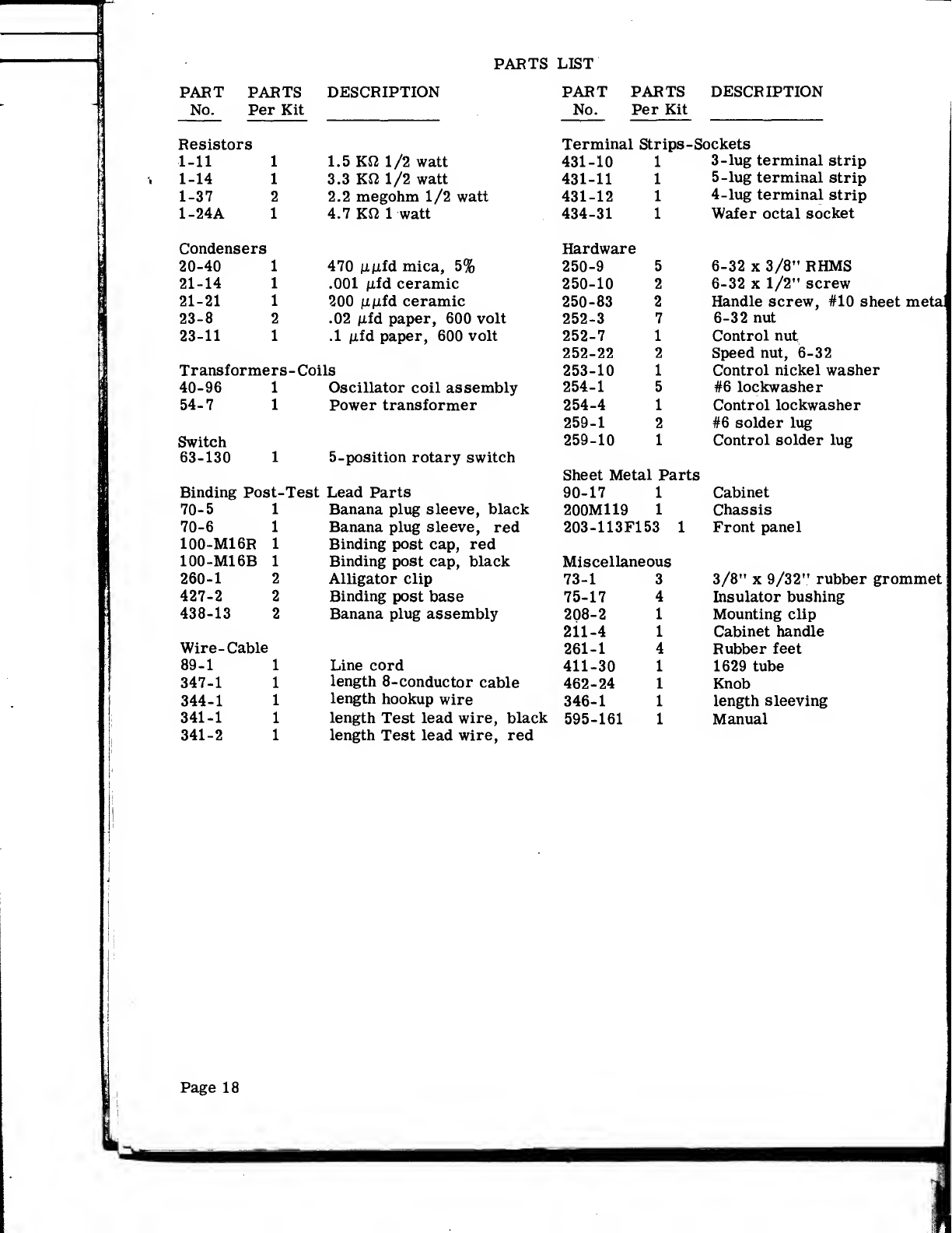
PARTS LIST
PART PARTS DESCRIPTION PART PARTS DESCRIPTION
No. Per Kit No. Per Kit
Resistors Terminal Strips -Sockets
1-11 11.5 Kft 1/2 watt 431-10 13-lug terminal strip
1-14 13.3 KS2 1/2 watt 431-11 15-lug terminal strip
1-37 22.2 megohm 1/2 watt 431-12 14-lug terminal strip
1-24A 14.7 Kfi 1watt 434-31 1Wafer octal socket
Condensers Hardware
20-40 1470 /i/ifd mica, 5% 250-9 56-32 x3/8" RHMS
21-14 1.001 fifd ceramic 250-10 26-32 x1/2" screw
21-21 1200 /i/ifd ceramic 250-83 2Handle screw, #10 sheet meta
23-8 2.02 fifd paper, 600 volt 252-3 76-32 nut
23-11 1.1 /jid paper, 600 volt 252-7 1Control nut
252-22 2Speed nut, 6-32
Transformers- Coils 253-10 1Control nickel washer
40-96 1Oscillator coil assembly 254-1 5#6 lockwasher
54-7 1Power transformer 254-4 1Control lockwasher
259-1 2#6 solder lug
Switch 259-10 1Control solder lug
63-130 15- position rotary switch Sheet Metal Parts
Binding Post-Test Lead Parts 90-17 1Cabinet
70-5 1Banana plug sleeve, black 200M119 1Chassis
70-6 1Banana plug sleeve, red 203-113F153 1Front panel
100-M16R 1Binding post cap, red
100-M16B 1Binding post cap, black Miscellaneous
260-1 2Alligator clip 73-1 33/8" x9/32" rubber grommet
427-2 2Binding post base 75-17 4Insulator bushing
438-13 2Banana plug assembly 208-2 Mounting clip
2il-4 Cabinet handle
Wire- Cable 261-1 Rubber feet
89-1 Line cord 411-30 1629 tube
347-1 length 8-conductor cable 462-24 Knob
344-1 length hookup wire 346-1 length sleeving
341-1 length Test lead wire, black 595-161 Manual
341-2 length Test lead wire, red
Page 18
Table of contents


