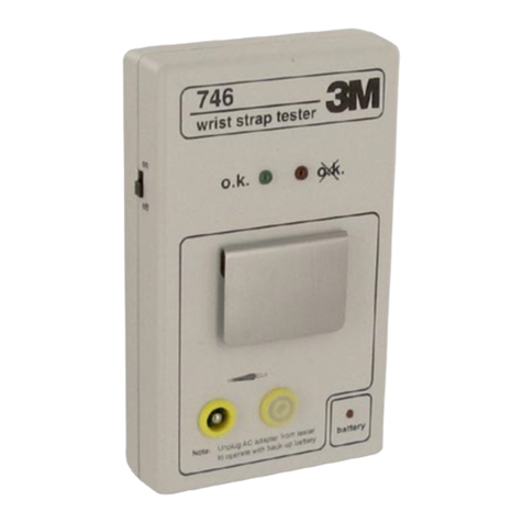
3M 746 User manual

3746
Wrist Strap Tester
Operating Instructions
746 3
wrist strap tester
o.k. o.k.
Listed

2
Safety Information
Intended Use
The 3M™ 746 Wrist Strap Tester was designed and tested to be used for
measuring the electrical resistance of single-conductor wrist strap assemblies.
General
The design of the 746 allows for testing of wrist straps while being
worn by a person or testing of the individual wrist strap components.
The 746 can be mounted to a wall or be used as a portable piece of test
equipment. It operates from a 120 Vac source through an AC adapter,
or a standard 9 volt battery. An internally set resistance range extends
from 750 KΩto 10 MΩ. If the wrist strap resistance when tested is
within this range, a green LED will illuminate. If outside this range,
a red LED will illuminate.
Wrist straps are the primary method used to minimize charge
generation on the human body. They must be able to drain this charge
as rapidly as it is generated. For this reason, it is important to test
wrist straps on a regular basis to ensure they are functioning properly.
The test results should be recorded. The form on page 9 of these
instructions can be used as a logbook.
Read and Understand all Safety Information Before
Operating this Equipment.
Explanation of Symbols
- Caution: read operating instructions.
- Warning: read operating instructions.
O.K. - See operating instructions for explanation of the indicator LED.
- See operating instructions for explanation of the indicator LED.
Battery

3
Battery Environmental
The ULTRALIFE
®
, U9VL-J battery contains no mercury, cadmium or lead.
Accessories:
- Instruction booklet
- Wall mounting kit (3M™ Dual Lock™ Wall Mounting System and template)
- Battery
- Cover for wrist strap plug-in jack
- AC/DC adapter
CAUTION
Battery Replacement:
The use of a NEDA 1604, 9 volt alkaline type battery is recommended
for the 3M 746 Wrist Strap Tester. For longer service life, use an
ULTRALIFE®, U9VL-J battery. The original battery supplied with the
746 is an ULTRALIFE brand battery. This battery is available through
Radio Shack®retail electronic stores, Catalog Number 23-665. For more
information about this battery or other retail outlets, contact ULTRALIFE
BATTERIES INC. at 1-800-332-5000.
Battery Disposal: Dispose of batteries in accordance with state and
local requirements.
WARNING
• Battery may explode if misused. Do not recharge or disassemble.
• Do not dispose of in fire.
• When replacing with lithium battery, use only ULTRALIFE, U9VL-J.
Use of another type lithium battery may present a risk of fire or explosion.
CAUTION
If the AC/DC adapter is plugged into the 746 Wrist Strap Tester, it must also
be plugged into the wall outlet to allow the unit to function. If the 746 tester is
to be powered with battery only, the AC/DC adapter MUST be disconnected
from the DC input jack (1B) on the tester.

4
Specifications
Base unit: 158 x 95 x 33 mm (6.25 x 3.75 x 1.25 in.)
Weight: 200g (7 oz.) without battery
Battery provided: 9 Vdc Lithium/Manganese Dioxide NEDA 1604LC
AC/DC Adapter: 9 Vdc regulated 75 mA
Accuracy: +/- 10% (10 MΩlimit)
+ 20%-0% (750 KΩlimit)
Measurement voltage: 19 Vdc +/- 1 Vdc (open circuit)
Environmental Operating Conditions:
Temperature:
Maximum 104° F / 40° C
Minimum 32° F / 0° C
Humidity:
Maximum 80% R.H.
Installation
THE PARAGRAPH NUMBERS BELOW ARE
REFERENCED ON THE DIAGRAM ON PAGE 7.
Power Sources
1A. 9 volt backup battery
Due to the slightly larger size of the long-life lithium battery, it is
necessary to properly locate the battery snap connector and wires in the
battery compartment. To correctly install the battery, follow these
instructions:
Attach the battery snap connector to the battery. Place the battery into
the compartment, locating the snap connector at the opposite end of the
compartment from where the battery wires come through the housing,
keeping the wires along the top edge of the compartment. Run the
battery wires along the side of the battery and tuck them down between
the housing and the battery so that the wires clear the cover. Use a
small, straight blade screwdriver to gently push the battery wires down
below the lip of the compartment. Slide and lock the cover into place.
When changing the battery, the battery cover must be removed
carefully. To remove the battery cover, slide back the cover slightly.
Insert a small, straight blade screwdriver into the opening immediately
over the tab area beneath the word “OPEN.” Press down with the
screwdriver while sliding the cover off. You must use a screwdriver
to remove the battery cover.
5
1B. AC/DC Adapter
Connect the AC/DC adapter to the jack at the base of the unit.
Plug the adapter into a 120 Vac outlet.
2. Battery Indicator
Jack Cover
3. Insert the plastic cover into the yellow wrist strap plug-in jack that is not
being used. The jack on the right fits standard banana plugs used in
North America. The 746 Wrist Strap Tester is now ready for use.
Wall Mounting
4. The enclosed 3M™ Dual Lock™ Wall Mounting System adhesion
discs must be screwed onto the wall, using the attached template,
approximately 1,5 m (5 ft.) off the floor. Drill three holes of 5 mm
(0.2 in.) diameter at marked locations.
5. The enclosed Dual Lock adhesion strip must be cut in two halves and
adhered to the rear of the 746 Tester, parallel to the bottom edge and
below the battery compartment. Make sure the area on the 746 Tester
where the adhesion strips are to be placed is free of dust and dirt.
Press the back of the case firmly against the discs to secure the tester
to the wall.
6. For removal, lift the 746 Wrist Strap Tester at the two top corners with
both hands.
CAUTION
If the AC/DC adapter is plugged into the 746 Wrist Strap Tester, it must
also be plugged into the wall outlet to allow the unit to function. If the
746 tester is powered with the battery only, the AC/DC adapter MUST
be disconnected from the DC input jack (1B) on the tester.
CAUTION
When operating on battery power only, replace the battery immediately
when the “Battery” indicator LED illuminates.

6
Testing Procedure
Wrist Band/Cord Test
7. Put the wrist band on with the ground cord attached and insert the
ground cord banana plug into the yellow wrist strap plug-in jack.
8. Depress the metal contact plate and hold.
9. One of the LED indicators will illuminate. An illuminated green LED
indicates that the wrist strap assembly performs within the resistance
range of 750 KΩto 10 MΩ. If a red LED is illuminated, the resistance
of the wrist strap assembly may be outside the range of 750 KΩto
10 MΩ. To check the resistance of the ground cord, leave the banana
plug end attached to the tester. Unsnap the cord from the wrist band.
Place the metal side of the ground cord snap end against the metal
contact plate. Depress the plate and check to see which LED
illuminates. If the red LED illuminates, the ground cord is outside
of the resistance range. If the green LED illuminates, the ground cord
is “OK” but the wrist band may need to be replaced.
NOTE: In some cases, a high contact resistance between the person’s skin and
the wrist band will cause the tester to indicate a red LED (greater than
10 MΩ
). This higher resistance may be caused by dry skin or hair
on the wearer's wrist. A loose fitting wrist band can also cause
intermittency or high resistance. If these conditions do not exist, a
new wrist band should be obtained and tested on the person.

7
746 3
wrist strap tester
o.k. o.k.
FIGURE 1
8
2
1B
3
7
6
4
1A
5
1,5 m
(5 feet)
9
Verification Procedure
The 746 Wrist Strap Tester cannot be adjusted by the user, but the
following steps can be used to verify that the 746 is operating within
its specification. (The 746 may also be returned to 3M to obtain
certification. Please call 800-328-1368 for more information.)
Equipment needed
1. Resistance substitution box, 700
KΩ
- 11 M
Ω
, accuracy < 2%.
2. Two lead wires to connect the resistance box to the 746 Tester.
Checking wrist strap test circuit
Connect the resistance substitution box to the tester as shown in
Figure 2.
Adjust the resistance substitution box to each value of resistance
indicated in the test table below and press contact plate A.
The LEDs will indicate, as shown below, if the unit is functioning
within specifications.

8
*This example is used in Figure 2
750 K
Ω
* 750 K
Ω
red
900 K
Ω
green
9.0 M
Ω
10 M
Ω
green
11.0 M
Ω
red
Resistance
substitution box
setting
Resistance range
of the tester LED indication
11.0 M
9.0 M
900 K
750 K
746 3
wrist strap tester
o.k. o.k.
A
Alligator Clip
Resistance Substitution Box
FIGURE 2

9
Test Parameters: min. 750K Ω
max. 10M Ω
Serial-No:
Name
Month / Year :
33746 Wrist Strap Tester Logbook

Electronic Handling and
Protection Division
6801 River Place Blvd.
Austin, TX 78726-9000
Important Notice
Before using this product, you must evaluate it and determine if it is suitable
for your intended application. You assume all risks and liability associated with
such use.
Warranty; Limited Remedy; Limited Liability.
This product will be free from defects in material and manufacture for a period of
(1) year from the date of purchase. 3M MAKES NO OTHER WARRANTIES
INCLUDING, BUT NOT LIMITED TO, ANY IMPLIED WARRANTY OF MER-
CHANTABILITY OR FITNESS FOR A PARTICULAR PURPOSE. If this product is
defective within the warranty period stated above, your exclusive
remedy shall be, at 3M’s option, to replace or repair the 3M product or refund the
purchase price of the 3M product. Except where prohibited by law, 3M will not be
liable for any loss or damage arising from this 3M product, whether direct, indirect,
special, incidental or consequential regardless of the legal theory asserted.
Litho in the USA
© 3M 1999 34-7048-1263-4
Recycled Paper
40% pre-consumer
10% post-consumer
Other manuals for 746
1
Table of contents
Other 3M Test Equipment manuals

3M
3M 701 User manual

3M
3M Clean-Trace UXL100 Instruction sheet

3M
3M PS200 Series Manual

3M
3M Dynatel 2273ME Series User manual

3M
3M Wireless Tire Pressure Monitoring System User manual

3M
3M Dynatel 965AMS-BT User manual

3M
3M 900AST Series User manual

3M
3M FT-10 Guide

3M
3M Clean-Trace AQF100 Instruction sheet

3M
3M FT-30 User manual