MSG MS111 User manual

MSG MS111
STANOWISKO DO DIAGNOSTYKI SPRĘŻAREK
KLIMATYZACJI SAMOCHODOWEJ
INSTRUKCJA OBSŁUGI
TEST BENCH FOR VEHICLE AIR
CONDITIONER COMPRESSORS
USER MANUAL
UNIQUENESS
QUALIT Y SERVICE
WARRANTY TRAINING
INNOVATION
2020.07.31
СТЕНД ДЛЯ ДИАГНОСТИКИ КОМПРЕССОРОВ
КОНДИЦИОНЕРОВ АВТОМОБИЛЯ
РУКОВОДСТВО ПО ЭКСПЛУАТАЦИИ


User Manual - Test Bench MS111
English
INTRODUCTION.......................................................................................................................................................2
1. PURPOSE.............................................................................................................................................................. 2
2. TECHNICAL CHARACTERISTICS.......................................................................................................................3
3. COMPLETE EQUIPMENT SET............................................................................................................................4
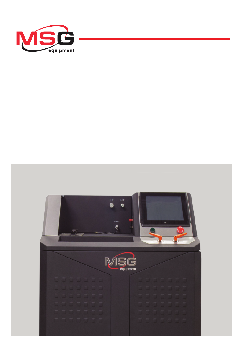
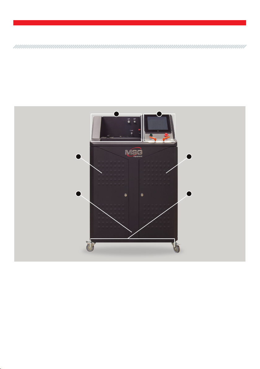
4. TEST BENCH DESCRIPTION............................................................................................................................. 5
5. INTENDED USAGE...............................................................................................................................................8
5.1 Safety regulations......................................................................................................................................9
5.2 Pre-starting procedures........................................................................................................................10
5.2.1 Equipment installation...................................................................................................................10
5.2.2 Test bench lling..............................................................................................................................11
5.2.3 Connection of cables to the test bench terminals................................................................12
6. TEST BENCH MAINTENANCE..........................................................................................................................13
6.1 Cleaning and care....................................................................................................................................14
6.2 Condensate draining..............................................................................................................................14
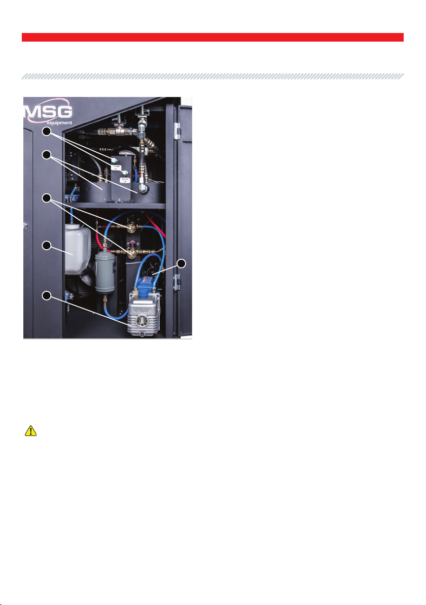
6.3 Replacement of lters in the test bench hydraulic system.......................................................15
6.4 Firmware update..................................................................................................................................... 19
7. MAJOR FAULTS AND TROUBLESHOOTING.................................................................................................19
8. DISPOSAL OF THE EQUIPMENT.................................................................................................................... 21
CONTENTS
1

Thank you for choosing the product by MSG Equipment.
The actual User Manual contains information on the purpose, equipment set, design, mode of
operation, technical characteristics and operating rules of MS111 test bench.
The manufacturer reserves the right to make changes to the equipment hardware and rmware
without prior notice to users.
It is strongly recommended to read carefully the actual User Manual before launching Test Bench
MS111 (hereinafter referred to as “the test bench”). Special training can be taken at the
manufacturing enterprise if necessary.
Test Bench is intended for testing piston, axial piston, rotor and scroll compressors of automotive
climate systems operating on refrigerants R134 and R1234yf.
The test bench performs the following operations:
•diagnostics of belt-driven vehicle AC compressors of all types with supply voltage of 12/24 V, in
both manual and automatic modes;
•diagnostics of electromagnetic clutches and valves separately from compressors;
•post-maintenance run of compressors;
•pre-sale testing of new analog compressors;
•test results save and printout (any external printer can be used).
INTRODUCTION
1. PURPOSE
2
User Manual - Test Bench MS111
English

2. TECHNICAL CHARACTERISTICS
3. CONTROL DEVICES
Supply voltage, V 400
Supply type Three-phase
Drive power, kW 5.5
Dimensions (L×W×H), mm 900×570×1280
Weight, kg 183
Drive speed, rpm from 0 to 3000
Drive speed adjustment Smooth / gradual
Utilized refrigerant R134a, R1234yf
Amount of refrigerant in the system, g R134a – 1100
R1234yf – 1050
Refrigerant ltration Yes (1 µm2)
Test bench lling Stand-alone lling station
Vacuum line of the unit Yes
Refrigerant pumping out of the unit Yes
Drive type Belt
V-belt / poly-V belt
Output parameters
HP, bar;
LP, bar;
Compr t, °С;
Evpr t, °С;
PWM %.
Type of lling ttings Automotive HP and LP
Amount of oil in the system, g 200
Utilized oil PAG46yf
Data printout Yes
Connection to the Internet Ethernet , Wi-Fi (802.11 a/b/g/ac)
3
User Manual - Test Bench MS111
English

Test Bench set includes:
Inspect the test bench. If any damage is found, please contact either the manufacture or the trade
representative before launching the equipment.
Item name Q-ty, pcs
Test Bench MSG MS111 1
Set of two quick-disconnect hoses 1
Compressor temperature sensor 1
Clamp bars (set of 3 pcs) 2
MS0101 – polypropylene lter element 2
MS0102 – lter element of electromagnetic valve 2
Set of ttings to connect the compressor to the test bench, no less than 8
Set of 4 cables for connection to the electromagnetic clutch and valve 1
MS0103 – rubber ring gasket O-02289 for sealing of interlocking parts of lter case 4
MS122 – Adapter for connecting compressors with 24V clutch 1
Stylus 1
Wi-Fi module 1
Test Bench door key 2
Power socket 380V 1
User Manual 1
3. EQUIPMENT SET
4
User Manual - Test Bench MS111
English

The test bench consists of the following major components (Fig.1): test bench housing - 1; door for
access to the power compartment - 2; mounting face - 3; control panel - 4; door for access to the
service compartment - 5; swivel wheels with a brake - 6.
All diagnostic procedures with the tested unit are performed on the mounting face. The mounting
face contains:
34
4. TEST BENCH DESCRIPTION
Figure 1 – Major components of the Test Bench
5
2 5
1 6
User Manual - Test Bench MS111
English

1 – Compressor drive belts: V-belt and Poly-V belt.
2 – Compressor xing chain.
3 – Dust cover. The diagnostic procedure is suspended when the cover is opened.
4 – Compressor temperature sensor.
5 – Connecting tting for low-pressure hose.
6 – Connecting tting for high-pressure hose.
7 – Compressor control valve connection terminals. Adherence to polarity is not necessary.
8 – Compressor electromagnetic clutch connection terminals. Adherence to polarity is not
necessary.
6
34 5 6
7
8
1
2
Figure 2 – Mounting face of the Test Bench
User Manual - Test Bench MS111
English

7
Control panel (Fig.3) includes the following elements:
1 – LP valve: low-pressure hose control.
2 – Start button “OFF/ON”: Test Bench power on/off. Button “OFF/ON” cannot be activated when
button “EMERGENCY STOP” is pressed.
3 – Touch screen: diagnostic data display and test bench control
4 – Button “EMERGENCY STOP”: emergency shutdown.
5 – HP valve: high-pressure hose control.
The back panel of the test bench (Fig.4) is equipped with a LAN port to connect the Test Bench to
the Ethernet and two USB ports to connect the Wi-Fi adapter (included in the equipment set) and
external printer.
3
2 4
1 5
1 2
Figure 3 – Control panel of the Test Bench
Figure 4 –Back panel of the Test Bench
User Manual - Test Bench MS111
English

The routine maintenance of the Test Bench is
essential for trouble-free enduring operation of
the equipment. A service compartment of the
bench (Fig.5) includes:
1 – Vacuum pump.
2 – Condensate tank.
3 – Electromagnetic valve lters.
4 – Main lter of the test bench hydraulic system.
5 – LP and HP lling ttings.
6 – Compressor for refrigerant pumping.
Figure 5 – Service compartment
of the Test Bench
5
8
1. The Test Bench should be used for intended purpose only (read Section 1).
2. The emergency switch (n.4, Fig.3) and button «ON/OFF» are used for emergency shut-down
only. In the regular operation mode, it is recommended to switch off the test bench through the
program interface by clicking on “Turn off bench”. Button «ON/OFF» should be pressed after the
display goes black.
3. Use a stylus (included in the equipment set) to avoid damage to the touch screen (n.3, Fig.3).
4. The use of inappropriate computer hardware or rmware will cause cancellation of the
warranty (even if the computer facilities or programs were removed or deleted shortly after). Only
the MSG Equipment original rmware can be used with this equipment.
5. INTENDED USAGE
WARNING! The Test Bench operates on refrigerants either R134a or R1234yf. It is strongly
recommended not to use other refrigerants. Oil PAG46yf must be used for the systems on
R1234yf and R134a.
4
3
2
1
6
User Manual - Test Bench MS111
English

5. Any modication to the equipment except for that, made by the ofcial manufacturer, is
prohibited. The use of the equipment is allowed only with its original component parts and
accessories. The non-observance of this point will cause removal of the warranty liability.
6. To avoid damage to the Test Bench or its failure, do not make any changes to the equipment
on your own. In case of malfunction, contact the manufacturer or sales representative.
MSG Equipment will not be responsible for any damage resulted from improper operation of the
equipment.
ATTENTION! The procedure for diagnostics of compressors with the Test Bench is described
in operation manual. Download from the appropriate product detail page on servicesm.eu.
1. The Test Bench should only be used by the persons qualied to operate the test benches of
certain types who received a special training in the equipment safety operation.
2. Before the unit dismounting from the test bench, the refrigerant should be evacuated.
3. Either in case of power failure or emergency, or before the equipment cleaning and servicing,
press button "ON/OFF" to switch the Test Bench off.
4. The workplace should be clean, well-lit and spacious.
5. The use of the faulty or unearthed Test Bench is strictly prohibited.
6. The compressor mounting and/or dismounting should be conducted carefully to prevent its
fall.
7. The unit with the running drive may not be left on the test bench unattended.
8. It is strictly forbidden to open the door of the power compartment (n. 2, Fig.1) when the test
bench is connected to 400V power supply.
9. Avoid body contact with the refrigerant, it may lead to a frostbite (R134a boiling point is -26°С,
R1234yf boiling point is -30°С).
10. It is strongly recommended to use protective gloves and glasses.
11. Any refrigerant is a colorless and odorless gas which is heavier than air. Entering the
atmosphere, it can cause asphyxiation or heart rhythm disorders. That is why, the Test Bench
should be used in well-ventilated premises only. The available exhaust units in the room must be
switched on.
5.1 Safety regulations
9
User Manual - Test Bench MS111
English

12. Refrigerant R-1234yf is a highly ammable gas. Take extra care when working with this
refrigerant.
13. Open ame sources are allowed nowhere near the test bench operating area. Smoking near
the Test Bench is prohibited. A regular re-extinguishing appliance is a must.
14. If the protective caps of the lling ttings cannot be easily unscrewed, there is a risk of injury
due to the valves poor tightness.
5.2 Preparation of the Test Bench for use
5.2.1 Placement location and installation
10
User Manual - Test Bench MS111
English

11
The Test Bench is delivered to a customer charged with refrigerant R134a for 10-15% and with a
full charge of oil. To ensure the Test Bench performance, it is necessary to ll the hydraulic
system up to the standard level. The required amount of the refrigerant is specied in the chart
“Technical characteristics” (Item 2 of the Manual).
Relling of the hydraulic system with the refrigerant should be performed as follows:
1. Open the door of the service compartment (n.5, Fig.1) with a special key (included in the
equipment set).
2. There are two ttings for relling of the test bench hydraulic system: «Service LP» and «Service
HP» (n.5, Fig.5).
3. Connect the lling station lines to the test bench ttings. High-pressure and low-pressure
valves (n.1,5, Fig. 3) located on the control panel (Fig.3) should be in the closed position (OFF).
4. Pump the refrigerant out of the hydraulic system.
5. Dehydrate the system to remove the air and moisture residues. To do this, take the lling
station off into the air pumping mode. Stop pumping on reaching the pressure of -0.9 Bar.
6. Upon the vacuuming procedure completion, non-condensable impurities must be removed
from the lling station in the following manner:
6.1. Disconnect the lling station line from the Test Bench.
6.2. Remove the non-condensed impurities through a special valve (Fig.6) as prescribed in the
corresponding Manual for the lling station.
WARNING! Relling of the Test Bench directly from a container with the refrigerant is strictly
prohibited as it can lead to emergency situations.
WARNING! Use specialized equipment for evacuation and purication of the refrigerant
R134a and system relling. Observe the instructions set out in the corresponding User Manual.
WARNING! It is necessary to control the amount of oil released together with the refrigerant
since the same amount of it should be added when relling.
5.2.2 Relling of the Test Bench
User Manual - Test Bench MS111
English

7. Connect the lines of the lling station to the Test Bench. Fill the bench with the necessary
amount of the refrigerant and oil.
8. Upon completion, disconnect the lling station lines. Place protective caps on the ttings for
better tightness. Close the door of the service compartment with a special key.
WARNING! In cases when R1234yf must be used in the Test Bench, the evacuation of R134a
from the system is required. The evacuation time should be extended for 10 min from the rated
time. To ll the bench with refrigerant R1234yf, follow the procedure described in User Manual
for the lling station and the information specied above.
To perform the diagnostics and control of the compressor electromagnetic clutch or valve,
connect either Adapter MS122 or the appropriate cables to the test bench terminals as shown in
the connection diagram (Fig.7). Adherence to the electric polarity is not necessary
5.2.3 Connection of the cables to the Test Bench terminals
Figure 6 – Discharge valve of the lling station
12
User Manual - Test Bench MS111
English

13
Figure 7 – Connection of the cables (Adapter MS122)
to the test bench terminals «Clutch» and «Valve»
The Test Bench is intended for a long-term use under twenty-four-hour schedule. For awless
operation of the equipment it is necessary to inspect the Test Bench as recommended and
observe the below-described preventive measures. Inspection and maintenance of the bench
should be performed by qualied specialists.
Special attention should be paid to the following points of the daily inspection:
• Proper operation of the motor (no unusual sounds, vibration, etc.).
• Suitable environmental conditions for the equipment operation (temperature, humidity, air
pollution concentration, vibration, etc.).
• Maintenance of supply voltage within the allowable range (based on the voltmeter readings).
• Condensate tank charge level: if the tank is full, it should be emptied. The procedure is described
in Item 6.2 of the Manual.
When the Test Bench requires servicing, the following messages may be displayed on the screen:
“Too much air in the system”: relling of the Test Bench is required (see Item 5.2.2).
6. TEST BENCH MAINTENANCE
User Manual - Test Bench MS111
English

14
Most common error causes:
incorrect lling of the bench, insufcient or excess amount of the refrigerant in the system;
•leaky system;
•ingress of air into the system when an unpressurized compressor is being tested;
•high room temperature.
•Recovery methods:
•if the message appeared during operation of the bench in manual mode, two recovery options
are available: 1 – Set the pressure at maximum and repeat the test; 2 – Reduce the speed of the
evaporator fan.
•make sure that the requirements for the equipment placement and installation have been
observed (Item 5.2.1 of the Manual).
•rell the Test Bench with the refrigerant (Item 5.2.2)
“Condensate tank is full”: empty the tank. The procedure is described in Item 6.2 of the Manual.
“Replace lter”: lter replacement is required (n.4 Fig.5). The procedure is described in Item 6.3
of the Manual.
Clean the test bench surface with neutral detergents using soft tissues or wiping cloth. Use
special ber tissue and spray to clean the display. The use of abrasives or solvents may cause
failure or damage to the test bench.
Drain the condensate from the tank as follows:
1. Disconnect the bench from the power supply.
2. Open the door of the service compartment (n.5 Fig.1) with a special key (included in the
equipment set)
3. Unscrew the tank cap (n.3, Fig.8).
6.1 Cleaning and Care
6.2 Condensate draining
User Manual - Test Bench MS111
English

15
4. Disconnect the condensate level sensor (n.2 Fig.8)
5. Remove the tank from the test bench by pushing it upward.
6. Empty the tank.
7. Reinstall the tank, reconnect the sensor, put the tank cap on and screw it up.
2
1
2
Figure 8 – Removal of the condensate tank
1 – tank; 2 – connector of the condensate level sensor; 3 – tank cap
Observe the actual diagram and Chart 1 for replacement of the lters:
–each message «Replace lter» should be followed by replacement of the right lter element
MS0101 (Fig.9);
– every other replacement of the right lter element MS0101 should be followed by replacement
of the left lter element MS0101;
– every forth replacement of the left lter element MS0101 should be followed by replacement of
both lter elements MS0102 (Fig.13);
6.3 Replacement of lters in the hydraulic
system of the Test Bench
PUT ON
REMOVE
User Manual - Test Bench MS111
English

16
SCREW IN
LEFT FILTER RIGHT FILTER
SCREW IN
UNSCREW
UNSCREW
Figure 9 – Direction of lter cover rotation during lter replacement MS0101
Right MS0101 + + + + + + + + ...
Left MS0101 + + + + ...
Two lters
MS0102 + ...
Chart 1. Frequency of lter replacements in the Test Bench.
The procedure of lter MS0101 (n.4, Fig.5, Fig.9-11) replacement is as follows:
1. Put both valves (HP and LP) in “OFF” position and disconnect the bench from the power supply.
2. Open the service compartment door (n.5, Fig.1) with a special key (included in the equipment
set).
3. Pump the refrigerant out using a special service station for air conditioners.
5. Level the inside pressure of the Test Bench with the atmospheric pressure by pressing the valve
of the lling port. Even a slight pressure difference will make it much more difcult to unscrew
the lter cup.
6. Turn the lter cover (n.1, Fig.10) counter-clockwise (Fig.9) with either a hook wrench or a socket
wrench until the lter bowl is free.
6. Check the condition of O-rings (n.3, Fig.10) and replace if necessary.
WARNING! Since the compression oil is hygroscopic and absorbs moisture from the air, lter
elements MS0101 and MS0102 should be reinstalled as quickly as possible.
User Manual - Test Bench MS111
English

7. Replace the lter element MS0101 (n.2 Fig. 10).
8. Reinstall the lter cover and screw it clockwise until tight (see Fig.9).
9. Close the door of the test bench service compartment (n.5 Fig.1).
10. Rell the Test bench with the refrigerant (Item 5.2.2).
2
1
3
Figure 10 – Refrigerant lter structure
1 – lter cover; 2 – lter element MS0101; 3 – O-rings
Figure 11 – Filter element MS0101
17
User Manual - Test Bench MS111
English

18
Figure 13 – Direction of the cover rotation when replacing lter MS0102
Figure 12 – Filter element MS0102
It is recommended to replace lter elements MS0102 of electromagnetic valves together
with lter elements MS0101.
SCREW IN
SCREW IN
UNSCREW
UNSCREW
User Manual - Test Bench MS111
English
Other manuals for MS111
2
Table of contents
Languages:
Other MSG Test Equipment manuals