dB CNX User manual

CNX MAINTENANCE
INTERFACE PANEL
USER'S MANUAL
(Version 2.0)
www.db-integrations.com

CNX MAINTENANCE INTERFACE PANEL USER'S MANUAL
Version 2.0
Table f Contents:
Maintenance Panel Overview:......................................................................................3
User's Manual Applicability:........................................................................................3
Equipment Part Numbers:............................................................................................3
Physical Speci ications:.................................................................................................3
Inter aces and Power:....................................................................................................3
Console Connections:.....................................................................................................3
Panel Connector Pinouts:..............................................................................................4
Powering On/O The Panel and CNX-200 Router:...................................................8
CNX Input Discretes:....................................................................................................8
Contact Us:.....................................................................................................................9
Warranty:.......................................................................................................................9
Page 2

CNX MAINTENANCE INTERFACE PANEL USER'S MANUAL
Version 2.0
Maintenance Panel verview:
The CNX Maintenance Interface Panel (MIP) is a custom made, rack mounted unit with
the abilit to break out most interfaces available on the Honeywell CNX-200 (-20)
Router. The unit fits into a standard 19” rack with a 2RU height.
User's Manual Applicability:
Unit Hardware Version Unit So tware Version
Version 3 Version 1.2
Equipment Part Numbers:
Description Part Number
CNX-200 MIP DB10-200-01
Physical Specifications:
Satcom Direct Router Maintenance Inter ace Panel
Physical Speci ications
Part Number: DB10-1100-01
Dimensions: 19” wide x 3.70” tall x 9.50” deep
Power: 120-240VAC (50-60 HZ)
Interfaces and Power:
The CNX Maintenance Interface Panel communicates with the CNX-200 Router via
three CPC connectors on the back side with custom made harnesses. Connections to a
PC are established through either the DB9 female connectors or the provided RJ45
jacks, depending on communication t pe. It gets powered b a built-in 24VDC power
suppl capable of driving 5 amps.
Console Connections:
The Maintenance Interface Panel incorporates 2ea. DB9 connectors labeled “EXPAND”
and “ROUTER” to interface a PC to the CNX-200's maintenance and Expand consoles.
Page 3

CNX MAINTENANCE INTERFACE PANEL USER'S MANUAL
Version 2.0
Panel Connector Pinouts:
J1, 9 pin male CPC
TE Connectivity, P/N: 206486-1
Mates With:
TE Connectivity, P/N: 206485-1
Pin P/N: M39029/63-368 pins
Backshell:
TE Connectivity, P/N: 1-206062-6
Pin 1
24VDC Switched Output ( tied to pins 2 & 3)
Pin 2
24VDC Switched Output ( tied to pins 1 & 3)
Pin 3
24VDC Switched Output ( tied to pins 1 & 2)
Pin 4
No Connection
Pin 5
No Connection
Pin 6
No Connection
Pin 7
24VDC Return (tied to pins 8 & 9)
Pin 8
24VDC Return (tied to pins 7 & 9)
Pin 9
24VDC Return (tied to pins 7 & 8)
J2, 63 pin male CPC
TE Connectivity, P/N: 206455-2
Mates With:
TE Connectivity, P/N: 205482-1
Pin P/N: M39029/63-368 pins
Backshell:
TE Connectivity, P/N: 182930-1
Pin 1 Soft Reset Discrete
Pin 2 Factor Reset Discrete
Pin 3 WiFi Discrete
Pin 4 Router DB9, Pin 3
Pin 5 LAN Ethernet Port 1, Pin 2
Pin 6 LAN Ethernet Port 1, Pin 1
Pin 7 Soft Reset Reference
Pin 8 Discrete Reference
Pin 9 Router DB9, Pin 2
Pin 10 Router DB9, Pin 5
Page 4
CNX MAINTENANCE INTERFACE PANEL USER'S MANUAL
Version 2.0
Pin 11 No Connection
Pin 12 LAN Ethernet Port 1, Pin 6
Pin 13 LAN Ethernet Port 1, Pin 3
Pin 14 LAN Ethernet Port 3, Pin 2
Pin 15 LAN Ethernet Port 3, Pin 1
Pin 16 LAN Ethernet Port 2, Pin 6
Pin 17 LAN Ethernet Port 2, Pin 3
Pin 18 LAN Ethernet Port 2, Pin 1
Pin 19 LAN Ethernet Port 2, Pin 2
Pin 20 LAN Ethernet Port 3, Pin 6
Pin 21 LAN Ethernet Port 3, Pin 3
Pin 22 LAN Ethernet Port 5, Pin 2
Pin 23 LAN Ethernet Port 5, Pin 1
Pin 24 LAN Ethernet Port 4, Pin 6
Pin 25 LAN Ethernet Port 4, Pin 3
Pin 26 LAN Ethernet Port 4, Pin 2
Pin 27 LAN Ethernet Port 4, Pin 1
Pin 28 Ethernet Port 7, Pin 6 (WAN 2)
Pin 29 Ethernet Port 7, Pin 2 (WAN 2)
Pin 30 Ethernet Port 7, Pin 1 (WAN 2)
Pin 31 LAN Ethernet Port 6, Pin 6
Pin 32 LAN Ethernet Port 6, Pin 3
Pin 33 LAN Ethernet Port 6, Pin 2
Pin 34 LAN Ethernet Port 6, Pin 1
Pin 35 LAN Ethernet Port 5, Pin 6
Pin 36 LAN Ethernet Port 5, Pin 3
Pin 37 Ethernet Port 7, Pin 3 (WAN 2)
Pin 38 No Connection
Pin 39 No Connection
Pin 40 No Connection
Pin 41 WAN Ethernet Port 1, Pin 6
Pin 42 WAN Ethernet Port 1, Pin 3
Page 5
CNX MAINTENANCE INTERFACE PANEL USER'S MANUAL
Version 2.0
Pin 43 WAN Ethernet Port 1, Pin 1
Pin 44 WAN Ethernet Port 1, Pin 2
Pin 45 ISDN Port 1, Pin 6
Pin 46 ISDN Port 1, Pin 3
Pin 47 ISDN Port 1, Pin 4
Pin 48 ISDN Port 1, Pin 5
Pin 49 ISDN Port 2, Pin 6
Pin 50 ISDN Port 2, Pin 3
Pin 51 ISDN Port 2, Pin 4
Pin 52 ISDN Port 2, Pin 5
Pin 53 No Connection
Pin 54 ISDN Port 3, Pin 4
Pin 55 ISDN Port 3, Pin 5
Pin 56 ISDN Port 4, Pin 3
Pin 57 ISDN Port 4, Pin 6
Pin 58 ISDN Port 4, Pin 4
Pin 59 ISDN Port 4, Pin 5
Pin 60 No Connection
Pin 61 No Connection
Pin 62 ISDN Port 3, Pin 3
Pin 63 ISDN Port 3, Pin 6
Page 6

CNX MAINTENANCE INTERFACE PANEL USER'S MANUAL
Version 2.0
J3, 28 pin emale CPC
TE Connectivity, P/N: 206038-1
Mates With:
TE Connectivity, P/N: 206039-1
Pin P/N: M39029/64-369 pins
Backshell:
TE Connectivity, P/N: 182661-1
Pin 1 Expand DB9, Pin 8
Pin 2 Expand DB9, Pin 7
Pin 3 Expand DB9, Pin 6
Pin 4 Expand DB9, Pin 5
Pin 5 Expand DB9, Pin 4
Pin 6 Expand DB9, Pin 3
Pin 7 Expand DB9, Pin 2
Pin 8 Expand DB9, Pin 1
Pin 9 Expand DB9, Pin 9
Pin 10-28 No Connection
Page 7
CNX MAINTENANCE INTERFACE PANEL USER'S MANUAL
Version 2.0
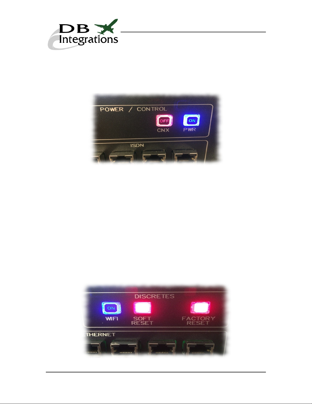
Powering n/ ff The Panel and CNX-200 Router:
Plug the Maintenance Interface Panel into a 110-220VAC (50-60Hz) power source.
Initiate power b pressing the “PWR” button located at the top, right hand side of the
panel face. Once turned on, the CNX-200 router's 24VDC power can now be toggled b
pressing the “CNX” button.
CNX Input Discretes:
The Maintenance Interface Panel has three buttons to control the CNX-200 router's
WiFi, soft reset, and factor reset discretes. The CNX-200 can be controlled b using
the following buttons:
The “WIFI” button toggles the CNX-200 router's wireless discrete. When indicated as
“ON” and illuminated blue, pins J2-3 and J2-8 are open. When indicated as “OFF” and
illuminated red, these pins are shorted together. B default, the unit powers up with
these pins open (wireless on).
The “FACTORY RESET” button activates the CNX-200 router's factor reset discrete.
When pressed and held, it will illuminate blue and short pins J2-2 and J2-8 together.
The “SOFT RESET” button activates the CNX-200 router's reset discrete. When
pressed and held, it will illuminate blue and short pins J2-1 and J2-7 together.
Page 8

CNX MAINTENANCE INTERFACE PANEL USER'S MANUAL
Version 2.0
Contact Us:
Please feel free to contact us if ou need an additional help with the operation of this
device.
DB Integrations, LLC
3405 Airport Road
Allentown, PA 18109
Phone: (610) 443-0201
Fax: (732) 486-0211
Email: [email protected]
Web: www.db-integrations.com
Warranty:
DB Integrations offers a 1 ear warrant on an malfunction of this device that does not
relate to abuse. Technicians are available during normal working hours to help diagnose
and approve units for return should the become defective. See contact information
above. Warrant information is tracked internall b sales figures.
Page 9
Table of contents
Popular Recording Equipment manuals by other brands

Besantek
Besantek BST-CT101 instruction manual

Amperes
Amperes TD6080 instruction manual

Emcotec
Emcotec RC Electronic DPSI BMS operating manual

Fostex
Fostex X-15 Multitracker Service manual

UTC AEROSPACE SYSTEMS
UTC AEROSPACE SYSTEMS Rosemount Aerospace 8730L Series user manual

Phonocar
Phonocar 05958 installation instructions


