DBI SALA Saflok 2100100 User manual

SPECIFIC INSTRUCTIONS48
© Copyright 2011, DB Industries, Inc.
A Capital Safety Company
3EN 795:1996
50 Class: B
8
CE TYPE TEST
No. 0320
TUV NEL
East Kilbride,
Glasgow
G75 0QU
UK
9
CE PRODUCTION
QUALITY CONTROL
No. 0086
BSI Product Services
Kitemark House
Mayland Ave.
Hemel Hempstead
HP2 4SQ UK
2
50
10
9
3
3
5.6 cm
7.6 cm
22.2 cm
10.2 cm
3.8 cm
x1
#= 49
5902392
#= 48
3
1
Component: 62 Material: 18
G
C
DI
E
F
H
J
B
A
ASwivel Ring 2Zinc Covered
Forged Steel 27
BLabel 1Vinyl 11
CTrigger 3Aluminum 23
DRelease Plug 4Zinc Covered
Steel 27
EEnd
Termination 5Stainless
Steel 26
FWedges 6Stainless
Steel 26
GMain Cable 7Galvanized
Steel 25
HSpacer 8Stainless
Steel 26
IBumper 9
JRetractor
Cables 10 Galvanized
Steel 25
FORM NO: 5903000
REV: B
SAFLOK®
Concrete Wedge Anchor
Model Number: 2100100
1
78

3
FORWARD: This instruction describes installation and use of the Saok®Concrete Wedge Anchor. It should be
used as part of an employee training program as required by CE.
IMPORTANT: Before using this equipment, record the product identication information from the Installation
and Service Label on the Equipment Identication Sheet at the back of the “General Instructions for Use and
Maintenance” (5902392).
5902392
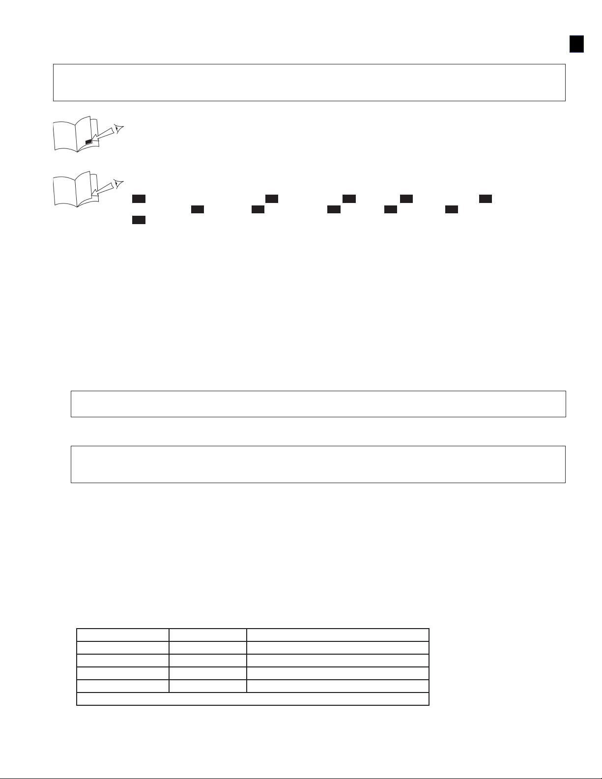
GENERAL GLOSSARY REFERENCE BOXES: White Glossary Reference
Boxes on the front cover of this instruction reference ‘Glossary’ items in the
“General Instructions for Use and Maintenance” (5902392).
3
SPECIFIC GLOSSARY REFERENCE BOXES: Black Glossary Reference Boxes on the front
cover of this instruction reference the following items:
1: Concrete Wedge Anchor 2: Swivel Ring 3: Trigger 4: Release Plug 5: End
Termination 6: Wedges 7: Main Guide 8: Spacer 9: Bumper 10: Retractor Cables
11: Vinyl
DESCRIPTION: The Saok®Concrete Wedge Anchor (Figure 1) is a reusable anchor point for horizontal, vertical,
or overhead concrete applications. The anchor’s End Termination (1E) expands Wedges (1F) to secure the anchor
in a 20 mm (or 3/4 in.) mounting hole. A spring-tensioned Trigger (1C) and Retractor Cables (1J) release the
Wedges to allow immediate removal and relocation to another hole. A Swivel Ring (1A) serves as the connection
for Fall Arrest, Work Positioning, Restraint, or Personnel Riding systems.
PURPOSE: The Concrete Wedge Anchor is designed for use as a component of a Personal Fall Arrest System
(PFAS). PFASs are used where free fall is possible before the fall is arrested and typically include: a Self Retracting
Lifeline (EN 360) or Energy Absorbing Lanyard (EN 355); connector (EN 362) to attach to the anchor; and a Full
Body Harness (EN 361).
REQUIREMENTS: Installation and use of this equipment is restricted to the following limitations:
• Capacity: The Concrete Wedge Anchor is designed for use by persons with a combined weight (clothing, tools,
etc.) of no more than 141 kg. No more than one personal protective system may be connected at one time.
NOTE: For emergency rescues it may be acceptable to connect more than one system if the anchorage will
support the anticipated loads.
• Maximum Arresting Force: PFAS used with this equipment must meet applicable EU CE requirements. The
PFAS must be capable of arresting the user’s fall with a maximum arresting force of 6 kN.
WARNING: Mark or label the Concrete Wedge Anchor with the intended application. Use of this equipment
for an application that does not meet the anchorage strength requirement stated above may result in
serious injury or death.
• Connections: When using a hook to connect to the Concrete Wedge Anchor, ensure roll-out cannot occur.
Connecting hardware must be a Carabiner or 16kN (3,600 lbs) Self-locking Snap Hook.
INSTALLATION REQUIREMENTS: The following requirements must be observed to ensure safe effective
installation of the Concrete Wedge Anchor:
A. Concrete: The concrete in which the anchor is secured must have a compressive strength of 20.7 MPa
(3,000 psi). The Concrete Wedge Anchor is not intended for use in lightweight concrete, hollow block, grout,
stone, wood, steel, or any other substrate. The concrete base material must be at least 12.7 cm thick.
B. Mounting Hole Location: The allowable distance from an edge or corner for mounting the
Concrete Wedge Anchor will vary with the thickness and width of the concrete. Mounting hole location
requirements are as follows:
Concrete Thickness: Concrete Width: Minimum Mounting Distance from Edge/Corner:
30.5 cm 30.5 cm 15.3 cm
25.4 cm 40.6 cm 20.3 cm
20.3 cm 50.8 cm 25.4 cm
12.7 cm 61.0 cm 30.5 cm
NOTE: Drill bits for drilling mounting holes must conform to CE requirements.
EN

4
INSTALLATION: To ensure effective installation of the Concrete Wedge Anchor, always observe the Installation
Requirements dened in the previous section. Perform the following steps to install the Concrete Wedge Anchor.
Refer to Figure 1 for component identication:
Step 1. Drill a 7.62 cm (3 in.) or deeper hole at the desired mounting location with a Rotary Hammer and
industrial grade 20 mm (or 3/4 in.) Rotary Hammer Drill Bit.
WARNING: Before drilling holes, inspect the hole location to prevent drilling into power transmission
cables or other live utilities.
Step 2. The mounting hole must be free of debris for the Concrete Wedge Anchor to develop maximum
anchorage. Blow all debris out of the hole with a Blow-Out Bulb or Compressed Air. If you are reusing an
existing hole, inspect thoroughly for debris and a uniform surface.
Step 3. Place your thumb in the anchor Swivel Ring (1A) and pull up on the Trigger (1C) with two ngers until
fully retracted.
Step 4. Insert the anchor into the mounting hole until the Release Plug (1D) seats against the concrete surface
and then release the Trigger (1C).
Step 5. Pull up on the anchor Swivel Ring (1A) to set the anchor.
REMOVAL: To release the Concrete Wedge Anchor, push down on the Release Plug (1D) and pull up on the
Trigger (1C). If the anchor does not release, tap the Release Plug (1D) and repeat the process.
REUSE: The Concrete Wedge Anchor may be reused if it has not been subjected to a fall force.
DISPOSAL: Dispose of the Concrete Wedge Anchor if it has been subjected to fall force or Inspection reveals an
unsafe or defective condition. Before disposing of the Concrete Wedge Anchor, cut the Wedges off the Retractor
Cables (1J) to eliminate the possibility of inadvertent reuse.
INSPECTION FREQUENCY: To ensure safe, efcient operation, the Concrete Wedge Anchor should be inspected
at the following intervals:
• Before Each Use: Visually inspect the Concrete Wedge Anchor per the Inspection steps dened in the next
section.
• Annually: A formal inspection of the Concrete Wedge Anchor and its connection to the structure
must be performed at least annually by a competent person other than the user. The frequency
of formal inspections should be based on conditions of use or exposure. See the next section for
Inspection steps. Record the inspection results in the Periodic Examination and Repair History in the
“General Instructions for Use and Maintenance” (5902392).
IMPORTANT: Extreme working conditions (harsh environment, prolonged use, etc.) may require increasing the
frequency of inspections.
INSPECTION: Per the intervals dened in in the previous section, inspect the Concrete Wedge Anchor as follows.
(Refer to Figure 1 for component identication):
Step 1. Make sure the Concrete Wedge Anchor is straight and is operating smoothly.
Step 2. Make sure the Label (1B) is attached to the Concrete Anchor and is legible (see Figure 2).
Step 3. Make sure the Main Cable (1G) and Retractor Cables (1J) are not kinked, frayed, or damaged.
Step 4. Make sure metal components are not damaged or excessively corroded.
Step 5. Make sure the Wedges (1F) and Retractor Cables (1J) operate smoothly and no metal burrs are present.
Ensure Wedges (1F) do not exhibit any deformities.
NOTE: Record the inspection date and results in the Periodic Examination and Repair History in the “General
Instructions for Use and Maintenance” (5902392). If inspection reveals a defect, remove the anchor form
service and dispose in the mannner indicated in the “Disposal” section.
CLEANING: After each use, blow off the Concrete Wedge Anchor with compressed air. Keep the anchor free of
grease, oils, and dirt.
STORAGE: Store the Concrete Wedge Anchor in a clean dry environment. Avoid areas where chemical vapors
may exist. Do not pile objects on top of the anchor. Thoroughly inspect the Concrete Wedge Anchor after extended
storage.
SPECIFICATIONS: See the front cover for materials (Figure 1) and physical dimensions (Figure 3).

5
AVANT-PROPOS : Cette notice décrit la procédure d'installation et d'utilisation du goujon d'ancrage pour béton
Saok®. Elle doit être utilisée dans le cadre de la formation d'un employé, tel que requis par les normes CE.
IMPORTANT : Avant d'utiliser cet équipement, consigner les informations d'identication du produit se trouvant
sur l'étiquette d'installation et d'entretien sur la che d'identication à la n du « Mode d'emploi et d'entretien
général » (5902392).
5902392
RENVOIS AU GLOSSAIRE GÉNÉRAL : Les renvois en blanc au glossaire de la
page de couverture de cette notice correspondent aux éléments « Glossaire » du
“General Instructions for Use and Maintenance” (5902392)
3
RENVOIS SPÉCIFIQUES AU GLOSSAIRE : Les renvois en noir au glossaire de la page de
couverture de cette notice correspondent aux éléments suivants :
1: Goujon d'ancrage pour béton 2: Anneau articulé 3: Déclencheur 4: Bouchon de
retrait 5: Pièce de terminaison 6: Goujons 7: Guide principal 8: Entretoise
9: Butoir 10 : Câbles de rétraction 11 : Vinyle
DESCRIPTION : Le goujon d'ancrage pour béton Saok®(Figure 1) est un point d'ancrage réutilisable pour
applications de béton horizontales, verticales ou en surplomb. La pièce de terminaison (1E) de l'ancrage étend les
goujons (1F) pour sécuriser l'ancrage dans un trou de montage de 20 mm. Un déclencheur à ressort (1C) et des
câbles de rétraction (1J) libèrent les goujons pour permettre un retrait immédiat et un repositionnement sur un
autre trou. Un anneau articulé (1A) sert à raccorder les systèmes anti-chute, de positionnement pour le travail, de
retenue ou de harnais personnels.
OBJECTIF : Le goujon d'ancrage pour béton est conçu pour être utilisé comme élément d’un système antichute
personnel (PFAS). Ces systèmes sont utilisés là où des risques de chute libre peuvent se produire et incluent
généralement : une ligne de vie auto-rétractable (norme EN 360) ou une longe à absorption d'énergie (norme EN
355), un connecteur (norme EN 362) xé à l'ancrage et un harnais complet (norme EN 361).
EXIGENCES : Il est indispensable de respecter les limitations suivantes lors de l’installation et de l’utilisation de
cet équipement :
• Capacité : Ce goujon d'ancrage pour béton est destiné à un usage par des personnes dont le poids total
(poids corporel, vêtements, outils, etc.) ne dépasse pas 141 kg. Un seul dispositif de protection personnel
peut être raccordé à la fois.
REMARQUE : Pour les interventions de sauvetage, plusieurs systèmes peuvent être raccordés si l’ancrage
peut supporter les charges anticipées.
• Force d’arrêt maximale : Les systèmes antichute personnels utilisés avec cet équipement doivent répondre
aux exigences des réglementations européennes. Le système antichute personnel doit être capable d’arrêter
une chute de l’utilisateur avec une force d’arrêt maximale de 6 kN.
AVERTISSEMENT : Marquer ou libeller le goujon d'ancrage pour béton pour indiquer l'application à laquelle
il est destiné. L’utilisation ce matériel pour une application ne répondant pas aux forces d’ancrage stipulées
ci-dessus peut causer des blessures graves ou la mort.
• Raccordements : En cas d'utilisation d'un crochet pour raccorder le goujon d'ancrage pour béton, s'assurer
qu'aucun détachement ne peut se produire. Le dispositif de raccordement doit être un mousqueton standard
ou un mousqueton à pression autobloquant à 16 kN.
CONSIGNES D'INSTALLATION : Les conditions suivantes doivent être respectées pour assurer une installation
sûre et efcace du goujon d'ancrage pour béton :
A. Béton : Le béton dans lequel l'ancre est sécurisé doit posséder une résistance à la compression minimum
de 20,7 MPa. Le goujon d'ancrage pour béton n’est pas conçu pour être utilisé sur du béton léger, des blocs
creux, de la brique, du coulis, de la pierre, du bois, du métal ou tout autre substrat. La matière de base du
béton doit posséder une épaisseur minimum de 12,7 cm.
B. Emplacementdesoricesdexation: La distance autorisée d'un bord ou d'un coin pour l'installation
du goujon d'ancrage pour béton dépendra de l'épaisseur et de la largeur du béton. Les conditions
d'emplacement des orices de xations sont les suivantes :
Épaisseur du béton : Largeur du béton : Distance de fixation minimale d'un bord/coin :
30,5 cm 30,5 cm 15,3 cm
25,4 cm 40,6 cm 20,3 cm
20,3 cm 50,8 cm 25,4 cm
12,7 cm 61,0 cm 30,5 cm
REMARQUE : Les forets utilisés pour réaliser les trous de montage doivent être conformes aux exigences CE.
FR
Table of contents
Languages:


