DBI SALA 2100180 Operator's manual

© Copyright 2014, Capital Safety
FORM NO: 5903698
REV: B
ROOF TOP COUNTERWEIGHT ANCHOR SYSTEM 2100180
OR 2100185 WITH LIFTING KIT 2104190
The Ultimate in Fall Protection
Figure 1 - Assembled Roof Top Counterweight Anchor System with Lifting Kit
1
3
5
4
2
6
7
Important: This instruction 5903698 must
be used when assembling and using the Roof
Top Counterweight Anchor System 2100180
(CE model) or 2100185 (ANSI/CSA model) in
combination with Lifting Kit 2104190. Do not
use instruction 5903602 or 5903726 which are
intended for assembling and using the Roof
Top Counterweight Anchor system 2100180 or
2100185 without Lifting Kit 2104190.
If you intend to add the Lifting Kit 2104190 to
an already-assembled Roof Top Counterweight
Anchor System 2100180 or 2100185, the Roof
Top Counterweight Anchor System must be
completely disassembled and then reassembled
by following this instruction 5903698.
1- Roof Top Anchor 2- ID Label 3- U-Bolts (4) 4- Lifting Kit Bracket (4) 5- Black Rubber Coated Base Weights
6- Counterweights 7- Lifting Kit Webbing (4)
WARNING: These instructions must be provided to the user of this equipment. The user must read and understand these instructions
before using this equipment. Manufacturer’s instructions must be followed for proper use and maintenance of this equipment. The user
must follow the manufacturer’s instructions for each component of the system. Alterations or misuse of this product or failure to follow
instructions may result in serious injury or death.
IMPORTANT: If you have questions on the use, care, or suitability of this equipment for your application, contact Capital Safety.
IMPORTANT: 3ULRUWRLQVWDOODWLRQDQGXVHRIWKLVHTXLSPHQWUHFRUGWKHSURGXFWLGHQWL¿FDWLRQLQIRUPDWLRQIURPWKH,'ODEHOLQWKH
Inspection and Maintenance Log at the back of this manual.
USER INSTRUCTION MANUAL

1.0 PRODUCT APPLICATION
1.1 PURPOSE: The oo To o nter ei ht nchor tem i e i ne or e a an anchorin mean or a er onal all
DUUHVWV\VWHP3)$6IRUDSHUVRQZRUNLQJRQÀDWURRIVRUVWUXFWXUHV7KH/LIWLQJ.LWLVGHVLJQHGWRDOORZWUDQVSRUWRID
IXOO\DVVHPEOHG5RRI7RS&RXQWHUZHLJKW$QFKRU6\VWHPEHWZHHQORFDWLRQVRQDMREVLWH,WLVQRWLQWHQGHGIRUWUDQVSRUWRI
DQFKRUV\VWHPVEH\RQGDMREVLWHRUIRUPRYHPHQWRIDQ\RWKHUHTXLSPHQWRUPDWHULDO
WARNING: Unless otherwise noted, Capital Safety equipment is designed for use with Capital Safety approved components and
subsystems only. Substitution or replacement with non-approved components or subsystems may jeopardize compatibility of equipment
and may affect safety and reliability of the complete system. Do not hang, lift, or support tools or equipment from the Anchorage
System, or attach guy lines for antennas, phone lines, etc.
1.2 SUPERVISION:,QVWDOODWLRQRIWKLVHTXLSPHQWPXVWEHVXSHUYLVHGE\D4XDOL¿HG3HUVRQ 8VHRIWKLVHTXLSPHQWPXVWEH
er i e a om etent Per on
1.3 TRAINING:7KLVHTXLSPHQWPXVWEHLQVWDOOHGDQGXVHGE\SHUVRQVWUDLQHGLQLWVFRUUHFWDSSOLFDWLRQ7KLVPDQXDOLVWREH
XVHGDVSDUWRIDQHPSOR\HHWUDLQLQJSURJUDPDVUHTXLUHGE\26+$,WLVWKHUHVSRQVLELOLW\RIWKHXVHUVDQGLQVWDOOHUVRI
thi e i ment to en re the are amiliar ith the e in tr ction traine in the correct care an e o thi e i ment
an are a are o the o eratin characteri tic a lication limitation an con e ence o im ro er e o thi
HTXLSPHQW
IMPORTANT: Training must be conducted without exposing the user to a fall hazard. Training should be repeated periodically.
1.4 RESCUE PLAN: hen in thi e i ment an connectin tem the em lo er m t ha e a re c e lan an the
mean at han to im lement an comm nicate that lan to er thori e Per on an e c er $WUDLQHGRQ
VLWHUHVFXHWHDPLVUHFRPPHQGHG7HDPPHPEHUVVKRXOGEHSURYLGHGZLWKWKHHTXLSPHQWDQGWHFKQLTXHVWRSHUIRUPD
VXFFHVVIXOUHVFXH7UDLQLQJVKRXOGEHSURYLGHGRQDSHULRGLFEDVLVWRHQVXUHUHVFXHUSUR¿FLHQF\
1.5 INSPECTION FREQUENCY:
The
oo To o nter ei ht nchor tem
hall e in ecte the er e ore each
e an a itionall a om etent Per on other than the er at inter al o no more than one ear ,QVSHFWLRQ
SURFHGXUHVDUHGHVFULEHGLQ6HFWLRQRIWKLVPDQXDO5HVXOWVRIHDFK&RPSHWHQW3HUVRQLQVSHFWLRQVKRXOGEHUHFRUGHGLQWKH
“Inspection and Maintenance Log”LQWKLVPDQXDO
1.6 AFTER A FALL:,IWKH5RRI7RS&RXQWHUZHLJKW$QFKRU6\VWHPLVVXEMHFWHGWRWKHIRUFHVRIDUUHVWLQJDIDOOLWPXVWEH
UHPRYHGIURPWKH¿HOGRIVHUYLFHLPPHGLDWHO\DQGUHSODFHGRULQVSHFWHGE\DQ$XWKRUL]HG&DSLWDO6DIHW\5HSUHVHQWDWLYH
1.7 LIMITATIONS:7KHIROORZLQJOLPLWVDSSO\WRWKHLQVWDOODWLRQDQGXVHRI5RRI7RS&RXQWHUZHLJKW$QFKRU6\VWHP2WKHU
limitation ma a l
A. HORIZONTAL LIFELINE: The oo To o nter ei ht nchor tem i not rate or e a an anchor or a
KRUL]RQWDOOLIHOLQH
B. SYSTEM CAPACITY: The ma im m ca acit o the oo To o nter ei ht nchor tem i one er on ith a
PD[LPXPFRPELQHGZHLJKWLQFOXGLQJWRROVDQGFORWKLQJRIOEVNJ
C. ROOF TYPES: The oo To o nter ei ht nchor tem i a ro e or e on the ollo in t e o roo
FRQFUHWHDVSKDOWVDQGHGDQGDVSKDOWVWRQHFKLSSLQJV,I\RXZDQWWRXVHWKHV\VWHPRQDQ\RWKHUW\SHRIURRILQJ
VXUIDFHFRQWDFW'%,6$/$IRUIXUWKHUUHFRPPHQGDWLRQV
D. ROOF LOAD:7KHURRIPXVWEHDEOHWRVXSSRUWDVWDWLFORDGRIOEV
E. ROOF CONDITIONS:7KH5RRI7RS&RXQWHUZHLJKW$QFKRU6\VWHPPXVWQRWEHXVHGLQDGYHUVHZHDWKHUFRQGLWLRQV
The roo r ace m t e ree o ro t no tan in ater rea e or oil or an other t e o l ricatin or riction
UHGXFLQJPDWHULDOV
F. PERSONAL FALL ARREST SYSTEM: PF e ith thi roo anchor m t meet a lica le tate e eral
DQG$16,UHTXLUHPHQWV3)$6VLQFRUSRUDWLQJDIXOOERG\KDUQHVVPXVWEHFDSDEOHRIDUUHVWLQJDZRUNHU¶VIDOOZLWKD
PD[LPXPDUUHVWLQJIRUFHRIQRJUHDWHUWKDQOEVN1DQGOLPLWWKHIUHHIDOOGLVWDQFHWRIWPRUOHVV
7KHGHFHOHUDWLRQGLVWDQFHIRUD3)$6PXVWEHLQFKHVPRUOHVVLQFKHVPLQ&DQDGD5HIHUHQFH
$16,=26+$DQG&6$=UHTXLUHPHQWV7KHV\VWHPPXVWEHULJJHGLQDZD\WKDWOLPLWVIUHHIDOOWRIW
RUOHVV&RQWDFW'%,6$/$LI\RXKDYHTXHVWLRQVRUFRQFHUQVUHJDUGLQJIUHHIDOOOLPLWV
G. ENVIRONMENTAL HAZARDS: 8VHRIWKLVHTXLSPHQWLQDUHDVZKHUHHQYLURQPHQWDOKD]DUGVH[LVWPD\UHTXLUH
DGGLWLRQDOSUHFDXWLRQVEHWDNHQWRUHGXFHWKHSRVVLELOLW\RILQMXU\WRWKHXVHURUGDPDJHWRWKHHTXLSPHQW+D]DUGV
ma incl e t are not limite to hi h heat e treme col ca tic chemical corro i e en ironment hi h olta e
SRZHUOLQHVH[SORVLYHRUWR[LFJDVHVPRYLQJPDFKLQHU\RUVKDUSHGJHV&RQWDFW'%,6$/$LI\RXKDYHTXHVWLRQV
DERXWXVLQJWKLVHTXLSPHQWZKHUHHQYLURQPHQWDOKD]DUGVH[LVW
4XDOL¿HG3HUVRQ$SHUVRQZLWKDUHFRJQL]HGGHJUHHRUSURIHVVLRQDOFHUWL¿FDWHDQGZLWKH[WHQVLYHNQRZOHGJHWUDLQLQJDQGH[SHULHQFHLQWKHIDOOSURWHFWLRQ
DQGUHVFXH¿HOGZKRLVFDSDEOHRIGHVLJQLQJDQDO\]LQJHYDOXDWLQJDQGVSHFLI\LQJIDOOSURWHFWLRQVDQGUHVFXHV\VWHPVWRWKHH[WHQWUHTXLUHGE\26+$DQGRWKHU
applicable standards.
&RPSHWHQW3HUVRQ2QHZKRLVFDSDEOHRILGHQWLI\LQJH[LVWLQJDQGSUHGLFWDEOHKD]DUGVLQWKHVXUURXQGLQJVRUZRUNLQJFRQGLWLRQVZKLFKDUHXQVDQLWDU\
KD]DUGRXVRUGDQJHURXVWRHPSOR\HHVDQGZKRKDVDXWKRUL]DWLRQWRWDNHSURPSWFRUUHFWLYHPHDVXUHVWRHOLPLQDWHWKHP
$XWKRUL]HG3HUVRQ For purposes of the Z359 standards, a person assigned by the employer to perform duties at a location where the person will be exposed
to a fall hazard.
5HVFXHU Person or persons other than the rescue subject acting to perform an assisted rescue by operation of a rescue system.
,QVSHFWLRQ)UHTXHQF\([WUHPHZRUNLQJFRQGLWLRQVKDUVKHQYLURQPHQWVSURORQJHGXVHHWFPD\UHTXLUHLQFUHDVLQJWKHIUHTXHQF\RIFRPSHWHQWSHUVRQ
inspections.

2.0 SYSTEM REQUIREMENTS
2.1 CONNECTOR COMPATIBILITY: onnector are con i ere to e com ati le ith connectin element hen the
ha e een e i ne to or to ether in ch a a that their i e an ha e o not ca e their ate mechani m
WRLQDGYHUWHQWO\RSHQUHJDUGOHVVRIKRZWKH\EHFRPHRULHQWHG&RQWDFW&DSLWDO6DIHW\LI\RXKDYHDQ\TXHVWLRQVDERXW
FRPSDWLELOLW\
&RQQHFWRUVKRRNVFDUDELQHUVDQG'ULQJVPXVWEHFDSDEOHRIVXSSRUWLQJDWOHDVWOEVN1&RQQHFWRUV
PXVWEHFRPSDWLEOHZLWKWKHDQFKRUDJHRURWKHUV\VWHPFRPSRQHQWV'RQRWXVHHTXLSPHQWWKDWLVQRWFRPSDWLEOH1RQ
FRPSDWLEOHFRQQHFWRUVPD\XQLQWHQWLRQDOO\GLVHQJDJHVHH)LJXUH,IWKHFRQQHFWLQJHOHPHQWWRZKLFKDVQDSKRRNRU
cara iner attache i n er i e or irre lar in ha e a it ation co l occ r here the connectin element a lie a orce
WRWKHJDWHRIWKHVQDSKRRNRUFDUDELQHU)LJXUH$7KLVIRUFHPD\FDXVHWKHJDWHWRRSHQ)LJXUH%DOORZLQJWKH
VQDSKRRNRUFDUDELQHUWRGLVHQJDJHIURPWKHFRQQHFWLQJSRLQW)LJXUH&
6HOIORFNLQJVQDSKRRNVDQGFDUDELQHUVDUHUHTXLUHGE\$16,=26+$DQG&6$=LQ&DQDGD
2.2 MAKING CONNECTIONS:6QDSKRRNVDQGFDUDELQHUVXVHGZLWKWKLVHTXLSPHQWPXVWEHVHOIORFNLQJ(QVXUHDOO
FRQQHFWLRQVDUHFRPSDWLEOHLQVL]HVKDSHDQGVWUHQJWK'RQRWXVHHTXLSPHQWWKDWLVQRWFRPSDWLEOH(QVXUHDOO
FRQQHFWRUVDUHIXOO\FORVHGDQGORFNHG
&DSLWDO6DIHW\FRQQHFWRUVVQDSKRRNVDQGFDUDELQHUVDUHGHVLJQHGWREHXVHGRQO\DVVSHFL¿HGLQHDFKSURGXFW¶VXVHU¶V
LQVWUXFWLRQV
([DPSOHVRILQDSSURSULDWHFRQQHFWLRQVDUHVKRZQLQ)LJXUH'RQRWFRQQHFWVQDSKRRNVDQGFDUDELQHUV
$ 7RD'ULQJWRZKLFKDQRWKHUFRQQHFWRULVDWWDFKHG
% ,QDPDQQHUWKDWZRXOGUHVXOWLQDORDGRQWKHJDWH
NOTE:/DUJHWKURDWVQDSKRRNVVKRXOGQRWEHFRQQHFWHGWRVWDQGDUGVL]H'ULQJVRUVLPLODUREMHFWVZKLFKZLOO
UHVXOWLQDORDGRQWKHJDWHLIWKHKRRNRU'ULQJWZLVWVRUURWDWHVXQOHVVWKHVQDSKRRNFRPSOLHVLVHTXLSSHGZLWK
DOEN1JDWH&KHFNWKHPDUNLQJRQ\RXUVQDSKRRNWRYHULI\WKDWLWLVDSSURSULDWHIRU\RXUDSSOLFDWLRQ
& ,QDIDOVHHQJDJHPHQWZKHUHIHDWXUHVWKDWSURWUXGHIURPWKHVQDSKRRNRUFDUDELQHUFDWFKRQWKHDQFKRUDQG
ZLWKRXWYLVXDOFRQ¿UPDWLRQVHHPVWREHIXOO\HQJDJHGWRWKHDQFKRUSRLQW
' 7RHDFKRWKHU
( 'LUHFWO\WRZHEELQJRUURSHODQ\DUGRUWLHEDFNXQOHVVWKHPDQXIDFWXUHU¶VLQVWUXFWLRQVIRUERWKWKHODQ\DUGDQG
FRQQHFWRUVSHFL¿FDOO\DOORZVVXFKDFRQQHFWLRQ
) To an o ect hich i ha e or imen ione ch that the na hoo or cara iner ill not clo e an loc or that
UROORXWFRXOGRFFXU
* ,QDPDQQHUWKDWGRHVQRWDOORZWKHFRQQHFWRUWRDOLJQSURSHUO\ZKLOHXQGHUORDG
Figure 2 - Unintentional Disengagement Figure 3 - Inappropriate Connections
$ % & '
( ) *
2.3 STRUCTURE LOAD:7KHVWUXFWXUHVXSSRUWLQJWKHVHDQFKRUDJHSRLQWVPXVWEHULJLGÀDWSLWFKDQGFDSDEOHRIVXSSRUWLQJ
DWOHDVWOEVN1LQWKHGLUHFWLRQRISRWHQWLDOIDOODUUHVW

.0 ASSEM LY AND USE
WARNING: Do not alter or intentionally misuse this equipment. Consult with D I-SALA if using the oof Top Counterweight
Anchor System in combination with components or subsystems other than those described in this manual. Some subsystems
and components combinations may interfere with the proper operation of this equipment. Use caution when using this
equipment around moving machinery, electrical and chemical hazards, and sharp edges.
WARNING: or ing at height has inherent ris s. Some ris s are noted here but are not limited to the following falling,
suspension prolonged suspension, stri ing objects, and unconsciousness. In the event of a fall arrest and or subsequent
UHVFXHHPHUJHQF\VLWXDWLRQVRPHSHUVRQDOPHGLFDOFRQGLWLRQVPD\DIIHFW\RXUVDIHW\0HGLFDOFRQGLWLRQVLGHQWL¿HGDVULVN\
for this type of activity include but are not limited to the following heart disease, high blood pressure, vertigo, epilepsy, drug
or alcohol dependence, psychiatric illness, impaired limb function and balance issues. e recommend that your employer
SK\VLFLDQGHWHUPLQHLI\RXDUH¿WWRKDQGOHQRUPDODQGHPHUJHQF\XVHRIWKLVHTXLSPHQW
3.1 BEFORE
EACH USE in ect thi e i ment accor in to te li te in ection o not e the
oo To o nter ei ht
nchor tem
i in ection re eal an n a e or e ecti e con ition Plan o r e o the all rotection tem rior to
e o in or er to an ero it ation on i er all actor a ectin o r a et e ore in thi tem
A. ea an n er tan all man act rer in tr ction or each com onent o the er onal all arre t tem
ll harne e an connectin tem are lie ith e arate er in tr ction ee all in tr ction
or t re re erence
B. e ie ection an to en re tem limitation an other re irement ha e een a here to e ie
a lica le in ormation re ar in tem clearance criteria an en re chan e ha e not een ma e to the tem
in tallation i e len th or occ rre at the o ite that co l a ect the re ire all clearance o not e the
tem i chan e are re ire
3.2 PLAN o r all arre t tem e ore tartin o r or Ta e into con i eration actor a ectin o r a et at an time
rin e The ollo in li t i e ome im ortant oint o m t con i er hen lannin o r tem
A. ANCHORAGE: elect an anchora e oint that i ri i an ca a le o ortin the re ire loa ee ection
ocate the roo anchor in accor ance ith ection
B. OTHER CONSIDERATIONS:
Place the oo To o nter ei ht
nchor tem at lea t t m
a a rom an e e or o enin ee
Fi re
3HUVRQDOIDOODUUHVWV\VWHPVPXVW
e ri e to limit an ree all to a
ma im m o t m an
ee ection F
$YRLGZRUNLQJDERYH\RXUDQFKRUDJH
le el ince an increa e ree all i tance
ill re lt
$YRLGZRUNLQJZKHUH\RXUOLQHPD\FURVV
or tan le ith that o another or er or
another o ect
'RQRWDOORZWKHOLIHOLQHWRSDVVXQGHU
arm or et een le
1HYHUFODPSNQRWRURWKHUZLVHSUHYHQW
the li eline rom retractin or ein ta t
a oi lac line
Figure 4 - Counter eig t S stem Positioning
t m
learance t m min
oo To o nter ei ht
nchor tem o itionin
one
IMPORTANT: Do not lengthen the S L by connecting a lanyard or similar component without consulting D I-SALA.
C. TOTAL FALL DISTANCE: ho l a all occ r there m t e at lea t t o clearance in the all area to arre t the
all e ore tri in the ro n or other o ect ee Fi re The total all i tance i the i tance mea re rom
the on et o a all to the oint here the all i arre te n m er o actor can in l ence the total all i tance
incl in er ei ht anchora e location relati e to the all in all o ort ith li in rin an the
t e o all arre t e i ment o attach to the oo To o nter ei ht nchor tem U er m t a t m
into all clearance calc lation to acco nt or an mo ement in the co nter ei ht anchor a e hile arre tin a all
For eci ic clearance re irement rea an ollo the man act rer in tr ction or o r all arre t e i ment
D. S ING FALLS: ee Fi re in all occ r hen the anchora e oint i not irectl a o e the oint here a all
occ r The orce o tri in an o ect hile in in hori ontal ee o the er e to the en l m a ect can
e reat an ma ca e erio in r in all can e minimi e or in a clo e to the anchora e oint a
o i le n a in all it ation the total ertical all i tance o the er ill e reater than i the er ha allen
erticall irectl elo the anchora e oint The er m t there ore acco nt or an increa e in the total ree all
i tance an the area nee e to a el arre t the all
The i a lica le ill acti ate loc re ar le o it orientation an location relati e to the er o ition
ho e er a commonl ollo e i eline i or a irectl et een the anchora e oint an roo e e a o i le
o not ca ti ate the li eline o an it ma a ect the er ormance o it ra in a in all ha ar e i t in
o r a lication contact e ore rocee in
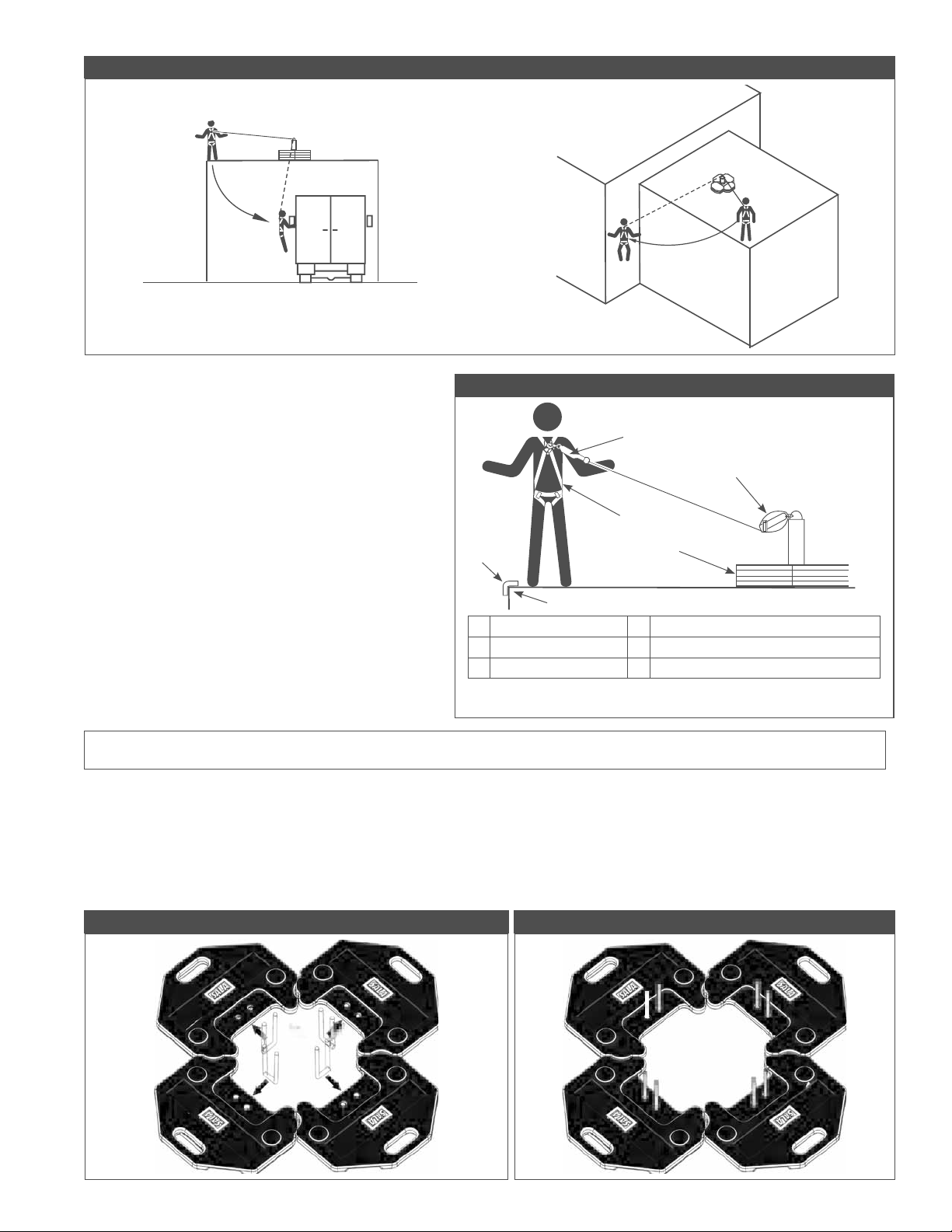
Figure 5 - S ing Falls
Une ecte a ar
in Fall a ar
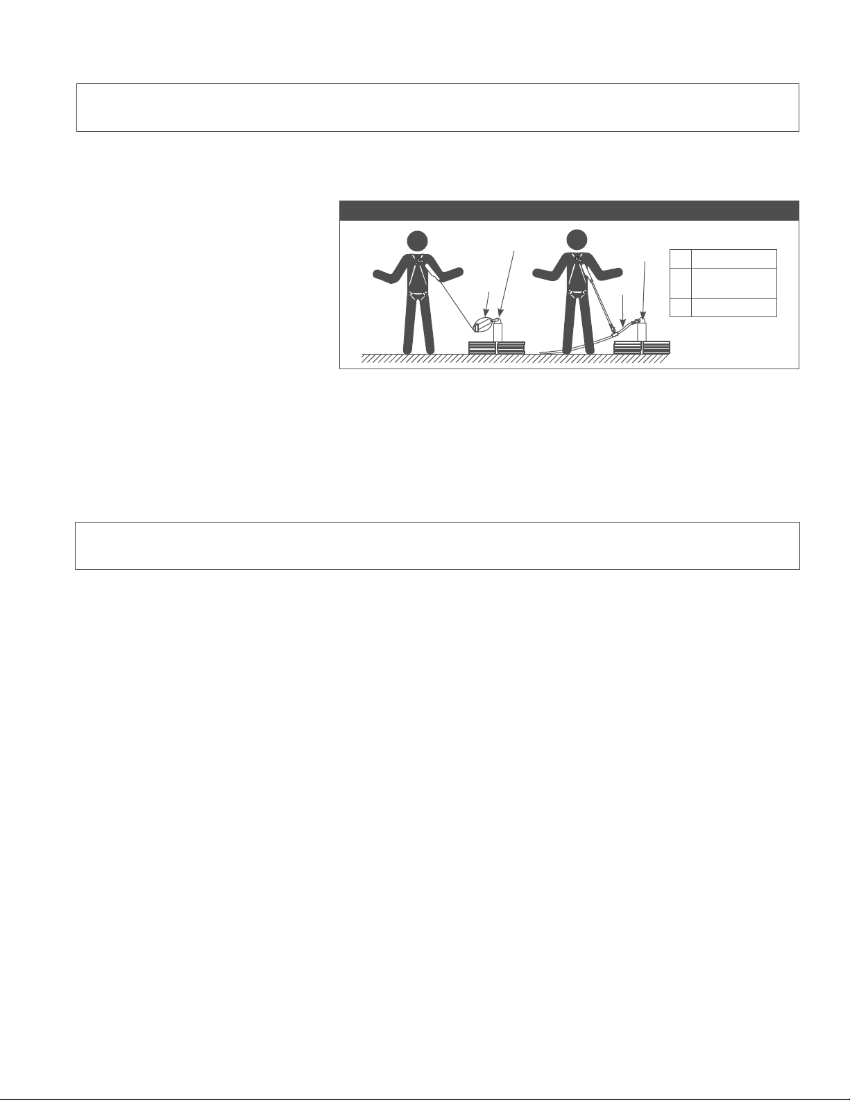
E. SHARP EDGES: oi or in here the
connectin tem i e ll o
harne lan ar li eline etc or other
tem com onent ill e in contact ith
or a ra e a ain t n rotecte har e e
ee Fi re or in ith thi e i ment
near har e e i na oi a le rotection
a ain t c ttin m t e ro i e in
a hea a or other mean o er the
e o e har e e o are not in
a ea in e it i recommen e
that an ener a or er P e
in talle in line et een the harne an the
el retractin li eline to rther rotect the
or er om ati ilit an total all i tance
i e m t e con i ere i thi i one
ontact e ore in in line ener
a or in com onent or lan ar ith el
retractin li eline
Figure 6 - S arp E ges
har e F ll o arne
Pa in oo To o nter ei ht nchor tem
n line hoc or er F
F
WARNING: ead and follow the manufacturer s instructions for associated equipment i.e. S L, full body harness, lanyard,
lifeline, etc. used in your personal fall arrest system.
3.3 SYSTEM ASSEMBLY: Fi re ho the a em le oo To o nter ei ht nchor tem ith i tin it
Step 1. 'HWHUPLQHDVXLWDEOHORFDWLRQIRUDVVHPEO\RIWKH5RRI7RS&RXQWHUZHLJKW$QFKRU6\VWHP,WPXVWEHÀDWDQG
at lea t t m a a rom the e e o the tr ct re or an o enin ch a li ht ee Fi re
Step 2. 6ZHHSWKHLQVWDOODWLRQORFDWLRQWRUHPRYHORRVHPDWHULDOV/D\RXWIRXUUXEEHUFRDWHGEDVHZHLJKWVRQWKHÀDW
r ace a ho n in Fi re U olt ill e in erte thro h the t o hole in each o the a e ei ht
Step 3. i t each a e ei ht an rom the ottom o the ei ht in ert a U olt thro h the t o hole in each ei ht
a ho n in Fi re
Figure 7 - La Out Base eig ts an U-Bolts Figure - Insert U-Bolts in Base eig ts

Step 4.
,QVHUW8EROWWKURXJKHDFKFRUQHURIWKHEDVHSODWH%DVHSODWHPXVWOLHÀDWRQWKHEDVHZHLJKWV6HH)LJXUH
Step 5. tac t o a itional ei ht on each a e ei ht ith the U olt rotr in thro h the matchin hole in
each ei ht ee Fi re
Figure - Insert U-Bolts T roug Base Plate Figure 1 - Stac T o eig ts on eac Base eig t
Step 6. Po ition the oo To nchor on the U olt an ei ht at a e ree an le to the a e late that a
re io l in talle a e re each U olt a e thro h one o the mo ntin hole in the oo To nchor
a e late ee Fi re
Step 7. an a itional la er o ei ht total o i teen ei ht are e in the oo To o nter ei ht nchor
tem ach o the o r ei ht tac ill contain o r ei ht a e ei ht l three a itional ei ht in
each tac ee Fi re
Figure 11 - Place Roo Top Anc or on U-Bolts Figure 12 - Final La er o eig ts
Step . Po ition each o the o r i tin it lin rac et at the en o the i tin it lin tra o er the U olt a
VKRZQLQ)LJXUH(DFKEUDFNHWÀDQJHPXVWEHSRVLWLRQHGRYHUWKHHGJHRIWKHZHLJKWEHORZLW,QVWDOOD
a her an a n t on each o the U olt en Ti hten all ei ht n t to t l
Step . oo a connector rate or a li tin o l or reater thro h the to o the tra a em l
here the o r i tin it tra are oine n ert the connector ia onall o that t o tra are on each
i e o the connector ee Fi re The oo To o nter ei ht nchor tem i no rea or tran ort
e o the i tin it ee Fi re or an e am le o i tin it connection to a hoi t tem ith a e ate
li tin ca acit U e ca tion hen tran ortin the tem
Figure 13 - Place Li ting Kit Brac ets on U-Bolts Figure 14 - Rea to Transport
3.4 BODY SUPPORT: hen in the oo To o nter ei ht nchor tem it i recommen e that a ll o
harne e orn For eneral all rotection e connect to the rin on the ac et een the ho l er or al rin
IMPORTANT: ody belts are not allowed for free fall situations. ody belts increase the ris of injury during fall arrest in
comparison to a full body harness. Limited suspension time and the potential for improperly wearing a body belt may result in
added danger to the user s health.
3.5 CONNECTING TO THE ROOF TOP ANCHOR: Fi re ill trate ro er connection o t ical all arre t e i ment
to the i elin in at the center o the oo To nchor l a rotect the li eline rom a ra in a ain t har or
a ra i e r ace on the roo a e re all the connection are com ati le in i e ha e an tren th e er connect
more than one er onal rotecti e tem to an in le oo To nchor
SRL: onnection to the in talle
riatech nchor ma e ma e
attachin the el loc in na hoo at
the en o the li eline to the ac
or al rin all arre t attachment
oint o the er o ort i e
ll o harne hen connectin
ma e re the connection are ll
clo e an loc e e ie ection i
in an near har e e
Figure 15 - Connections to Roo Top Counter eig t Anc or S stem
oo To
nchor in
ertical i eline
ENERGY ABSORBING LANYARDS OR LIFELINE: onnect the ener a or in en o the lan ar to the ac rin on the
ll o harne ee ection ee man act rer in tr ction or more in ormation
3.6 NORMAL OPERATION: nce attache the or er i ree to mo e a o t ithin the recommen e or in area
SRL: ho l a all occ r a ee en in ra e tem ill acti ate to in the all an a or in m ch o the ener
create en or ic mo ement ho l e a oi e rin the normal or o eration ince thi ma ca e the
to loc
ENERGY ABSORBING LANYARD: a all occ r the ener a or er ith e lo to the all an a or m ch o the
ener create
IMPORTANT: If the oof Top Counterweight Anchor System is subjected to the forces of arresting a fall, it must be
UHPRYHGIURPWKH¿HOGRIVHUYLFHLPPHGLDWHO\DQGUHSODFHGRULQVSHFWHGE\DQ$XWKRUL]HG&DSLWDO6DIHW\5HSUHVHQWDWLYH6HH
Section 5. .
.0 INSPECTION
5.1 BEFORE EACH ANCHOR SYSTEM INSTALLATION OR HEN REPOSITIONING THE ANCHOR SYSTEM: n ect the
co nter ei ht com onent an other tem com onent accor in to the e or other man act rer in tr ction tem
FRPSRQHQWVPXVWEHIRUPDOO\LQVSHFWHGE\D4XDOL¿HG3HUVRQRWKHUWKDQWKHXVHUDWOHDVWDQQXDOO\)RUPDOLQVSHFWLRQV
ho l concentrate on i i le i n o eterioration or ama e to the tem com onent tem o n to e e ecti e
m t e re lace o not e com onent i in ection re eal an n a e or e ecti e con ition ecor re lt o each
in ection in the Inspection And Maintenance Log in thi man al
5.2 INSPECTION STEPS:
Step 1. hec the co nter ei ht or e ce i e ent or e ormation hec the a e ei ht or elamination o the
r er coatin the coatin ha loo e e e that ma catch or o le ac on it el the a e ei ht ho l
e re lace
Step 2. n ect the nchor Po t an a e or h ical ama e oo care ll or an i n o crac ent or
e ormitie in the metal the nchor ha een ecte to all arre t orce the ri ht o t ill e ti e
o er to one i e o not e an nchor that ha een ecte to all arre t orce
Step 3. n ect the oo To o nter ei ht nchor tem or i n o e ce i e corro ion
Step 4. n re that the U olt an n t are in oo con ition an ti htene ec rel
Step 4. n ect the i tin it lin tra or i n o ra in or e aration
Step 5. n re the con ition o the roo ill ort the oo To o nter ei ht nchor tem loa ee ection
5.3 in ection re eal an n a e or e ecti e con ition remo e the nit rom er ice an e tro or contact or
o i le re air or art re lacement
5.4 USER EQUIPMENT: n ect each tem com onent or tem i e ll o harne lan ar li eline etc
er a ociate man act rer in tr ction e er to man act rer in tr ction lie ith each tem com onent or
in ection roce re
.0 MAINTENANCE SER ICE STORAGE
6.1 The oo To o nter ei ht nchor tem an i tin it com onent re ire no che le maintenance other than
re air or re lacement o item o n e ecti e rin in ection ee ection com onent ecome hea il oile
ith rea e aint or other tance clean ith a ro riate cleanin ol tion o not e ca tic chemical that co l
ama e tem com onent

.0 SPECI ICATIONS
7.1 MATERIALS:
Base eig t: er coate ca t iron
Counter eig ts: al ani e ca t iron
U- olts: al ani e teel
Li ting Kit Strap e ing: Pol e ter
Li ting Kit Strap Brac ets: inc late teel
7.2 EIGHT:
Eac Counter eig t: l
Li ting Kit: l
.0 LA ELING
.1 The e la el m t e re ent an ll le i le
On t e Roo Top Anc or ee Fi re item or la el location
On t e Li ting Kit la el e n into one o the i tin it lin tra
LIMITED LIFETIME ARRANTY
arrant to En User: n trie nc a P T F T U P T F T arrant to the
ori inal en er n U er that it ro ct are ree rom e ect in material an or man hi n er
normal e an er ice Thi arrant e ten or the li etime o the ro ct rom the ate the ro ct i
rcha e the n U er in ne an n e con ition rom a P T F T a thori e i tri tor
P T F T entire lia ilit to n U er an n U er e cl i e reme n er thi arrant i limite
to the re air or re lacement in in o an e ecti e ro ct ithin it li etime a P T F T in it ole
i cretion etermine an eem a ro riate o oral or ritten in ormation or a ice i en P T
6$)(7<LWVGLVWULEXWRUVGLUHFWRUVRI¿FHUVDJHQWVRUHPSOR\HHVVKDOOFUHDWHDQ\GLIIHUHQWRUDGGLWLRQDO
arrantie or in an a increa e the co e o thi arrant P T F T ill not acce t lia ilit or e ect
WKDWDUHWKHUHVXOWRISURGXFWDEXVHPLVXVHDOWHUDWLRQRUPRGL¿FDWLRQRUIRUGHIHFWVWKDWDUHGXHWRDIDLOXUHWR
in tall maintain or e the ro ct in accor ance ith the man act rer in tr ction
P T F T T PP T T U T T T T
PP T U P U T U F T T T P
P PTFTP U P TF
T T F T F P T U PU P T F T
PU T U T F TU U T UT T T T P F T
U P UTT F U T TPPTU
T F T U T UT T T T T T T T T T T
U T UTT
ISO
9001
CSG USA Latin America
a
e in
Toll Free
Phone
Fa
ol tion ca ital a et com
CSG Cana a
ort o le ar
iia a
Phone
Toll Free
Fa
in o ca ca ital a et com
CSG Nort ern Europe
a er e oa
orth oon oat
e itch orce ter hire U
Phone
Fa
c ne ca ital a et com
CSG EMEA
Europe Mi le East A rica
e roc enter
re en e
P
arro
e roc e e
France
Phone
Fa
in ormation ca ital a et com
CSG Australia Ne Zealan
er treet
il er ater
ne
UT
Phone
Toll Free U
Toll Free
Fa
ale ca ital a et com a
CSG Asia
Singapore
nter ri e oa
in a ore
Phone
Fa
in ir ca ital a et com
Shanghai
m hina ent retech Pla a
an in i
han hai P hina
Phone
Fa
.capitalsa et .com
The Ultimate in Fall Protection
This manual suits for next models
2
Table of contents
Other DBI SALA Industrial Equipment manuals


