16
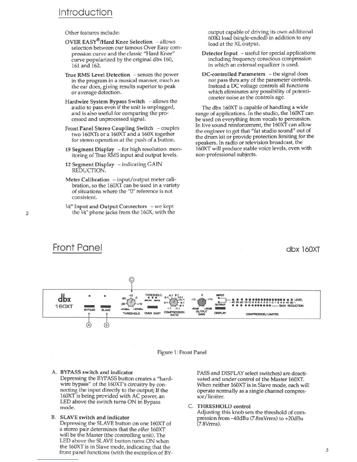
Basic Operation (Control Descriptions)
transfer curve midway between the onset of
processing and that point at which the transfer
curve corresponds to the setting of the RATIO
control (Figure 13.13.). Figure 13. also shows
how the 160XT's THRESHOLD indicator LEDs
correlate with the compression curves.
NOTE: The THRESHOLD setting relates to the
signal level seen by the DETECTOR input. In
normal operation, the program input signal
input is connected directly to the detector
input. If this is not the case, the signal actually
present at the detector input will determine
how ·the 160XTprocesses the signal coming
into its SIGNAL INPUT.
B. COMPRESSION RATIO control:
When an input signal is above the THRESH-
OLD reference level, the setting of this control
determines the number of decibels by which
the input signal must change in level to pro-
duce a ldB increase in the signal level at the
output of the 160XT.A setting of 2:1 indicates
an input:output ratio wherein a 2dB increase in
signal (above threshold) will produce a ldB in-
crease in output signal. A setting of oo:1indi-
cates that an infinite increase in input level
would be required to raise the output level by
ldB.
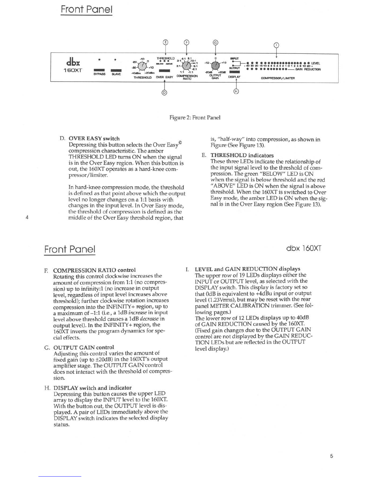
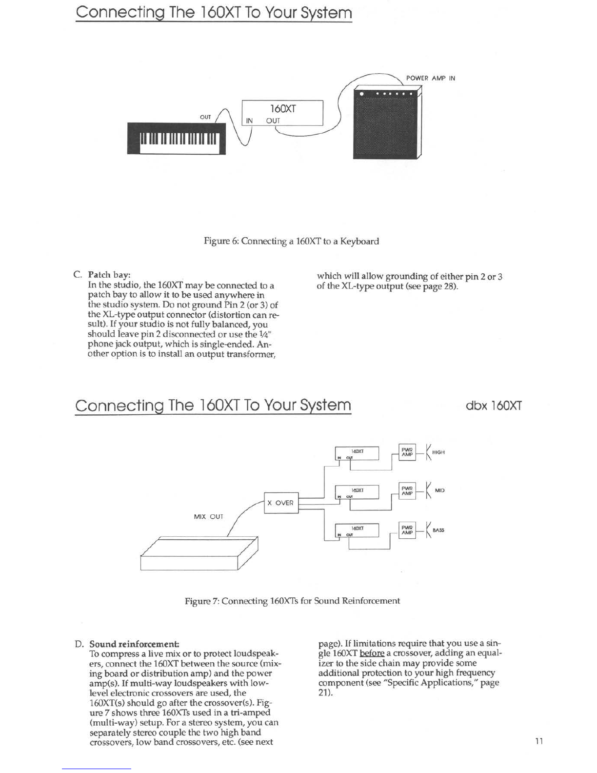
The 160XT's RATIO control covers the entire
range from 1:1 to oo:1and, in addition, goes to
Infinity+ (negative) ratios. At a setting of -1:1,
the above threshold input signal must increase
by ldB in level to decrease the signal at the out-
put of the 160XT by ldB. See Figure 14.
The control curve of the RATIO potentiometer
has been designed to provide total operator
control, with scale expansion at the subtle
lower ratios for easy, repeatable settings.
+20
+15
$
:g,+10
_,
~
+5
5 0
5 -5
0 -10
-15
4 1 6 1
l 1 10 1
·• 1
COMP1ll;SSION
RATIO
\
£--- lhreshold
1:1
4:1
•l:1
-15 -10 -5 0 +5 + 10 +15 +20
INPUTLEVEL(dB)
Figure 14: Ratio Control and Infinity+ (Negative)
Ratios
Basic Operation (Control Descriptions) dbx 160XT
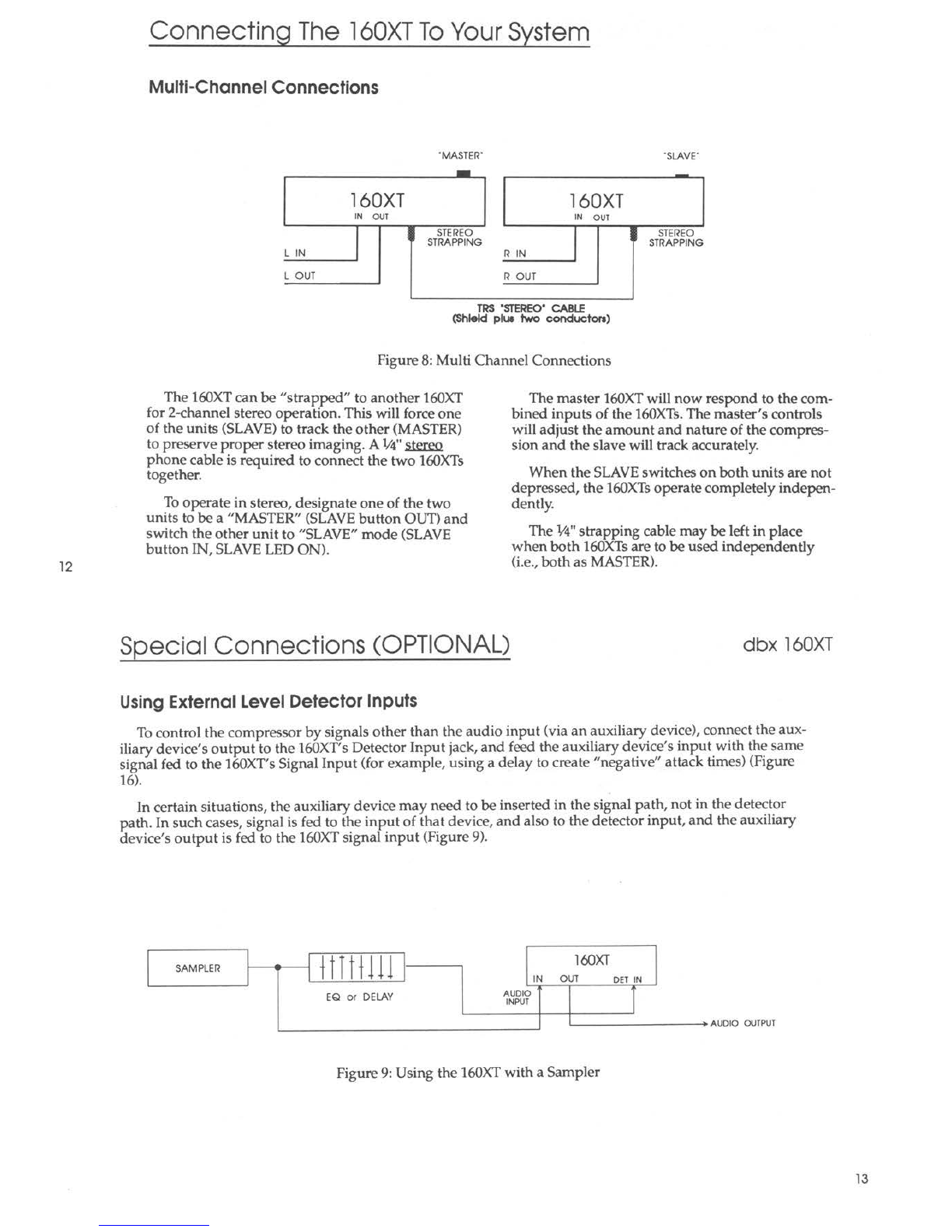
C. SLAVE button (Stereo Operation):
Two channels of program material do not neces-
sarily constitute a stereo program. A stereo pro-
gram is one where the two channels are
recorded and/or mixed to create the illusion of
a single unified "panorama" of sound. The sta-
bility of the psychoacoustic "image" of each
sound source within the stereo program de-
pends upon its ability to maintain a specific
phase and amplitude relationship from left to
right channel.
If two independent compressors are used to
process the stereo pro~ram, a loud _sound o~cur-
ring in one channel will _cau~ea gain ~educhon
only in that channel. This gain reduction would
cause the perceived image of any sound spread
between the two channels to move toward the
side which had not been compressed, because
the spread signal would be mo_mentarily sotter
in the compressed charinel. This can be avoided
by linking the two compressors in such a way
that both channels receiv e the same amount of
compression. On the 160XT,this is acc?m-
plished by means of the STRAPPING ,acks; a
cable between these jacks permits the RMS de-
tectors of both units to "talk" to one another -
but only when one of the u~ts' SLAVE b~ttoi:'s
is depressed. The SLAVE unit then sends its sig-
nal to the MASTER, where the RMS power of
the MASTER and SLAVE signals are combined
to generate a control voltage. This control volt-
age is then used to compress both the MASTER
and SLAVE units equally.
When compressing a stereo program_ with a
pair of 160XTs,only the MASTER urut controls
need to be adjusted.
D. METER CALIBRATION control:
The INPUT /OUTPUT LEVEL DISPLAY in the
160XT is factory-calibrated to indicate "O"when
the signal is +4dBu (1.23Vrms) at eith~r the
input or output of the_160XT,?~pending on the
DISPLAYfunction switch position. (The
METER CALIBRATION control does not affect
the GAIN CHANGE LEDs.)
To recalibrate the LEVEL DISPLAY,depress the
DISPLAYbutton to meter the INPUT LEVEL,
and feed a lkHz signal at the selected nominal
operating level (the level desired for a "OdB"
meter indication) to the 160XT's SIGNAL
INPUT. Then adjust the rear panel METER
CALIBRATION control until the meter indi-
cates "OdB."
17