dbx 12 Series User manual

OPERATION MANUAL
MODE D’EMPLOI
BEDIENUNGSANLEITUNG
MODO DE EMPLEO
®
12 SERIES
EQUALIZER

WARNINGFORYOURPROTECTION
READTHESEINSTRUCTIONS:
KEEPTHESEINSTRUCTIONS
HEEDALLWARNINGS
FOLLOWALLINSTRUCTIONS
DONOTUSETHISAPPARATUSNEARWATER
CLEANONLYWITHADRYCLOTH.
DONOT BLOCKANYOF THEVENTILATION OPENINGS. INSTALL IN ACCORDANCEWITH THEMANU-
FACTURER’SINSTRUCTIONS.
DO NOT INSTALL NEAR ANY HEAT SOURCES SUCH AS RADIATORS, HEAT REGISTERS, STOVES, OR
OTHERAPPARATUS(INCLUDINGAMPLIFIERS)THATPRODUCEHEAT.
ONLYUSEATTACHMENTS/ACCESSORIESSPECIFIEDBYTHEMANUFACTURER.
UNPLUG THIS APPARATUS DURING LIGHTNING STORMS OR WHEN UNUSED FOR LONG PERIODS OF
TIME.
Donot defeatthe safetypurpose ofthepolarized orgrounding-type plug. Apolarized plughas
two blades with one wider than the other. A grounding type plug has two blades and a third
groundingprong. Thewide bladeorthirdprong areprovidedforyour safety. Iftheprovided
plugdoesnotfityouroutlet,consultanelectricianforreplacementoftheobsoleteoutlet.
Protect the power cord from being walked on or pinched particularly at plugs, convenience
receptacles,andthepointwheretheyexitfromtheapparatus.
Use only with the cart stand, tripod bracket, or table specified by the manufacture, or sold
withthe apparatus. Whenacart isused, use cautionwhen movingthecart/apparatus combi-
nationtoavoidinjuryfromtip-over.
Refer all servicing to to qualified service personnel. Servicing is required when the appara-
tus has been damaged in any way, such as power-supply cord or plug is damaged, liquid has
been spilled or objects have fallen into the apparatus, the apparatus has been exposed to rain
ormoisture,doesnotoperatenormally,orhasbeendropped.
POWER ON/OFF SWITCH: For products provided with a power switch, the power switch DOES
NOTbreaktheconnectionfromthemains.
MAINS DISCONNECT: The plug shall remain readily operable. For rack-mount or installation
where plug is not accessible, an all-pole mains switch with a contact separation of at least 3
mmineachpoleshallbeincorporatedintotheelectricalinstallationoftherackorbuilding.
FOR UNITS EQUIPPED WITH EXTERNALLY ACCESSIBLE FUSE RECEPTACLE: Replace fuse with
sametypeandratingonly.
MULTIPLE-INPUTVOLTAGE: Thisequipmentmay requiretheuse ofadifferent linecord,attach-
mentplug,orboth,dependingon the availablepowersourceatinstallation.Connectthisequip-
ment only to the power source indicated on the equipment rear panel. To reduce the risk of
fireorelectricshock,referservicingtoqualifiedservicepersonnelorequivalent.
ThisEquipmentisintendedforrackmountuseonly.
SAFETYINSTRUCTIONS
NOTICEFORCUSTOMERSIFYOURUNITISEQUIPPEDWITHAPOWERCORD.
WARNING:THISAPPLIANCEMUSTBEEARTHED.
Thecoresinthemainsleadarecolouredinaccordancewiththefollowingcode:
GREENandYELLOW-Earth BLUE-Neutral BROWN-Live
As colours of the cores in the mains lead of this appliance may not correspond with the coloured mark-
ingsidentifyingtheterminalsinyourplug,proceedasfollows:
•The core which is coloured green and yellow must be connected to the terminal in the plug
markedwiththeletterE,orwiththeearthsymbol,orcolouredgreen,orgreenandyellow.
•ThecorewhichiscolouredbluemustbeconnectedtotheterminalmarkedNorcolouredblack.
•ThecorewhichiscolouredbrownmustbeconnectedtotheterminalmarkedLorcolouredred.
This equipment may require the use of a different line cord, attachment plug, or both, depending on the
available power source at installation. If the attachment plug needs to be changed, refer servicing to
qualifiedservice personnel whoshouldrefer tothetable below. Thegreen/yellowwireshall beconnect-
eddirectlytotheunitschassis.
WARNING:Ifthe ground isdefeated,certainfault conditions intheunitor in thesystemto which itiscon-
nected can result in full line voltage between chassis and earth ground. Severe injury or death can then
resultifthechassisandearthgroundaretouchedsimultaneously.
LIVE
ENEUTRAL
EARTH GND
CONDUCTOR
L
NBROWN
BLUE
GREEN/YEL
BLACK
Normal Alt
WIRE COLOR
WHITE
GREEN
Thesymbolsshownaboveareinternationallyacceptedsymbolsthatwarn of potential hazards with
electricalproducts. The lightning flashwitharrowpoint in anequilateral triangle means thatthere
are dangerous voltages present within the unit. The exclamation point in an equilateral triangle
indicatesthatitisnecessaryfortheusertorefertotheowner’smanual.
Thesesymbolswarn that there arenouserserviceableparts inside the unit. Donotopentheunit.
Do not attempt to service the unit yourself. Refer all servicing to qualified personnel. Opening the
chassisfor any reasonwillvoid the manufacturer’swarranty. Donot get theunitwet. If liquid is
spilled on the unit, shut it off immediately and take it to a dealer for service. Disconnect the unit
duringstormstopreventdamage.
CAUTION
ATTENTION: RISQUE DE CHOC ELECTRIQUE - NE PAS OUVRIR
WARNING: TO REDUCE THE RISK OF FIRE OR ELECTRIC
SHOCK DO NOT EXPOSE THIS EQUIPMENT TO RAIN OR MOISTURE
RISK OF ELECTRIC SHOCK
DO NOT OPEN
IMPORTANT SAFETY INSTRUCTIONS

U.K. MAINS PLUG WARNING
A molded mains plug that has been cut off from the cord is unsafe.
Discard the mains plug at a suitable disposal facility. NEVER UNDER
ANY CIRCUMSTANCES SHOULD YOU INSERT A DAMAGED OR CUT
MAINS PLUG INTO A 13 AMP POWER SOCKET. Do not use the
mains plug without the fuse cover in place. Replacement fuse cov-
ers can be obtained from your local retailer. Replacement fuses are
13 amps and MUST be ASTA approved to BS1362.
LITHIUM BATTERY
WARNING
CAUTION!
This product may contain a lithium battery. There is danger of
explosion if the battery is incorrectly replaced. Replace only
with an Eveready CR 2032 or equivalent. Make sure the bat-
tery is installed with the correct polarity. Discard used batter-
ies according to manufacturer’s instructions.
ADVARSEL!
Lithiumbatteri - Eksplosjonsfare. Ved utskifting benyttes kun
batteri som anbefalt av apparatfabrikanten. Brukt batteri
returneres apparatleverandøren.
ADVARSEL!
Lithiumbatteri - Eksplosionsfare ved fejlagtig håndtering.
Udskiftning må kun ske med batteri av samme fabrikat og
type. Levér det brugte batteri tilbage til leverandøren.
VAROITUS!
Paristo voi räjähtää, jos se on virheellisesti asennettu. Vaihda
paristo ainoastaan laitevalmistajan suosittelemaan tyyppin.
Hävitä käytetty paristo valmistajan ohjeiden mukaisesti.
VARNING!
Explosionsfara vid felaktigt batteribyte. Använd samma batteri-
typ eller en ekvivalent typ som rekommenderas av apparattil-
lverkaren. Kassera använt batteri enligt fabrikantens instruk-
tion.
IMPORTANT SAFETY INSTRUCTIONS
ELECTROMAGNETIC
COMPATIBILITY
This unit conforms to the Product
Specifications noted on the Declaration of
Conformity. Operation is subject to the fol-
lowing two conditions:
• this device may not cause harmful inter-
ference, and
• this device must accept any interference
received, including interference that may
cause undesired operation.
Operation of this unit within significant elec-
tromagnetic fields should be avoided.
• use only shielded interconnecting cables.
DECLARATION OF
CONFORMITY
Manufacturer’s Name: dbx Professional Products
Manufacturer’s Address: 8760 S. Sandy Parkway
Sandy, Utah 84070, USA
declares that the product:
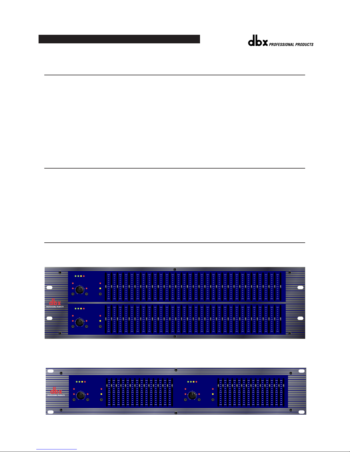
Product name: dbx 1215 and dbx1231
Note: Product name may be suffixed by
the letters-EU.
Product option: None
conforms to the following Product Specifications:
Safety: IEC 60065 (1998)
EMC: EN 55013 (1990)
EN 55020 (1991)
Supplementary Information:
The product herewith complies with the requirements of the Low Voltage
Directive 73/23/EEC and the EMC Directive 89/336/EEC as amended by
Directive 93/68/EEC.
Vice-President of Engineering
8760 S. Sandy Parkway
Sandy, Utah 84070, USA
Date: July 1, 2003
European Contact: Your local dbx Sales and Service Office
or
Harman Music Group
8760 South Sandy Parkway
Sandy, Utah
84070 USA Ph: (801) 566-8800
Fax: (801) 568-7583
WARRANTY
1. The warranty registration card that accompanies this product must be mailed within 30 days after purchase
date to validate this warranty. Proof-of-purchase is considered to be the burden of the consumer.
2. dbx warrants this product, when bought and used solely within the U.S., to be free from defects in materials
and workmanship under normal use and service.
3. dbx liability under this warranty is limited to repairing or, at our discretion, replacing defective materials that
show evidence of defect, provided the product is returned to dbx WITH RETURN AUTHORIZATION from
the factory, where all parts and labor will be covered up to a period of two years. A Return Authorization
number must be obtained from dbx by telephone. The company shall not be liable for any consequential
damage as a result of the product's use in any circuit or assembly.
4. dbx reserves the right to make changes in design or make additions to or improvements upon this product
without incurring any obligation to install the same additions or improvements on products previously manu-
factured.
5. The foregoing is in lieu of all other warranties, expressed or implied, and dbx neither assumes nor autho-
rizes any person to assume on its behalf any obligation or liability in connection with the sale of this product.
In no event shall dbx or its dealers be liable for special or consequential damages or from any delay in the
performance of this warranty due to causes beyond their control.


MANUAL CONTENTS
INTRODUCTION . . . . . . . . . . . . . . . . . . . . . . . . . . . . . . . . . . . . . . . . . . . . . . . . . . 2
INSPECTION . . . . . . . . . . . . . . . . . . . . . . . . . . . . . . . . . . . . . . . . . . . . . . . . . . . . 2
OPERATING CONTROLS . . . . . . . . . . . . . . . . . . . . . . . . . . . . . . . . . . . . . . . . . . . . 2
CONNECTING THE EQ TO YOUR SYSTEM . . . . . . . . . . . . . . . . . . . . . . . . . . . . . . . 3
REAR PANEL DESCRIPTIONS . . . . . . . . . . . . . . . . . . . . . . . . . . . . . . . . . . . . . . . . 4
INSTALLATION CONSIDERATIONS . . . . . . . . . . . . . . . . . . . . . . . . . . . . . . . . . . . . . 5
OPERATION AND APPLICATIONS NOTES . . . . . . . . . . . . . . . . . . . . . . . . . . . . . . . 5
TECHNICAL SUPPORT / FACTORY SERVICE . . . . . . . . . . . . . . . . . . . . . . . . . . . . . . 6
FRANÇAIS . . . . . . . . . . . . . . . . . . . . . . . . . . . . . . . . . . . . . . . . . . . . . . . . . . . . . 7
DEUTSCH . . . . . . . . . . . . . . . . . . . . . . . . . . . . . . . . . . . . . . . . . . . . . . . . . . . . . 17
ESPAÑOL . . . . . . . . . . . . . . . . . . . . . . . . . . . . . . . . . . . . . . . . . . . . . . . . . . . . . 27
SPECIFICATIONS . . . . . . . . . . . . . . . . . . . . . . . . . . . . . . . . . . . . . . . . . . . . . . . . . 37
BLOCK DIAGRAM . . . . . . . . . . . . . . . . . . . . . . . . . . . . . . . . . . . . . . . . . . . . . . . . 39
MANUAL CONTENTS
1
12 SERIES GRAPHIC EQUALIZERS

INTRODUCTION
Congratulations on your purchase of a dbx graphic equalizer. All dbx graphic equalizers are high performance
multi-functional units designed to deliver all the flexibility and power that professional users demand. We recom-
mend that you take a moment to read through this operation manual. It provides information that will assist you
from system set-up to EQ applications. The 12 Series Equalizers include the following features:
• Switchable Boost/Cut range between ±6dB and ±15dB
• Balanced inputs and outputs
• XLR, Barrier Strip, and 1/4" TRS connectors
• -12dB/+12dB input gain range
• 18dB/octave 40Hz Bessel Low-Cut filter
• Chassis/signal ground lift capability
• Internal power supply transformer
• Power-off hard-wire relay bypass with 2-second power-up delay
INSPECTION
Verify that the equalizer’s package contains the following:
• Equalizer unit matching serial number marked on package
• AC power cord
• Operation Manual
• Registration Card
• Four rack mount screws and washers
If any of these items are missing please contact dbx customer service at the number provided on the back cover of
this manual.
OPERATING CONTROLS Front Panels
1231 - dual channel 31 band graphic equalizer
1215 - dual channel 15 band graphic equalizer
2
®
OPERATION MANUAL
1231
Graphic Equalizer
20 25 31.5 40 50 63 80 500400315250 1.6k1.25k1k800 5k4k3.15k2.5k 16k12.5k10k8k6.3k 20k2k630100 125 160 200
RANGE
OUTPUT
LEVEL (dBu)
LOW
CUT
EQ
BYPASS INPUT
GAIN
dB
-12
0
+12
+/-6
+/-15
CLIP
+18+100-10
RANGE
OUTPUT
LEVEL (dBu)
LOW
CUT
EQ
BYPASS INPUT
GAIN
dB
-12
0
+12
+/-6
+/-15
CLIP
+18+100-10
0
-15
+15
0
-15
+15
0
-6
+6
0
-6
+6
RANGE
OUTPUT
LEVEL (dBu)
LOW
CUT
EQ
BYPASS INPUT
GAIN
dB
-12
0
+12
+/-6
+/-15
CLIP
0
-6
+6
25 40 63 100 160 250 400 16k10k6.3k4k630 1k 1.6k 2.5k
+18+100-10
1215
Graphic Equalizer
0
-15
+15
RANGE
OUTPUT
LEVEL (dBu)
LOW
CUT
EQ
BYPASS INPUT
GAIN
dB
-12
0
+12
+/-6
+/-15
CLIP
0
-6
+6
25 40 63 100 160 250 400 16k10k6.3k4k630 1k 1.6k 2.5k
+18+100-10
0
-15
+15

Input Gain Control: This control sets the signal level to the equalizer. It is capable of -12dB to +12dB of gain. Its
effect is apparent by viewing the OUTPUT LEVEL BAR GRAPH.
EQ Bypass: This switch removes the graphic equalizer section from the signal path. (See Block diagram on Page
8.) The BYPASS switch does not, however, affect the INPUT GAIN, or LOW CUT filters.
EQ Bypass LED: This red LED lights when the EQ is in bypass mode. Note that bypass mode only effects the
graphic equalizer section of the 12 Series EQs. The INPUT GAIN and and LOW CUT controls remain unaffected
when the EQ is bypassed.
Boost/Cut Range Selection Switch and LEDs: This switch selects which of the two boost/cut ranges the equalizer
will use, either ±6dB or ±15dB. The red LED lights when the ±15dB range is selected, and the yellow LED lights
when the ±6dB range is selected. Note that the BOOST/CUT switch is slightly recessed. This is to prevent acciden-
tal activation of the switch, possibly causing damage to other sound system components.
Output Level Bar Graph: These four LEDs indicate output level of the equalizer. The red LED is 3dB below clip-
ping and is marked as +18dBu. It monitors the level at the output of the equalizer after all other processing.
Clip LED: This LED lights whenever any internal signal level reaches 3dB below clipping which may occur when
any of the following happen: 1) the input signal is “hotter” than +22dBu, 2) excessive gain is applied by the input
gain control, or 3) excessive boost is applied using the frequency sliders.
Frequency Band Slider Controls: Each one of these slider potentiometers will boost or cut at its noted frequency
by ±6dB or ±15dB, depending upon the position of the BOOST/CUT RANGE switch. When all the sliders are in
the center detented position the output of the equalizer is flat. The frequency band centers of the 1231 are marked at
1/3rd of an octave intervals on ISO standard spacings, while the frequency band centers of the 1215 are marked at
2/3rds of an octave intervals on ISO standard spacings.
Low Cut Enable Switch: The LOW-CUT switch inserts or removes the 18dB/octave 40Hz Bessel low-cut filter
from the signal path. When the LOW-CUT switch is pushed in, the LOW-CUT filter is IN the audio path.
CONNECTING THE EQ TOYOUR SYSTEM
The 12 Series Equalizers have balanced inputs and outputs that can be used with any balanced or unbalanced line-
level device. For more specific information about cabling possibilities, please refer to the section entitled
Installation Considerations, Page 5.
To connect the equalizer to your sound system refer to the following steps:
• Turn off all equipment before making connections.
• Mount equalizer in a standard-width rack.
Install the EQs in a rack with the rack screws provided. It can be mounted above or below anything that does
not generate excessive heat. Ambient temperatures should not exceed 113° F (45°C) when equipment is in use.
Although the unit’s chassis is shielded against radio frequency and electromagnetic interference, extremely
high fields of RF and EMI should be avoided.
• Make audio connections via XLR, barrier strip, or 1/4" TRS jacks (according to application needs)
All three types of connectors for the inputs and outputs can be used for balanced or unbalanced connections.
The use of more than one connector at a time for the inputs could unbalance balanced lines, cause phase cancel-
lation, short a conductor to ground, or cause damage to other equipment connected to the equalizer. More than
one output may be used simultaneously as long as the combined parallel load is greater than 600Ω.
• Select the operating range with the BOOST/CUT RANGE SELECTION switch
Note: Be sure to reduce audio levels at the power amplifiers when changing the setting of this switch as it may generate an audible transient.
• Apply power to the equalizer
Connect the AC power cord to the AC power receptacle on the back of the equalizer. Route the AC power cord
to a convenient power outlet away from audio lines. The unit may be turned on and off from the rear panel
OPERATION MANUAL
3
12 SERIES GRAPHIC EQUALIZERS

power switch or a master equipment power switch. Since the 12 Series Equalizers consume a relatively small
amount of power, the units may be left on continuously.
REAR PANEL DESCRIPTIONS Rear Panels
1231 - dual channel 31 band graphic equalizer
1215 - dual channel 15 band graphic equalizer
Power Switch: Switches the power on and off. Always make audio connections with the power switch in the OFF
position.
Power Cord Receptacle: Connects AC power to the equalizer.
Output Connectors: Three types of output connectors are provided for output connections: male XLR type con-
nectors, 1/4" tip-ring-sleeve phone jack connectors and a barrier strip.
Input Connectors: Three types of input connectors are provided for input connections: female locking XLR type
connectors, 1/4" tip-ring-sleeve phone jack connectors, and a barrier strip. The maximum input level that the equal-
izer can accept is +22dBu (ref: 0.775Vrms).
Chassis Ground Lift Strap: By removing the jumper connecting the two screws on the barrier strip, the chassis
ground is separated from the circuit ground of the equalizer. This is sometimes necessary to prevent “ground loops”
in a sound system. When lifting the ground strap, you must make a connection from the circuit ground ( ) terminal
to some other ground point in your audio system in order for the equalizer to function properly.
4
®
OPERATION MANUAL
24 WATTS
OUTPUT INPUT
PHONE:
TIP
RING
SLEEVE
XLR:
PIN 1
PIN 2
PIN 3
CONNECTOR POLARITY
INPUTOUTPUT
OUTPUT INPUT
INPUTOUTPUT
100V 50/60Hz
120V 60Hz
PROFESSIONAL PRODUCTS
A HARMAN INTERNATIONAL
COMPANY
MODEL 1231
EQUALIZER
WARNING:
TO REDUCE THE RISK OF FIRE OR ELECTRIC
SHOCK DO NOT EXPOSE THIS EQUIPMENT TO RAIN OR MOISTURE
RISK OF ELECTRIC SHOCK
DO NOT OPEN
ATTENTION:
RISQUE DE CHOC ELECTRIQUE - NE PAS OUVRIR
CAUTION:
TO REDUCE
THE RISK OF FIRE REPLACE
ONLY WITH SAME TYPE FUSE.
ATTENTION:
UTILISER
UN FUSIBLE DE RECHANGE DE
MEME TYPE.
POWER
MANUFACTURED UNDER ONE OR MORE OF THE FOLLOWING
U.S. PATENTS: 4,234,804 4,316,107 4,329,598 4,331,931 4,377,792
4,403,199 4,409,500 4,425,551 4,434,380 4,454,433 4,471,324
4,473,793 OTHER PATENTS PENDING
OUTPUT
-
+INPUT
-
+
OUTPUT
-
+INPUT
-
+
OUTPUT
-
+INPUT
-
+
OUTPUT INPUT
PHONE:
TIP
RING
SLEEVE
XLR:
PIN 1
PIN 2
PIN 3
CONNECTOR POLARITY
INPUTOUTPUT
OUTPUT
-
+INPUT
-
+
OUTPUT INPUT
INPUTOUTPUT
PROFESSIONAL PRODUCTS
A HARMAN INTERNATIONAL
COMPANY
MODEL 1215
EQUALIZER MANUFACTURED UNDER ONE OR MORE OF THE FOLLOWING
U.S. PATENTS: 4,234,804 4,316,107 4,329,598 4,331,931 4,403,199
4,409,500 4,425,551 4,434,380 4,454,433 4,471,324 4,473,793
OTHER PATENTS PENDING
WARNING:
TOREDUCETHERISKOFFIREORELECTRIC
SHOCKDONOTEXPOSETHISEQUIPMENTTORAINORMOISTURE
RISKOFELECTRICSHOCK
DONOTOPEN
ATTENTION:
RISQUEDECHOCELECTRIQUE-NEPASOUVRIR
CAUTION:
TOREDUCE
THERISKOFFIREREPLACE
ONLYWITHSAMETYPEFUSE.
ATTENTION:
UTILISER
UNFUSIBLEDERECHANGEDE
MEMETYPE.
24 WATTS
POWER
100V 50/60Hz
120V 60Hz

INSTALLATION CONSIDERATIONS
Hookups and Cabling: The 12 Series Equalizers are designed for nominal +4dBu levels. The equalizers can be
used with either balanced or unbalanced sources, and the outputs can be used with either balanced or unbalanced
loads, provided the proper cabling is used.
A balanced line is defined as two-conductor shielded cable with the two center conductors carrying the same signal
but of opposite polarity when referenced to ground. An unbalanced line is generally a single-conductor shielded
cable with the center conductor carrying the signal and the shield at ground potential.
Input Cable Configurations: The equalizer has an input impedance of 40kΩbalanced and 20kΩunbalanced. This
makes the 12 Series Equalizers’ audio inputs suitable for use with virtually any low source impedance (under 2kΩ).
Output Cable Configurations: The equalizer’s output is capable of driving a 600Ωload to +18dBu. For maximum
hum rejection with a balanced source, avoid common grounding at the equalizer’s inputs and outputs. Most bal-
anced (3-conductor) cables have the shield connected at both ends. This can result in ground loops which cause
hum. If hum persists try disconnecting the shield on one or more of the cables in the system, preferably at the input
of a device, not at the output.
OPERATION AND APPLICATION NOTES
The dbx 12 Series Graphic Equalizers are useful audio signal processing tools in situations where precise frequency
control is required across the audible frequency spectrum.
When used with an audio spectrum analyzer the EQs can tune any acoustical environment -- from the studio to the
concert hall -- to stop ringing, increase clarity, and flatten the overall frequency response of the environment. A
real-time spectrum analyzer or other types of audio environment analyzers are very useful in determining the
amount of equalization needed.
Insert the graphic equalizer between the signal source (usually a mixer) and the power amplifiers (or the crossover if
there is one). Adjust the level and equalization as required to yield the desired system response. The long throw
faders of the EQs allow very precise settings of the equalization for accurate equalization curves.
For optimum signal-to-noise response, the gain structure of the sound system must be properly set up. Each compo-
nent of the sound system should be set at its nominal operating level, starting with the first element in the system,
usually a mixing console. Each element should be run at its nominal operating level in order to take advantage of
the maximum signal-to-noise properties of that element. Loudspeaker amplifiers, as the last element in the chain,
should be set only as loud as necessary, in order to avoid inducing unnecessary noise into the system.
++
+
++ +
++
Without Jumper in Place With Jumper in Place
jumper
optional
circuit
ground chassis
ground
circuit
ground chassis
ground
to system
ground
optional Input
Cable
Output
Cable
Input
Cable
Output
Cable
Wiring Connections With Ground
OPERATION MANUAL
5
12 SERIES GRAPHIC EQUALIZERS

TECHNICAL SUPPORT / FACTORY SERVICE
The dbx 12 Series EQs are all solid-state products with components chosen for high performance and excellent reli-
ability. Each unit has been tested and burned-in at the factory. No adjustment of any type should be required
throughout the life of the unit.
If circumstances arise which necessitate repair, we recommend that your EQ be returned to the factory. This can
only be done by receiving a RETURN AUTHORIZATION number from dbx customer service.
If you require technical support contact Customer Service. Be prepared to accurately describe the problem. Know
the serial number of your unit (printed on a sticker attached to the chassis of the unit).
Contact information is printed on the back cover of this manual.
6
®
OPERATION MANUAL

MODE D’EMPLOI
7
CORRECTEURS GRAPHIQUES SÉRIES 12
FRANÇAIS

ATTENTION
VEUILLEZ LIRE CE QUI SUIT :
CONSERVEZ CES INSTRUCTIONS
RESPECTEZ TOUTES LES CONSIGNES
SUIVEZ TOUTES LES INSTRUCTIONS
NETTOYEZ L’APPAREIL UNIQUEMENT AVEC UN LINGE HUMIDE.
NE BLOQUEZ PAS LES OUÎES DE VENTILATION. RESPECTEZ LES
CONSIGNES D’INSTALLATION DU FABRICANT.
N’INSTALLEZ PAS L’APPAREIL À PROXIMITÉ DE SOURCES DE
CHALEUR COMME DES RADIATEURS OU D D’AUTRES APPAREILS
SUSCEPTIBLES DE PRODUIRE DE LA CHALEUR (Y COMPRIS LES
AMPLIFICATEURS).
UTILISEZ UNIQUEMENT LES APPAREILS OPTIONNELS/ACCES-
SOIRES RECOMMANDÉS PAR LE FABRICANT.
DÉBRANCHEZ CET APPAREIL DURANT LES ORAGES OU LORSQUE
VOUS NE L’UTILISEZ PAS PENDANT DE LONGUES PÉRIODES.
EAU ET HUMIDITÉ : L’appareil ne doit pas être utilisé à proximité de
liquides ou dans un endroit humide (salle de bain, sous-sol humide,
près d’une piscine, etc.). Veillez à ce qu’aucun objet ou liquide ne
pénètre dans l’appareil.
ALIMENTATION : L’appareil doit impérativement être connecté à un
réseau secteur de la tension correspondant à celle inscrite dans le
mode d’emploi ou sur l’appareil.
MISE À LA TERRE OU POLARISATION : Véillez à ne pas modifier la
mise à la terre ou la polarisation de l’appareil.
PROTECTION DU CORDON SECTEUR : Les cordons d’alimentation
doivent être placés de sorte qu’il soit impossible de marcher dessus.
Vérifiez que les cordons ne sont pas pincés ou écrasés par des
objets placés dessus ou à côté. Veillez au bon dégagement du cor-
don sur la prise secteur murale (ou multiprise) et sur l’appareil.
MAINTENANCE : Pour réduire les risques d’incendie et d’électrocu-
tion, l’utilisateur doit uniquement effectuer sur l’appareil les opéra-
tions indiquées dans le mode d’emploi. Les opérations de mainte-
nance doivent être confiées à des personnes qualifiées.
POUR LES APPAREILS ÉQUIPÉS D’UN FUSIBLE ACCESSIBLE :
Remplacez le fusible uniquement par un fusible du même type et du
même calibre.
TENSION D’ENTRÉE MULTIPLE : Cet appareil peut nécessiter un
cordon et/ou une prise différents, selon l’alimentation disponible à
l’installation. Connectez uniquement cet appareil au type d’laimenta-
tion indiqué en face arrière de l’appareil. Pour réduire le risque
d’électrocution, confiez la maintenance à des personnes qualifiées.
CONSIGNES DE SÉCURITÉ
APPAREILS POURVUS D’UN CORDON SECTEUR.
ATTENTION : CET APPAREIL DOIT ÊTRE RELIÉ À LA TERRE.
Les câbles du cordon secteur sont repérés par couleurs :
VERT et JAUNE - Terre BLEU - Neutre MARRON - Phase
Les couleurs utilisées par le cordon secteur de cet appareil peuvent être dif-
férentes de celles utilisées par votre embase secteur :
• Le câble couleur verte et jaune doit être connecté au plot vert et jaune ou
repéré par la lettre E (ou le symbole de la Terre).
• Le câble bleu doit être raccordé au plot N ou noir de l’embase.
• Le câble marron doit être connecté au plot au plot L ou rouge de l’embase
secteur.
Cet appareil peut nécessiter l’utilisation d’un type différent de cordon secteur,
d’une liaison différente, voire les deux, selon la source utilisée lors de l’installa-
tion. Si vous devez modifier la fiche, consultez un personnel qualifié (code des
couleurs indiqué dans le tableau ci-dessous). Le câble jaune/vert doit être
directement relié au châssis de l’appareil.
ATTENTION : En cas de découplage de la terre, l’apparel peut présenter ou
causer des dysfonctionnements pouvant entraîner des accidents graves ou mor-
tels lors de contacts entre le châssis et la terre.
LIVE
ENEUTRAL
EARTH GND
CONDUCTOR
L
NBROWN
BLUE
GREEN/YEL
BLACK
Normal Alt
WIRE COLOR
WHITE
GREEN
Les symboles internationaux illustrés ci-dessus signalent un danger élec-
trique potentiel. L’éclair indique la présence de tensions dangereuses dans
l’appareil. Le point d’exclamation indique à l’utilisateur la nécessité de con-
sulter le mode d’emploi.
Ces symboles vous indiquent que l’appareil ne contient aucune pièce sus-
ceptible d’être remplacée par l’utilisateur. Ne pas ouvrir l’appareil.
N’essayez pas de réparer l’appareil vous-mêmes. Consultez des personnes
qualifiées. L’ouverture du boîtier de l’appareil pour quelque raison que ce
soit entraîne instantanément la garantie constructeur. Ne mettez jamais
l’appareil en contact avec des liquides. Si du liquide est renversé sur
l’appareil, mettez-le immédiatement hors tension et confiez-le à un service
de maintenance compétent ou à votre revendeur. En cas d’orage, décon-
nectez l’appareil du secteur.
CAUTION
ATTENTION: RISQUE DE CHOC ELECTRIQUE - NE PAS OUVRIR
WARNING: TO REDUCE THE RISK OF FIRE OR ELECTRIC
SHOCK DO NOT EXPOSE THIS EQUIPMENT TO RAIN OR MOISTURE
RISK OF ELECTRIC SHOCK
DO NOT OPEN
CONSIGNES DE SÉCURITÉ IMPORTANTES

U.K. MAINS PLUG WARNING
A molded mains plug that has been cut off from the cord is unsafe. Discard the mains plug at a suitable disposal
facility. NEVER UNDER ANY CIRCUMSTANCES SHOULD YOU INSERT A DAMAGED OR CUT MAINS PLUG INTO A 13
AMP POWER SOCKET. Do not use the mains plug without the fuse cover in place. Replacement fuse covers can be
obtained from your local retailer. Replacement fuses are 13 amps and MUST be ASTA approved to BS1362.
CONSIGNES DE SÉCURITÉ IMPORTANTES
COMPATIBILITÉ
ÉLECTROMAGNÉTIQUE
Cet appareil est conforme aux carac-
téristiques portée sur la déclaration de
conformité (ci-contre). L’utilisation
est soumise aux conditions suivantes :
•Cet appareil ne doit causer
aucune interférence dangereuse.
• Cet appareil doit accepter toutes
les interférences reçues, y com-
pris celles susceptibles d’engen-
drer un dysfonctionnement.
Évitez d’utiliser cet appareil dans une
zone soumise à d’importants champs
électromagnétiques.
• Utilisez uniquement des câbles
blindés.
DÉCLARATION DE
CONFORMITÉ
Nom du fabricant : dbx Professional Products
Adresse du fabricant : 8760 S. Sandy Parkway
Sandy, Utah 84070, USA
Déclare que le produit :
Nom du produit : dbx 1231, dbx 1215
Option du produit : Non communiquée
est conforme aux caractéristiques suivantes :
Sécurité : IEC 60065 (1998)
EMC : EN 55013 (1990)
EN 55020 (1991)
Informations supplémentaires :
Ce produit est conforme aux exigences de la
norme de basse tension (Low Voltage Directive)
73/23/EEC et de la norme EMC 89/336/EEC telle
qu’amendée par la norme 93/68/EEC.
dbx Professional Products
Vice-Président du service technique
8760 S. Sandy Parkway
Sandy, Utah 84070, USA
July 1, 2003
Contact européen : Votre revendeur local dbx ou
Harman Music Group
8760 South Sandy Parkway
Sandy, Utah
84070 USA
(801) 568-7638
(801) 568-7642


TABLE DES MATIÈRES
INTRODUCTION . . . . . . . . . . . . . . . . . . . . . . . . . . . . . . . . . . . . . . . . . . . . . . . . . . 12
INSPECTION . . . . . . . . . . . . . . . . . . . . . . . . . . . . . . . . . . . . . . . . . . . . . . . . . . . . 12
RÉGLAGES . . . . . . . . . . . . . . . . . . . . . . . . . . . . . . . . . . . . . . . . . . . . . . . . . . . . . 12
CONNEXION DU CORRECTEUR À VOTRE SYSTEME . . . . . . . . . . . . . . . . . . . . . . . . 13
DESCRIPTION DES FACES ARRIERES . . . . . . . . . . . . . . . . . . . . . . . . . . . . . . . . . . . 14
INSTALLATION . . . . . . . . . . . . . . . . . . . . . . . . . . . . . . . . . . . . . . . . . . . . . . . . . . 15
NOTES SUR L’UTILISATION ET LES APPLICATIONS . . . . . . . . . . . . . . . . . . . . . . . . 15
ASSISTANCE TECHNIQUE / SERVICE . . . . . . . . . . . . . . . . . . . . . . . . . . . . . . . . . . . 16
TAB:E DES MATIERES
11
CORRECTEURS GRAPHIQUES SÉRIES 12

INTRODUCTION
Nous vous remercions de la confiance que vous nous témoignez en choisissant un correcteur graphique dbx. Tous
les correcteurs graphiques dbx sont des appareils multifonctionnels de haute qualité, conçus pour délivrer toute la
souplesse et la puissance nécessaires à une utilisation professionnelle. Nous vous recommandons de prendre le
temps de lire ce mode d’emploi. Il vous fournit toutes les informations nécessaires, de l’installation du système aux
applications d’égalisation. Les correcteurs série 12 offrent les fonctions suivantes :
• Plage d’atténuation/accentuation commutable entre ±6 dB et ±15 dB
• Entrées et sorties symétriques
• Connecteurs XLR, sur bornier et Jack stéréo 6,35 mm
• Plage de gain d’entrée -12 dB/+12 dB
• Filtre passe-haut 18 dB/octave 40 Hz de type Bessel
• Fonction de découplage de masse
• Transformateur interne d’alimentation
• Fonction de Bypass par relai (mise hors tension) avec délai de 2 secondes à la mise sous tension.
INSPECTION
Vérifiez que le pack du correcteur contient les éléments suivants :
• Appareil dont le numéro de série correspond à celui indiqué sur l’emballage
• Cordon d’alimentation
• Mode d’emploi
• Carte d’enregistrement
• Quatre vis et rondelles de montage en rack
Si l’un de ces éléments manque, veuillez contacter le service clientèle dbx au numéro indiqué au dos de ce mode
d’emploi.
RÉGLAGES Faces avant
1231 - Correcteur graphique 31 bandes deux canaux
1215 - Correcteur graphique 15 bandes deux canaux
12
®
MODE D’EMPLOI
1231
Graphic Equalizer
20 25 31.5 40 50 63 80 500400315250 1.6k1.25k1k800 5k4k3.15k2.5k 16k12.5k10k8k6.3k 20k2k630100 125 160 200
RANGE
OUTPUT
LEVEL (dBu)
LOW
CUT
EQ
BYPASS INPUT
GAIN
dB
-12
0
+12
+/-6
+/-15
CLIP
+18+100-10
RANGE
OUTPUT
LEVEL (dBu)
LOW
CUT
EQ
BYPASS INPUT
GAIN
dB
-12
0
+12
+/-6
+/-15
CLIP
+18+100-10
0
-15
+15
0
-15
+15
0
-6
+6
0
-6
+6
RANGE
OUTPUT
LEVEL (dBu)
LOW
CUT
EQ
BYPASS INPUT
GAIN
dB
-12
0
+12
+/-6
+/-15
CLIP
0
-6
+6
25 40 63 100 160 250 400 16k10k6.3k4k630 1k 1.6k 2.5k
+18+100-10
1215
Graphic Equalizer
0
-15
+15
RANGE
OUTPUT
LEVEL (dBu)
LOW
CUT
EQ
BYPASS INPUT
GAIN
dB
-12
0
+12
+/-6
+/-15
CLIP
0
-6
+6
25 40 63 100 160 250 400 16k10k6.3k4k630 1k 1.6k 2.5k
+18+100-10
0
-15
+15

Potentiomètre Input Gain : Ce réglage détermine le niveau du signal en entrée du correcteur. Sa plage de réglage
est de -12 dB à +12 dB. Vous pouvez visualiser son effet sur le Bargraph OUTPUT LEVEL.
Touche EQ Bypass : Cette touche permet de couper la section de correction du trajet du signal (voir Synoptique en
page 8). La touche BYPASS n’affecte aucunement le réglage INPUT GAIN ou les filtres passe-haut LOW CUT.
Led EQ Bypass : Cette LED rouge s’allume lorsque le correcteur est en mode Bypass. Notez que le mode Bypass
affecte uniquement la section de correction des correcteurs séries 12. Les réglages INPUT GAIN et LOW CUT ne
sont pas modifiés lorsque le correcteur est bypassé.
Touches et Leds de sélection de la plage d’accentuation/atténuation (RANGE) : Cette touche permet de sélec-
tionner la plage d’accentuation/atténuation utilisée par le correcteur : ±6 dB ou ±15 dB. La Led rouge s’allume
lorsque la plage de ±15 dB est sélectionnée. La Led jaune s’allume lorsque la plage de ±6 dB est sélectionnée.
Notez que la touche d’accentuation/atténuation est légèrement enfoncée afin d’éviter toute activation accidentelle
susceptible d’endommager les autres éléments du système.
Bargraph Output Level : Ces quatres Leds indiquent le niveau de sortie du correcteur. La Led rouge est à 3 dB
avant l’écrêtage et porte la valeur +18 dBu. Elle permet de contrôler le niveau en sortie du correcteur, après tous les
autres traitements.
Led Clip : Cette Led s’allume lorsqu’un signal interne atteint un niveau de 3 dB avant écrêtage, ce qui se produit
lorsque : 1) le niveau du signal d’entrée est plus élevé que +22 dBu, 2) un niveau excessif est appliqué au réglage du
gain d’entrée, ou 3) une accentuation excessive est appliquée à l’aide des curseurs de fréquences.
Curseurs des bandes de fréquences : Chacun de ces curseurs accentue ou atténue la fréquence qui lui est affectée
dans une plage de ±6 dB ou ±15 dB, selon la position de la touche RANGE d’accentuation/atténuation. Lorsque
tous les curseurs sont en position crantée centrale, la sortie du correcteur est plate. Les centres des bandes de
fréquences du 1231 sont espacées par des intervalles standards d’un tiers d’octave (norme ISO), alors que les cen-
tres des bandes de fréquence du 1215 sont espacés par des intervalles de deux tiers d’octave standards (norme ISO).
Touche Low Cut : La touche LOW-CUT insère ou retire du trajet du signal le filtre passe-haut de
18 dB/octave 40 Hz de type Bessel. Quand elle est enfoncée, le filtre passe-haut est inséré dans le trajet du signal.
CONNEXION DU CORRECTEUR À VOTRE SYSTEME
Les correcteurs séries 12 sont équipés d’entrées et de sorties symétriques pouvant être utilisées avec tout appareil à
niveau ligne symétrique ou asymétrique. Pour obtenir des informations plus spécifiques sur les possibilités de
câblage, veuillez vous reporter à la section intitulée Installation, en page 5.
Pour connecter le correcteur à votre système, consultez les instructions :
• Placez tous les appareils hors tension avant d’effectuer les connexions.
• Montez le correcteur dans un rack de largeur standard.
Installez le correcteur dans un rack à l’aide des vis spéciales fournies. Il ne doit pas être monté sur ou sous un
appareil générant une chaleur excessive. La température ambiante ne doit pas excéder 45° C lorsque vous
utilisez l’appareil. Bien que le châssis de l’appareil soit blindé contre les HF et les interférences magnétiques,
vous devez éviter les champs trop importants de HF ou d’interférences électromagnétiques.
• Pour les connexions audio, utilisez les connecteurs XLR, sur bornier ou Jack stéréo (selon applications).
Les 3 types de connecteurs des entrées/sorties permettent des connexions symétriques ou asymétriques. L’utili-
sation de plus d’un connecteur à la fois pour les entrées peut asymétriser les lignes symétriques, causer des
annulations de phase, des court-circuits, ou endommager les appareils reliés au correcteur. Vous pouvez utiliser
plusieurs sorties simultanément tant que la charge totale à supérieure à 600 Ω.
• Sélectionnez la plage d’accentuation/atténuation à l’aide de la touche RANGE.
Note: Réduisez les niveaux audio des amplis de puissance pour modifier le réglage de cette touche afin d’éviter de générer des transitoires audi-
bles.
• Activez le correcteur.
Connectez le cordon d’alimentation à l’embase secteur en face arrière du correcteur. Branchez le cordon d’ali-
MODE D’EMPLOI
13
CORRECTEURS GRAPHIQUES SÉRIES 12

mentation à une prise adéquate, éloignée des lignes audio. L’appareil peut être activé/désactivé à l’aide de l’inter-
rupteur secteur de la face arrière ou de linterrupteur de la prise secteur. Comme les correcteurs des séries 12 con-
somment relativement peu, vous pouvez les laisser continuellement sous tension.
DESCRIPTION DES FACES ARRIERES Faces arrières
1231 - Correcteur graphique 31 bandes deux canaux
1215 - Correcteur graphique 15 bandes deux canaux
Interrupteur Power : Permet de mettre l’appareil sous tension ou hors tension. Effectuez toujours les connexions
lorsque l’appareil est hors tension (position OFF).
Embase secteur : Permet de relier l’appareil au secteur.
Connecteurs Output : L’appareil est équipé de trois types de connecteurs de sortie ; type XLR mâle, Jack stéréo
6,35 mm et sur bornier.
Connecteurs Input : L’appareil est équipé de trois types de connecteurs d’entrée : type XLR femelle à verrouil-
lage, Jack stéréo 6,35 mm et sur bornier. Le niveau d’entrée maximum que peut accepter le correcteur est de +22
dBu (réf. : 0,775 V eff.).
Découplage de masse : En retirant le fil cavalier qui relie les deux vis du bornier, la masse mécanique est décou-
plée de la masse électrique du correcteur. Cela s’avère parfois nécessaire pour éviter les boucles de masse dans un
système sonore. Lorsque vous retirez le fil de masse, vous devez connecter la borne de masse électrique
( ) à un autre point de masse de votre système audio pour que le correcteur fonctionne correctement.
14
®
MODE D’EMPLOI
24 WATTS
OUTPUT INPUT
PHONE:
TIP
RING
SLEEVE
XLR:
PIN 1
PIN 2
PIN 3
CONNECTOR POLARITY
INPUTOUTPUT
OUTPUT INPUT
INPUTOUTPUT
100V 50/60Hz
120V 60Hz
PROFESSIONAL PRODUCTS
A HARMAN INTERNATIONAL
COMPANY
MODEL 1231
EQUALIZER
WARNING:
TO REDUCE THE RISK OF FIRE OR ELECTRIC
SHOCK DO NOT EXPOSE THIS EQUIPMENT TO RAIN OR MOISTURE
RISK OF ELECTRIC SHOCK
DO NOT OPEN
ATTENTION:
RISQUE DE CHOC ELECTRIQUE - NE PAS OUVRIR
CAUTION:
TO REDUCE
THE RISK OF FIRE REPLACE
ONLY WITH SAME TYPE FUSE.
ATTENTION:
UTILISER
UN FUSIBLE DE RECHANGE DE
MEME TYPE.
POWER
MANUFACTURED UNDER ONE OR MORE OF THE FOLLOWING
U.S. PATENTS: 4,234,804 4,316,107 4,329,598 4,331,931 4,377,792
4,403,199 4,409,500 4,425,551 4,434,380 4,454,433 4,471,324
4,473,793 OTHER PATENTS PENDING
OUTPUT
-
+INPUT
-
+
OUTPUT
-
+INPUT
-
+
OUTPUT
-
+INPUT
-
+
OUTPUT INPUT
PHONE:
TIP
RING
SLEEVE
XLR:
PIN 1
PIN 2
PIN 3
CONNECTOR POLARITY
INPUTOUTPUT
OUTPUT
-
+INPUT
-
+
OUTPUT INPUT
INPUTOUTPUT
PROFESSIONAL PRODUCTS
A HARMAN INTERNATIONAL
COMPANY
MODEL 1215
EQUALIZER MANUFACTURED UNDER ONE OR MORE OF THE FOLLOWING
U.S. PATENTS: 4,234,804 4,316,107 4,329,598 4,331,931 4,403,199
4,409,500 4,425,551 4,434,380 4,454,433 4,471,324 4,473,793
OTHER PATENTS PENDING
WARNING:
TOREDUCETHERISKOFFIREORELECTRIC
SHOCKDONOTEXPOSETHISEQUIPMENTTORAINORMOISTURE
RISKOFELECTRICSHOCK
DONOTOPEN
ATTENTION:
RISQUEDECHOCELECTRIQUE-NEPASOUVRIR
CAUTION:
TOREDUCE
THERISKOFFIREREPLACE
ONLYWITHSAMETYPEFUSE.
ATTENTION:
UTILISER
UNFUSIBLEDERECHANGEDE
MEMETYPE.
24 WATTS
POWER
100V 50/60Hz
120V 60Hz

INSTALLATION
Câblages et connexions : Les correcteurs séries 12 sont conçus pour des niveaux nominaux +4 dBu. Les cor-
recteurs peuvent être utilisés avec des sources symétriques ou asymétriques et les sorties peuvent être utilisées avec
des charges symétriques ou asymétriques avec un câblage adéquat.
Une ligne symétrique est véhiculée par comme un câble blindé deux conducteurs dont les deux conducteurs cen-
traux transportent le même signal mais de polarité opposée lorsqu’ils sont référencés à la masse. Une ligne
asymétrique est généralement véhiculée par un câble blindé simple conducteur, dont le conducteur central trans-
porte le signal et le blindage at ground potential.
Configurations des câbles d’entrée : Le correcteur présente une impédance d’entrée de 40 kΩsymétrique et
20 kΩasymétrique. Les entrées audio des correcteurs séries 12 sont donc adaptées à pratiquement toutes les sources
basse impédance (sous 2 kΩ).
Configurations des câbles de sortie : La sortie du correcteur est capable de gérer une charge de 600 Ωà +18 dBu.
Pour un rejet maximum du ronflement avec une source symétrique, évitez de référencer les entrées et les sorties du
correcteur à la même masse. Le blindage de la plupart des câbles symétriques (3 conducteurs) est connecté aux deux
extrémités. Cela peut entraîner des boucles de masse et donc du ronflement. Si le ronflement persiste, essayez de
déconnecter le blindage d’un ou de plusieurs câbles, de préférence à l’entrée d’un appareil (non à la sortie).
NOTES SUR L’UTILISATION ET LES APPLICATIONS
Les correcteurs graphique des séries 12 sont des outils très pratiques dans le traitement des signaux audio : ils per-
mettent un contrôle précis des fréquences sur le spectre audible.
Lorsqu’ils sont utilisés avec un analyseur de spectre audio, les correcteurs sont susceptibles d’accorder n’importe
quel environnement acoustique (du studio à la salle de concert) - ils peuvent atténuer la résonance, augmenter la
clarté et homogénéiser la bande passante globale de l’environnement. L’utilisation d’un analyseur de spectre en
temps réel ou d’autres types d’analyseurs d’envionnement audio est très pratique pour déterminer la quantité de cor-
rection nécessaire.
Insérez le correcteur graphique entre la source sonore (généralement une console de mixage) et les amplis de puis-
sance (ou le filtre actif, s’il y en a un). Déterminez le niveau et la correction nécessaires à la réponse souhaitée. Les
Faders à longue course des correcteurs permettent des réglages très efficaces pour des courbes d’égalisation précis-
es.
Pour obtenir un rapport signal/bruit optimum, la structure de gain du système doit être correctement configurée.
Chaque élément du système sonore doit être réglé à son niveau d’utilisation nominal (dès le premier élément du sys-
tème, qui est généralement une console de mixage). Chaque élément doit être utilisé à son niveau de fonction-
nement nominal afin d’obtenir son meilleur rapport signal/bruit. Les amplificateurs, derniers éléments de la chaîne
doivent être réglés à un niveau optimal, pour ne pas induire de bruit indésirable.
++
+
++ +
++
Without Jumper in Place With Jumper in Place
jumper
optional
circuit
ground chassis
ground
circuit
ground chassis
ground
to system
ground
optional Input
Cable
Output
Cable
Input
Cable
Output
Cable
Connexions à la masse
MODE D’EMPLOI
15
CORRECTEURS GRAPHIQUES SÉRIES 12

ASSISTANCE TECHNIQUE / SERVICE
Les correcteurs séries 12 dbx sont tous des appareils à transistors avec des composants spécialement sélectionnés
pour leur excellente qualité et leur fiabilité. Chaque appareil a été mis sous tension, testé et réglé en usine, et ne
devrait donc nécessiter aucun réglage interne durant toute sa durée de vie.
Si une réparation s’avérait nécessaire, nous vous recommandons de renvoyer l’appareil à l’usine. Vous devez préal-
ablement avoir demandé votre numéro d’autorisation de retour (RETURN AUTHORIZATION) au service clientèle
de dbx.
Lorsque vous contactez les services de maintenance, préparez-vous à décrire le problème de manière précise et à
donner le numéro de série de votre appareil (imprimé sur un autocollant placé sous l’appareil).
Les informations concernant les services sont imprimées au dos de ce mode d’emploi.
16
®
MODE D’EMPLOI
Other manuals for 12 Series
2
This manual suits for next models
2
Table of contents
Languages:
Other dbx Stereo Equalizer manuals

dbx
dbx 1215 User manual

dbx
dbx 1231 User manual

dbx
dbx 131, 215, 231 User manual

dbx
dbx DriveRack 442 User manual

dbx
dbx DriveRack 4800 User manual

dbx
dbx 1531X User manual

dbx
dbx 20 Series User manual

dbx
dbx DriveRack 4800 User manual

dbx
dbx 2231 Installation and operation manual

dbx
dbx 131s Graphic EQ User manual