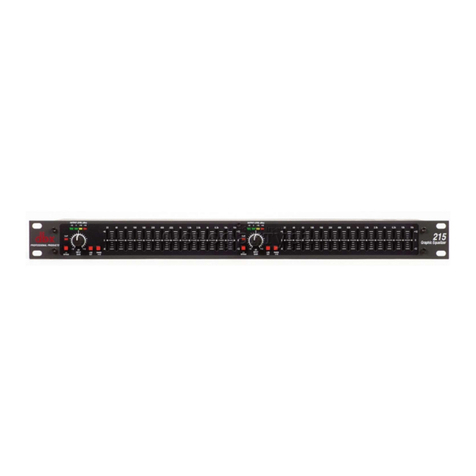
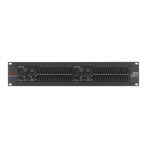
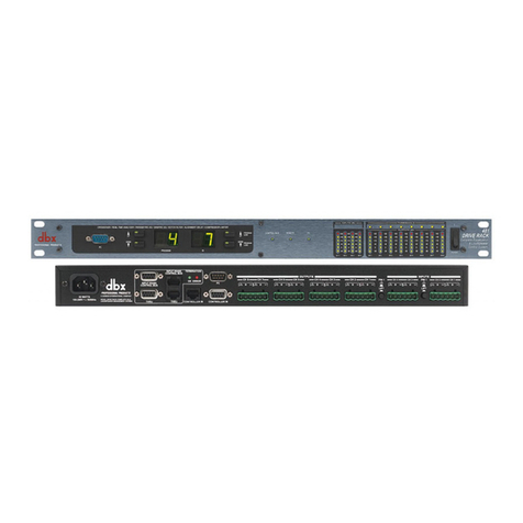
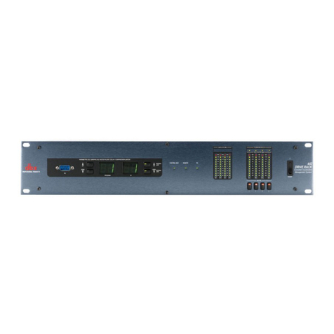
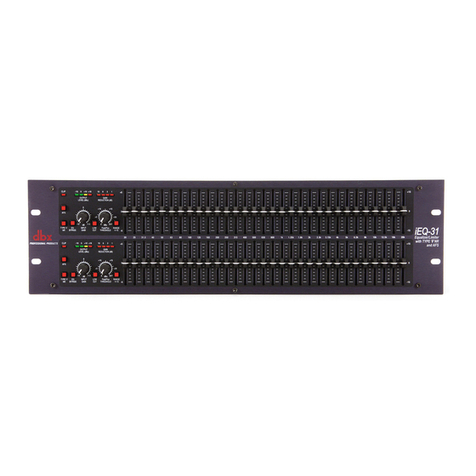
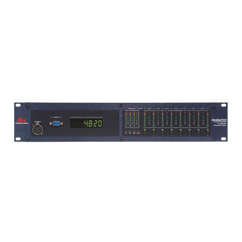
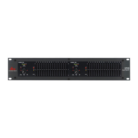
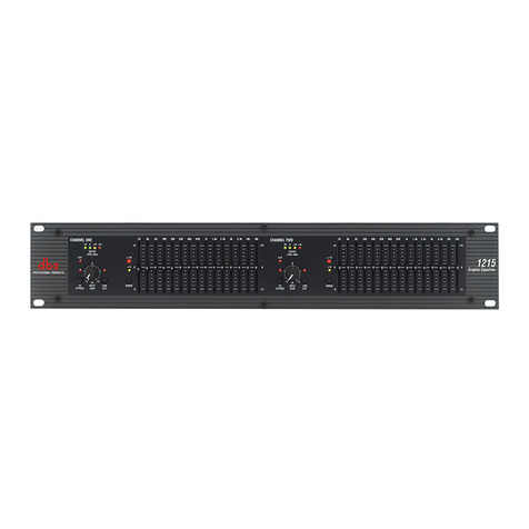
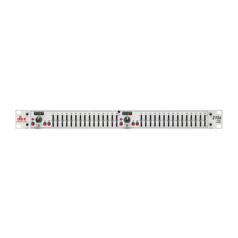
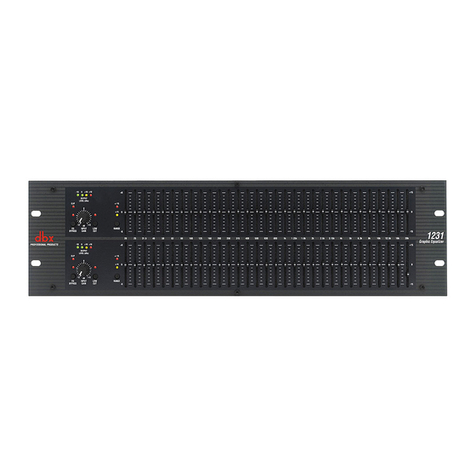
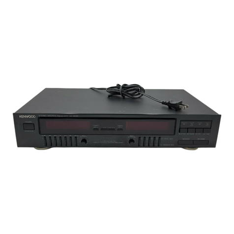
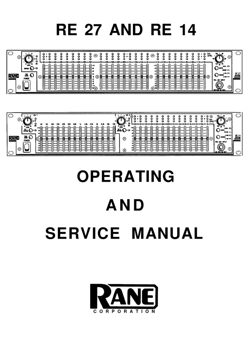
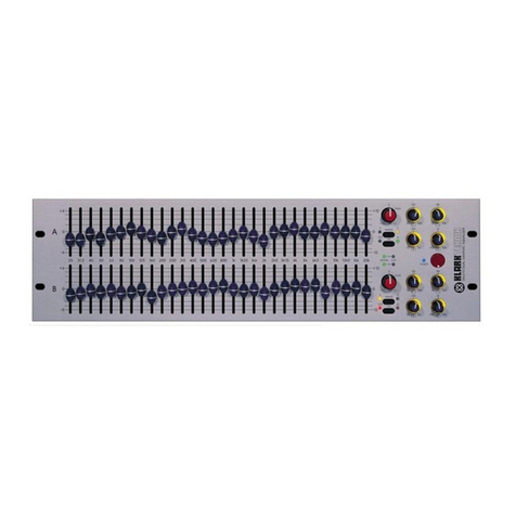
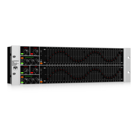
POWER SWITCH:Turns the equalizer's power ON or OFF. Power ON is indicated by the lighted power
LED.
POWER LED: Lights to indicate that the equalizer is turned on.
EQ IN/OUT:This switch removes the equalizer's input gain and individual slider controls from the signal
path. This does not, however, affect the HI CUT and LOW CUT filters. The entire equalizer is
enabled when the switch is in.
BOOST/CUT RANGE SELECTION SWITCH:The switch selects which of the two boost/cut ranges the
equalizer will use, either ±6dB or ±12dB (3031C: -10dB or -20dB)
HEADROOM BAR GRAPH:The eight LEDÕs indicate peak levels within the equalizer. The top LED is
3dB below clipping and indicates overload at the post-input gain, pre-EQ and post-EQ points in the
signal path.. Overload at the input amplifier is indicated by the entire LED bar graph getting brighter
when the signal is 3dB below clipping.
INPUT GAIN CONTROL:This control sets the signal level to the equalizer. It is capable of -12dB to
+15dB of gain. Its effect is indicated on the HEADROOM BAR GRAPH.
FREQUENCY BAND SLIDER CONTROL:Each one of these slider potentiometers will boost or cut its
noted frequency by ±6 dB or ±12dB depending upon the position of the BOOST/CUT RANGE
SWITCH (3031C is cut only: -10db or -20db). When all of the sliders are in the center detented posi-
tion, the output of the equalizer is flat (3031C: sliders placed at top position is flat). The frequency
band centers of the 3215 are marked at 2/3rds of an octave ISO spacings. The frequency band cen-
ters of the 3031,3031C, and 3231 are marked at 1/3rd of an octave ISO spacing.
LOCUT FREQUENCY CONTROL AND LOCUT IN/OUT SWITCH:This control varies the cutoff
frequency of the LO-CUT filter. It is variable from 25 Hz to 200 Hz. The roll-off of this filter is 12dB
per octave. The LO CUT IN/OUT switch to the left of this control inserts or removes the LO CUT filter
from the signal path. When the LO CUT IN/OUT switch is pushed IN, the LO CUT filter is IN the cir-
cuit.
HICUT IN/OUT SWITCH:This switch inserts or removes the HI-CUT filter from the signal path. When
the HI-CUT IN/OUT switch is pushed IN, the HI-CUT filter is IN in the circuit.
OPERATING CONTROLS
30 SERIES GRAPHIC EQs
