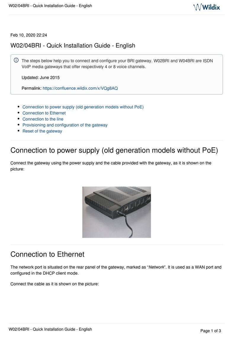
DCB Ether Series User manual

Revised March 25, 2004
Firmware Version 1.4
EtherSeries
Modbus Gateway
EMB-2
User’s Guide


FCC Statement
This device complies with the limits for a Class B digital device,
pursuant to Part 15 of the FCC rules. Operation is subject to the
following two conditions:
(1) This device may not cause harmful interference.
(2) This device must accept any interference received,
including interference that may cause undesired
operation.
CE Marking Warning
This is a class B product. In a domestic environment this
product may cause radio interference in which case the user
may be required to take adequate measures.
Copyright 2002- 2004. All rights reserved.
Version 1.0
All trademarks and trade names are the properties of their
respective owners.


i
TABLE OF CONTENTS
Chapter 1 Introduction........................................1
EtherSeries EMB-02 Functions..........................................2
Other Features......................................................................2
Physical Details....................................................................4
Configuration Switch...................................................5
LED Indicators..............................................................6
Software Requirements ...............................................7
Chapter 2 Installation..........................................9
Overview...............................................................................9
Quick Start ............................................................................9
Installation..........................................................................10
Chapter 3 Terminal/Telnet Configuration.........11
Overview.............................................................................11
Terminal Configuration.....................................................12
Procedure ....................................................................12
Telnet Management..........................................................13
Terminal/Telnet Interface.................................................15
Entering Data......................................................................16
Menu Options....................................................................16
Main Menu Option 1. Setting IP Addresses .........16
Main Menu Option 2. Set Manager/Telnet IP Address
......................................................................................18

ii
Main Menu Options 3 & 4. Serial Port Configuration
......................................................................................19
Main Menu Option 5. MODBUS TCP Configuration
......................................................................................23
Main Menu Option 6. Modbus Serial Configuration
......................................................................................25
Main Menu Option 7. Display Configuration Settings
......................................................................................28
Main Menu Option 8. Reset Configuration to Default
......................................................................................30
Main Menu Option 9. Save and Exit.......................30
Main Menu Option 0. Exit without Saving............30
Chapter 4 Browser Management......................31
Overview.............................................................................31
Connection Procedure......................................................31
Web-based Interface........................................................33
Serial Port Configuration Screen.............................34
Modbus Configuration Screen................................35
LAN Configuration Screen.......................................36
SNMP Configuration Screen....................................37
Configuration Summary Screen...............................38
Port Activity Screen..................................................39
Chapter 5 Operation..........................................39
Operation............................................................................39
Chapter 6 Troubleshooting................................40
Hardware Problems ...........................................................40
Can't Connect via the LAN..............................................41

Introduction
iii
Other Problems...................................................................43
Verify Proper Operation....................................................44
Appendix A Specifications .................................47
EtherSeries Gateway Specifications................................47
RS-232 PIN Assignments .................................................48
Control Signal Operation..................................................49
CABLES ..............................................................................51
Appendix B RS-422/ RS-485 Interface .............53
Introduction........................................................................53
Changing the Setting.................................................53
RS-422 / 4-Wire RS-485 Interface Pinout........................54
2-Wire RS-485 Interface Pinout.......................................55
RS-485 2-wire Fan-out.......................................................55


1
Chapter 1
Introduction
This chapter provides an overview of the
features and capabilities.
ongratulations on the purchase of your new EtherSeries
Modbus Ethernet Gateway. Interfaces include one
10/100BaseT ethernet interface and two RS-232/422/485 serial9-
pin interfaces.
The gateway allows serial MODBUS RTUs to communicate and
interoperate with MODBUS/TCP based controllers. The
MODBUS standard protocol is an asynchronous protocol
designed to connect directly to computer asynchronous ports.
MODBUS has been extended to operate over Ethernet using the
IP protocol suite. This gateway converts between the
MODBUS TCP/IP protocol and MOBUS ASIII/RTU protocols
transparently.
Normal operation would consist of one or more Ethernet based
computers functioning as Modbus Master and one or more
MODBUS slave devices (usually RTUs) connected serially to
the gateway.
By using RS-485, multiple MODBUS slave devices may be
connected to each of the two serial ports on the EMB-02. If
using RS-232, one MODBUS slave device may be connected to
each serial port.
C

EtherSeries EMB-02 User’s Guide
2
The EMB-02 is designed for mounting on a standard DIN rail, or
for direct mounting on a wall. For easy connection to your
LAN, the gateway supports 10BaseT or 100BaseT with auto-
sensing.
EtherSeries EMB-02 Functions
The gateway allows serial MODBUS RTUs to communicate and
interoperate with MODBUS/TCP based controllers. The
MODBUS standard protocol is an asynchronous protocol
designed to connect directly to computer asynchronous ports.
MODBUS has been extended to operate over Ethernet using the
IP protocol suite. This gateway converts between the
MODBUS TCP/IP protocol and MOBUS ASCII/RTU protocols
transparently.
The EMB-02 enables one or more MODBUS controllers to
communicate with modes ASCII/RTU based serial RTUs. It will
not allow MODBUS/TCP RTUs to operate with a serial
MODBUS controller.
Other Features
Dual Serial Ports
The EMB-02 contains two serial ports. The two serial
ports are independent, and may be used with different
hosts and different serial protocols (RTU/ASCII) as well as
different MODBUS address ranges and timeouts.
Multiple Hosts
The EMB-02 may communicate with multiple host controllers.

Introduction
3
Upgradeable Firmware
Firmware upgrades are downloadable to the gateway. The utility
program required for this, and the actual firmware upgrades, are
available from your dealer. A Windows 95/98/XP/NT
workstation is required to run the download software.

EtherSeries EMB-02 User’s Guide
4
Physical Details
The EMB-02 front panel is shown below.
Figure 1: EtherSeries EMB-02
1Power port Connect the power adapter here.
210/100Base-T
port Connect LAN cabling here.
3Red LED RUN Indicator
4Red LED LAN Indicator.
5RS-232 Port 1 DE-9 (DB-9) Serial Interface
6RS-232 Port 2 DE-9 (DB-9) Serial Interface.

Introduction
5
Configuration Switch
There is a momentary action push button switch on the right of
the power connector behind a small hole. Pressing this switch
places the unit in configuration mode and is used only when
configuring the unitvia the serial port, as explained inChapter
3 - Configuration. Return from configuration mode by exiting
the configuration menu or by power cycling the unit. This
switch may be depressed with a tiny screw driver or stiff wire.
(A straightened paper clip works nicely).

EtherSeries EMB-02 User’s Guide
6
LED Indicators
There are two red LED indicators on the panel below the LAN
connector and two green LED indicators adjacent to the serial
ports.
LED Indicators
•The LAN LED is the Ethernet Status indicator. It is lit when
there is a valid 10/100BaseT Ethernet connection.
•This LED flickers off and on with activity on the Ethernet
(even if the activity isn't directly to this unit).
•The green LEDs flicker off and on with EMB-02 transmit
activity on the two serial port.
•The red RUN LED flickers off and on with ethernet transmit
activity from the EMB-02.

Introduction
7
Package Contents
You should find the following items packaged with your
EtherSeries product:
•The EtherSeries Unit
•Power Adapter (or power supply)
•This User’s Guide
If any of the above are missing, contact your dealer
immediately.
Software Requirements
The EMB-02 supports MODBUS/TCP on the Ethernet interface
and MODBUS ASCII and MODBUS RTU on the serial ports.
It may be configured using any terminal or terminal emulation
software on a PC via serial port one. Any standard telnet
program may be used to telnet to the unit for configuration, or
any standard web browser may be used for configuration once
the unit has a valid IP address configured. Since any terminal
program or web browser may be used when configuring the
unit, there is no supplied configuration software.


9
Chapter 2
Installation
This Chapter details the LAN installation
process for the EtherSeries product.
Overview
The EtherSeries products may be configured via a serial port,
telnet, or web browser. Initially, the configuration of an IP
address must be performed using the serial port unless the
default IP address of 192.168.1.1 is appropriate for your Ethernet
network.
To use LAN based configuration, either Telnet or Web Browser
based,an IP address must be configured. The default value of
192.168.1.1 may not work with your network.
Terminal Mode configuration may be performed at any time,
and no IP address is required. See Chapter 3 for details.
Quick Start
Quick start instructions are on the next page. Installation is an
easy process that is basically… plug it in, configure IP,
configure MODBUS, and configure the serial ports.

EtherSeries EMB-02 User’s Guide
10
Installation
1. Connect the Network Cable
The EtherSeries network interface is auto-sensing. Simply
connect your network cable to the appropriate connector on the
rear panel.
2. Connect the Power Adapter Cable
Plug in the power adapter cable. After about a 4 second boot
process the unit is ready for operation. Some configurations
require wiring to a screw-terminal block.
3. Configure an IP Address Information
Using either the default address and telnet or a web browser OR
using a serial port and a terminal emulation, configure the IP
and Modbus/TCP information. At a minimum, the IP address
and port number must be configured.
4. Configure a Serial Port
Configure the appropriate serial ports for the proper Modbus
protocol, slave address range, and timeouts.
5. Configure the Modbus Host.
You are now ready to use the EtherSeries Gateway. Configure
the Modbus/TCP host computer and the serial RTUs for proper
operation and start using it!

Configuration
11
Chapter 3
Terminal/Telnet
Configuration
This Chapter describes how to manage the
EtherSeries product using Terminal, or Telnet
mode. Web Browser mode management is
detailed in Chapter 4.
Overview
The EtherSeries unit may be managed using any of the
following methods:
•Web Browser - After installing the unit in your LAN, use
your Web Browser for management. See Chapter 4 -
Browser Configuration for details.
•Terminal Mode - Use a serial cable connection and a
communication program. This is often required prior to
other modes in order to configure a compatible IP address
into the unit.
•Telnet Mode - After installing the unit in your LAN,
manage it using Telnet.
Both Terminal and Telnet modes provide the same user
interface.

EtherSeries EMB-02 User’s Guide
12
Terminal Configuration
Terminal configuration requires the following:
•PC with terminal emulation program, or a dumb terminal.
•Serial cable to connect the PC to the unit. See the
Appendix for cable requirements. A Crossover (null
modem) cable is required when using a 9-pin PC port.
•Serial port 1 must be configured as an RS-232 port. This is
the factory default configuration.
Procedure
1. Connect the unit to your PC or terminal.
2. Connect the unit to the power supply.
3. Press the configuration setup switch momentarily. It is
located to the side of the power connector and accessed
through a small hole. Use a small pen or paper clip to
access the switch.
4. Configure the terminal program with the following settings.
Setting Value
Flow control protocol None
Speed 9600
Data 8 bits
Parity None
Stop Bit 1
5. Connect your terminal program to the appropriate port (e.g.
COM 1).
This manual suits for next models
1
Table of contents
Other DCB Gateway manuals
Popular Gateway manuals by other brands
AudioCodes
AudioCodes MediaPack 1 Series Hardware installation manual
Neptune
Neptune R900 v4 Installation and maintenance guide

NETGEAR
NETGEAR Sprint 6100D Get started

ioLIVING
ioLIVING Gateway Medium user manual
Elcon
Elcon ELCONnect next BIG 101 Series user manual
socomec
socomec DIRIS Digiware M-50 quick start guide
EnOcean
EnOcean Dolphin USB 500T Preliminary user's manual
ZyXEL Communications
ZyXEL Communications P-873HNUP-51B quick start guide
ZURN
ZURN ZGW-LORA-W1 installation guide
Teltonika
Teltonika TRB140 quick start guide
Vanderbilt
Vanderbilt SPCG310 quick start guide
ZyXEL Communications
ZyXEL Communications LTE7410 quick start guide
