DCB FT-66 Series User manual

FT-66xx Quick Start Guide
Overview
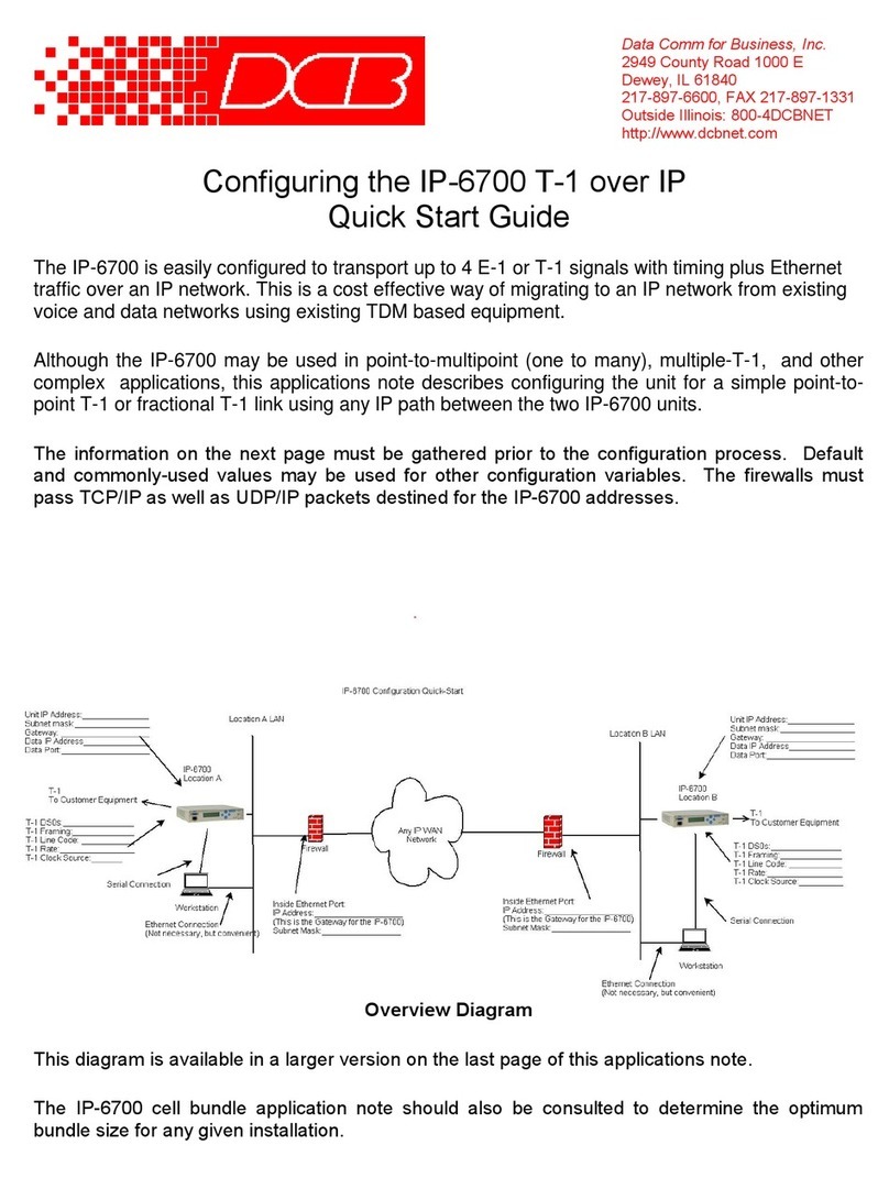
This quick-start guide will walk you through the minimum steps necessary to setup a pair of FTs to
tunnel a private network over a public network. It will not go into detail, but will touch upon the steps
and the order they should be performed. The steps should be repeated for each FT device except where
noted.
The FTs use a client-server architecture. ne unit is designated as the server. It listens for connections
from clients. ne or more clients may be configured to connect to the server. For our walk-through,
please refer to the following diagram. Addresses in the diagram are intended as an example. A blank
copy of this diagram, which you may use to plan your configuration, can be found on the last page of
this document.
Step 1: Setting Initial LAN1 I address
LAN1's default IP address is 192.168.0.1 with a subnet mask of 255.255.255.0. LAN1 will also be
running a DHCP server, assigning addresses in the range 192.168.0.101 through 192.168.0.109. You
can skip to the next step if your computer is configured with an IP address on the 192.168.0.0/24
subnet.
You can change the LAN1 IP address and reset the FT-66xx to defaults through the C M port. The
C M port operates at 9600 baud, 8 data, 1 stop, no parity, no flow control. You will need a null-
modem cable to connect a PC C M port.
4/16/2020

FT-66xx Quick Start Guide
To enter serial setup mode, attach the serial cable and press <enter> on your terminal. You should then
see a login prompt. Login using the name “setup” and follow the on-screen instruction.
Step 2: Accessing the Web Interface
To access the FT-66xx web interface use the following URL. Please note that it is https and not http.
https://192.168.0.1
f course, if you changed the LAN1 IP address using the C M port, please use the new address in the
above URL.
You will get a security warning, then the web browser should pop up an authentication screen. If this
does not happen, see the Important Notes below. Login using the name “admin”. Leave the password
field blank. The name and password fields are case sensitive.
Important Notes:
●After initial TLS negotiation, some web browsers will display a blank page. If this
happens, press the refresh button.
●Your web browser must support the TLS 1.0 protocol. If you have trouble connecting,
check your web browser options to make sure TLS 1.0 is enabled. For IE, you will find
the TLS 1.0 setting under Advanced/Settings. For Firefox you will find it under
Preferences/Advanced/Security.
●Internet Explorer Version 7 and newer or Firefox version 2 or newer are recommended.
lder versions of web browsers may fail due to TLS negotiation issues.
●Firefox, Netscape, and Mozilla will not use the TLS 1.0 protocol if they have
encountered an error with a server. You must exit all instances of the browser then
restart it to clear the error condition.
Setup through the web interface is performed through web forms. There is a menu bar on the left side
of the window where you navigate and select the active form. The active form is displayed on the
right. You make changes to the form, then press the “submit” button to send the changes to the FT-
66xx. If you navigate to a different form without submitting it first, any changes will be lost.
As you go through the forms, you will notice that the each configuration item is hyper-linked. Clicking
the hyper-link will take you to a help page describing the configuration item in more detail.
Step 3: Configure LAN1
LAN1 will reside on your private network. Navigate to the LAN1 – IP Configuration form. Set the IP
address and subnet mask. The other fields on this page are typically not needed and may be left blank.
After making any changes, don't forget to press the “submit” button.
4/16/2020

FT-66xx Quick Start Guide
The LAN1 DHCP server is enabled by default to make it easier to do initial setup. However, in most
cases you will not want it running. It will interfere any other DHCP servers you may have on your
network. Navigate to the LAN1 – DHCP_Server form. Disable the DHCP server, or configure it
appropriately for you network.
Step 4: Activate Changes
If you changed any of the LAN1 settings, now is a good time to Activate Changes and switch over to
using LAN1's new IP address. After you activate the changes, you will need to change the URL in your
web browser to the FT-66xx's new IP address.
Step 5: Store Configuration
If you had changes to activate, then you should now Store Configuration. It is usually best to activate
changes first, then store them. This give you a change to verify that the changes are K before
committing them to non-volatile storage. If the changes were bad, you can simply power-cycle the unit
and get back to your previously working configuration.
Step 6: Configure LAN2
LAN2 is the primary link to the Internet. Navigate to the LAN2 – IP Configuration form. Set the IP
address, subnet mask, and gateway. Unlike the LAN1 configuration, a gateway address is almost
always needed for LAN2. It should be the address of your Internet router. The other fields on this page
are typically not needed and may be left blank.
LAN2 can also connect to the Internet using PPPoE. If your ISP requires PPPoE, navigate to the
LAN2-Mode form and set the mode to PPPoE. Then navigate to the LAN2 - PPPoE Configuration
form and set the configuration per you ISP's instruction. In most cases, you will only need to set the
User Name and Password fields.
Step 7: Configure LAN3
If you have a secondary Internet connection it can be used as backup link. Configure LAN3 in the
same manner as LAN2. therwise, navigate to the LAN3 – Mode form and disable it.
Step 8: Set the Clock
It is important to set the FT-66xx clock prior to generating the security keys. These keys contain time-
stamps, and large clock discrepancies can result in certificate errors. Navigate to Administration – Set
Clock to manually set the time. ptionally, navigate to Tools – NTP and configure NTP. If relying on
an NTP server to obtain the time, please verify that the time is successfully set prior to generating any
keys.
4/16/2020

FT-66xx Quick Start Guide
Step 9: Tunnel – Generate CA Key
This step will only be performed once. You should not repeat it for each FT device.
A USB flash drive was included with your FT-66xx. Insert the USB flash drive into one of the USB
ports on the FT-66xx. Go to Tunnel – Generate CA Key form. Fill out the form. All of the fields,
except the password fields, are informational. It really doesn't matter what you put in them, but its best
to use information meaningful to you.
The two password fields are the most critical. n this form, you are creating the password. Enter the
same password in both places. Make sure to use a password you can remember. You will need it later
when you generate local keys.
Press the “submit” button, then wait patiently. Key generation can be a slow process. Also, make sure
to read any error messages. USB flash drives sometimes fail to register correctly. Upon error, it may
be necessary to remove the USB drive, wait 5 or so seconds, then reinsert the drive.
If you forget your password, there is no way to recover it. Your only option is to generate new a CA
key, which will overwrite the old one.
Step 10: Tunnel – Generate Local Key
This step will be performed for each FT device. As a reminder, make sure the FT’s clock has been set
before proceeding.
Insert the USB flash drive, containing your CA Key, into one of the USB ports on the FT-66xx.
Navigate to the Tunnel – Generate Local Key form. For the name field, use a unique and descriptive
name for the device. For example, the server FT-66xx could be named “Home ffice Server” and the
client FT-66xx could be named “Remote ffice Client”. The lifetime field specifies the number of
days that the key is to be certified. Unless you plan to frequently change your keys, its best to choose a
big number.
For the password field, enter the same password you set when you generated the CA key.
Press the “submit” button, then wait patiently. Key generation is a slow process. Also, make sure to
watch for any error messages. USB flash drives sometimes fail to register correctly. Upon error, it
may be necessary to remove the USB drive, wait 5 or so seconds, then reinsert the drive.
Remove the USB Flash drive and store it in a safe place. You will need it in the future if you plan to
add more client FT-66xx devices to your server.
Step 11: Tunnel – Mode
Navigate to the Tunnel – Mode form and select whether the FT-66xx is operating as the server or the
client.
4/16/2020

FT-66xx Quick Start Guide
Step 12: Tunnel – Configuration (Server)
This step is only performed for the server tunnel.
The server will default to listening to TCP port 22. For most applications there is no need to change
this value. However, if you need to use a different TCP port for you application, navigate to the Tunnel
– Configuration form and set the port number. You may optionally have the server listen to a second
port number, but again, this is usually not necessary.
Step 13: Tunnel – Configuration (Client)
This step is only performed for the client tunnel(s).
Navigate to the Tunnel – Configuration form. Set the “Connect to Server” field to the Server's LAN2
IP address. Referring to example setup, this would be the 12.29.144.4 address. Set the “port” field to
the same port number set in the previous step. Set the “via interface” to LAN2.
If you have a backup Internet connection on LAN3, you can also set the fail-over fields. In our
example configuration this wold be the 69.252.228.2 address. The “port” field is the same as above
and the “via interface” would be LAN3.
Note: If you have a backup link at client side but not at the server side, it is K to use the same
“Connect to Server” for both the primary and fail-over settings. nly the “via interface” field needs to
be different. Likewise, if you have a backup link at the server side but not at the client side, the “via
interface” would both be set to LAN2 but the “Connect to Server” would differ for the primary and
fail-over settings.
Step 14: Activate & Store Changes
Activate and save the final configuration. You can now navigate to the Status – Interface page and
verify LAN interfaces. You can also navigate to the Status – Tunnel Log page to determine the state of
the tunnel.
4/16/2020

FT-66xx Quick Start Guide
4/16/2020
This manual suits for next models
1
Table of contents
Other DCB Network Hardware manuals
Popular Network Hardware manuals by other brands
Blackwire
Blackwire DMX-Bridge Quick setup
IOCELL
IOCELL NetDISK 351UNE user manual

Juniper
Juniper QFX10016 quick start
Crestron
Crestron Network Device PWE-4803RU installation guide

Ventev
Ventev TerraWave Rapid Deployment Kit with Battery Backup... Assembly instructions

Airlink101
Airlink101 AWMB100 Quick installation guide
