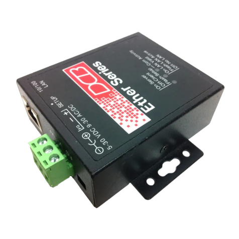
DCB EtherPath User manual

Revised June 3, 2004
Firmware Version 5.3
EtherPath
User’s Guide

FCC Statement
This device complies with the limits for a Class B digital device,
pursuant to Part 15 of the FCC rules. Operation is subject to the
following two conditions:
(1) This device may not cause harmful interference.
(2) This device must accept any interference received,
including interference that may cause undesired operation.
CE Marking Warning
This is a class B product. In a domestic environment this product
may cause radio interference in which case the user may be required
to take adequate measures.
Copyright 1998…2004. All rights reserved.
Version 5.3
All trademarks and trade names are the properties of their respective
owners.

i
TABLE OF CONTENTS
Chapter 1 Introduction............................................1
EtherPath Functions.....................................................2
Other Features ............................................................. 4
Physical Details...........................................................6
Chapter 2 Installation ............................................11
Overview...................................................................11
LAN Installation........................................................11
Chapter 3 Terminal/Telnet Configuration...........13
Overview...................................................................13
Terminal Configuration.............................................14
Telnet Configuration .................................................15
Terminal/Telnet Interface..........................................17
Chapter 4 Browser Configuration........................36
Overview...................................................................36
Connection Procedure ...............................................36
Web-based Interface..................................................38
Chapter 5 Operation ..............................................53
Client/Server Point-to-Point (Nailed-Up) Mode.......53
Server Mode..............................................................55
Client/Server Point-to-Multiple-Point
(EtherModem) Mode.................................................55
Client (Reverse Telnet) Mode...................................58

ii
Chapter 6.................................................................60
Configuration Security...........................................60
Overview...................................................................60
Level 0:......................................................................61
Level 1:......................................................................61
Level 2:......................................................................62
Level 3:......................................................................62
Chapter 7 Troubleshooting....................................64
Hardware Problems...................................................64
Can't Connect via the LAN........................................66
Other Problems..........................................................68
Checking Device Operation.......................................70
Appendix A Specifications.....................................71
EtherPath Specifications............................................71
RS-232 PIN Assignments..........................................72
Control Signal Operation...........................................73
CABLES....................................................................75
Appendix B Programming.....................................77
Introduction...............................................................77
Description and Behavior..........................................78
Application Notes......................................................81
Appendix C AT Command Summary ..................82
AT Commands...........................................................82
AT Command Responses ..........................................83

Introduction
iii
AT Command Operation...........................................83
Appendix D RS-422/ RS-485 Interface.................84
Introduction...............................................................84
RS-422 / 4-Wire RS-485 Interface Pinout.................85
2-Wire RS-485 Interface Pinout................................86


1
Chapter 1
Introduction
This chapter provides an overview of the
EtherPath's features and capabilities.
ongratulations on the purchase of your new EtherPath. The
EtherPath is a versatile product that enables serial communications
devices to operate via Ethernet. It is designed to easily connect a
serial port device to your network. A remote PC or other serial
device can then be used to monitor, configure, manage and send or
receive data to the serial port device through the LAN/WAN.
The EtherPath can receive data from any Serial device, convert the
data to a valid IP packet, and transmit that data over the
LAN/WAN. Serial devices can then be accessed from anywhere on
your LAN/WAN by any workstation computer running telnet,
dedicated software, or COM: port redirection software. Two
EtherPaths may be used in “nailed-up” mode to build a “RS-232
path” through the WAN/LAN. Multiple EtherPaths may be
connected via Ethernet by using them in Point-to-Multiple point
"AT Dial " mode.
Some serial port devices in common use are Bar Code Readers,
UPSs, SCADA RTUs, security alarms, access control devices, time
clocks, POS terminals, and multiplexers.
For easy connection to your LAN, the EtherPath supports both
10BaseT and 100BaseT connections.
C

EtherPath User’s Guide
2
EtherPath Functions
The EtherPath can be used in several modes – simple Client/Server
or Server, as illustrated below, point-to-multiple-point
(EtherModem) Client/Server, and reverse telnet Client. These
modes are described below.
Figure 1: Modes of Operation
Client/Server Mode
In this mode, two EtherPaths are used. Both are connected to serial
RS-232 devices. This is termed a “Nailed-Up” connection.
•The "Client" EtherPath will automatically establish a
connection to the "Server" EtherPath upon power-up.
•The device on one EtherPath communicates with the other
serial port device as if it was directly connected via a serial port
cable.

Introduction
3
•The EtherPaths and the LAN are completely transparent to PC
application and serial port device.
Server Mode
This mode requires only a single EtherPath. The EtherPath is
connected to the serial port device, and to the LAN.
Users on the LAN can then connect to the serial port device and
communicate with it via Telnet, using any assigned IP and port
address. Most LAN connected workstations provide support for
communication via Telnet.
A special-purpose utility program or port redirector program may be
used instead of Telnet, or the user may create custom software using
Visual Basic, C++, or other network programming tools. By using
port redirection, the EtherPath may function as a remote serial port
on a PC.
Point-to-Multiple-Point (EtherModem) Mode
Point-to-multiple-point (EtherModem) operation allows a single
EtherPath running in client mode to connect to multiple server-
mode EtherPaths, one at a time, under the control of the attached
RS-232 device. The client operates similar to a modem with “AT”
dialing enabled. The attached device treats the EtherPath as if it
was a modem, using remote IP addresses instead of telephone
numbers.
Reverse Telnet (Telnet Client) Mode
This mode requires only a single EtherPath. The EtherPath is
connected to the serial port device, and to the LAN.
The EtherPath will connect to most remote telnet servers under user
control by using “reverse telnet” or telnet client operation. The

EtherPath User’s Guide
4
EtherPath will connect to any port number under user control with
either hardware (pin6) dialing or AT dialing.
By using the "AT Dial" commands, the connected device can direct
the EtherPath to connect to multiple remote devices, one at a time.
Other Features
Automatic Connection
When used in Client/Server mode, the “Client” EtherPath will
automatically establish a connection to the “Server” EtherPath on
power-up, or under the control of an RS-232 control signal.
AT Commands
The EtherPath responds to most common AT commands when in
the Client mode. Commands are listed in the Appendix.
Connection Recovery
The EtherPath uses a proprietary protocol to ensure the client/server
session always exists on TCP/IP. When data hasn't been transferred
through the connection for some time, the EtherPath will
communicate with the other device (either EtherPath or PC) to
ensure that the connection is still open.
If there is no response, the device will reset to the initial state, and
attempt to reconnect.
Also, if the RS-232 link is broken, it will be reconnected
automatically if possible (when in Hardware-connect mode).
This operation is described in the Appendix.
Protocol Conversion
The RS-232 device at the client end and the device at the server end
of a link do not have to use the same communications protocols on

Introduction
5
the RS232 link (speed, parity, flow control). The EtherPaths will
convert the data to the correct protocol.
Configuration Security
Etherpath configuration may be “Locked-down” or restricted in
several ways. The web Browser interface, telnet configuration
interface, and SNMP configuration interfaces may be disabled.
Specific IP addresses may be configured into the unit to disallow
configuration from any other than the desired management
workstations.
Upgradeable Firmware
Firmware upgrades are downloadable to the EtherPath. The utility
program required for this, and the actual firmware upgrades, are
available from your dealer.

EtherPath User’s Guide
6
Physical Details
The EtherPath front and rear panels are shown below.
Figure 1: EtherPath
1Power port Connect the power adapter here.
210/100Base-T
port Connect lan cabling here.
3Red LED Client/Server/Setup Indicator
4Red LED LAN Activity Indicator.
5Green LED Connection Indicator.
6RS-232 Port DE-9 (DB-9) RS-232 Interface.

Introduction
7
Configuration Switch
There is a momentary action push button switch on the right side of
the unit behind a small hole. Pressing this switch places the unit in
configuration mode and is used only when configuring the
EtherPath via the serial port, as explained in Chapter 3 -
Configuration. Return from configuration mode by exiting the
configuration menu or by power cycling the unit. This switch may
be depressed with a tiny screw driver or stiff wire. (A straightened
paper clip works nicely).

EtherPath User’s Guide
8
LED Indicators
There are two red LED indicators on the rear panel adjacent to the
LAN connector and one green LED indicator on the front panel
between the 9-pin serial connectors.
Rear Panel LED Indicators
•The lower red LED is the Ethernet Status indicator. It is lit
when there is a valid 10/100BaseT Ethernet connection. This
LED flashes with activity on the Ethernet (even if the activity
isn't directly to this unit).
•The upper red LED is multi-function indicator. The different
states indicated by these LED are described below.
Red LED
Indication Status Description
OFF Client Mode
ON Server Mode
Rapid Flashing Setup Mode
Irregular Flashing Power On Self Test
-or-
Firmware Download

Introduction
9
Front Panel LED Indicators
•There is one front panel green LED indicator. This
corresponds to Port 1 status.
•This LED is a multi-function indicator. The different states
indicated are described below.
Green LED
Indication Status Description
OFF Pin 6 input is low and
there is no telnet
connection
ON Pin six is high and
there is no telnet
connection
Rapid Flashing Telnet session is
active
Slow Flashing Pin 6 is tied high via
Software and there is
no telnet connection

EtherPath User’s Guide
10
Package Contents
You should find the following items packaged with your EtherPath:
•The EtherPath Unit
•Power Adapter (typical)
•This User’s Guide
If any of the above are missing, contact your dealer immediately.
Software Requirements
The EtherPath supports the following protocols.
•TCP/IP
•UDP
•ARP
•ICMP
•TELNET
•SNMP
The EtherPath has been tested to work with:
•All versions of Windows
•Unix - SCO, Sun, AIX, Linux, etc.
•Macintosh
•Most serial devices such as scanners, RTUs, SCADA
hosts, alarm controllers, POS devices, PCs, terminals, etc.
•VOIP multiplexers, digital video cameras, video
conferencing systems, etc.

11
Chapter 2
Installation
This Chapter details the LAN installation process
for the EtherPath.
Overview
For Telnet Mode or Web Browser Mode configuration, LAN
installation is performed before configuration. There must also be a
valid IP address in the unit prior to configuration with these
methods. The default IP address may not work with your
network.
If you use Terminal Mode configuration, then the configuration
should be performed prior to LAN installation. See Chapter 3 for
details.
LAN Installation
1. Connect the Network Cable
•The EtherPath network interface is auto-sensing. Simply
connect your network cable to the appropriate connector on the
EtherPath panel.

EtherPath User’s Guide
12
2. Connect the Power Adapter Cable
Plug in the power adapter cable. After about a four second boot
process the EtherPath is ready for operation.
Only use the power adapter provided
with the EtherPath. Using a different
one may cause hardware damage.
3. Connect the Serial Port Device
Connect the serial port device to the serial port on the EtherPath. If
connecting to a PC 9-pin port, a cross-over (null modem) cable
is required. See the Appendix for wiring details.
Then apply power lead to the serial port device.

13
Chapter 3
Terminal/Telnet
Configuration
This Chapter describes how to configure the
EtherPath's using Terminal configuration mode or
Telnet configuration mode. Web Browser mode is
covered in the next chapter.
Overview
The EtherPath can be configured using any of the following
methods:
•Web Browser - After installing the EtherPath in your LAN,
use your Web Browser for configuration. See Chapter 4 -
Browser Configuration for details.
•Terminal Mode - Use a serial cable connection and a
communication program. The advantage of this method is that
you give the EtherPath a compatible IP Address prior to
installation in your network.
•Telnet Mode - After installing the EtherPath in your LAN,
connect to it using Telnet for configuration.
Both Terminal and Telnet modes provide the same user interface.

EtherPath User’s Guide
14
Terminal Configuration
Terminal configuration requires the following:
•PC with terminal emulation program, or a dumb terminal.
•Serial cable to connect the PC to the EtherPath. See the
Appendix for cable requirements. A Crossover (null modem)
cable is required when using a 9 pin PC port.
Procedure
1. Connect the EtherPath to your PC or terminal using a null-
modem cable.
2. Press the configuration setup switch momentarily. It is located
on the side of the EtherPath and accessed through a small hole.
Use a small pen or paper clip to access the switch.
3. Start the terminal program and configure the terminal program
with the following settings.
Setting Value
Flow control protocol None
Baud rate 9600
Data 8 bits
Parity None
Stop Bit 1
4. Connect your terminal program to the appropriate port (e.g.
COM 1).
Table of contents
Other DCB Server manuals
Popular Server manuals by other brands
Avocent
Avocent Cyclades ACS Installation/administration/user guide

Lenovo
Lenovo ThinkServer TS200v Garanzia e informazioni di supporto

Systech Corporation
Systech Corporation iNS/3000 Hardware manual

Inspur
Inspur NF8480M5 user manual

Intel
Intel SR1560SFHS - Server System - 0 MB RAM Service guide
Oracle
Oracle SPARC T5-1B Service manual

HPE
HPE ProLiant DL360 Gen10 user guide

KYLAND Technology
KYLAND Technology PTS-10 Operation manual

Fujitsu
Fujitsu PRIMERGY T850 System configurator and order-information guide

IBM
IBM Power 750 Express 8233-E8B manual

Gigabyte
Gigabyte R143-E30-AAB1 user manual

Supermicro
Supermicro SUPERSERVER 1018R-WC0R user manual