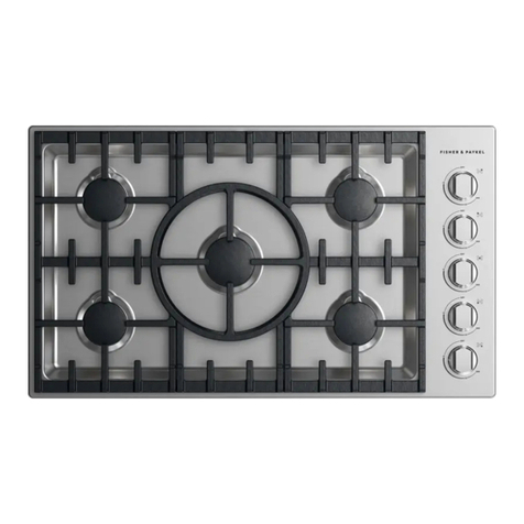
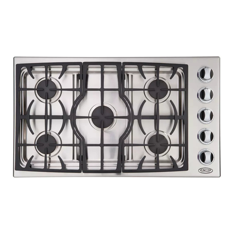
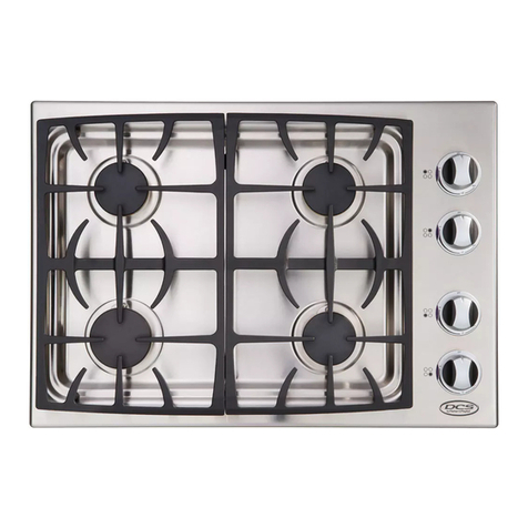
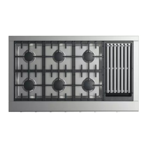
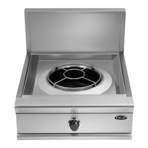
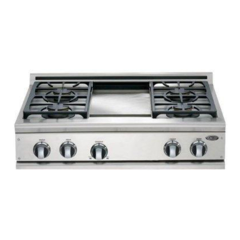
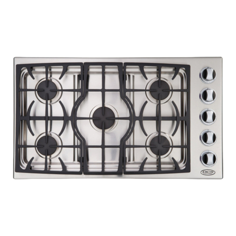
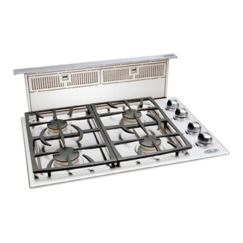
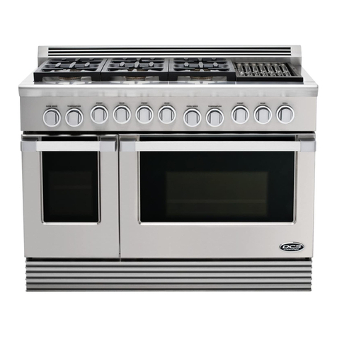
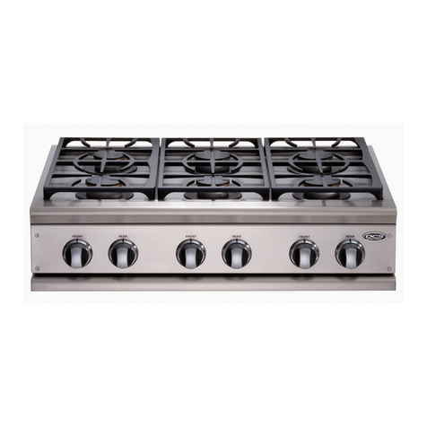
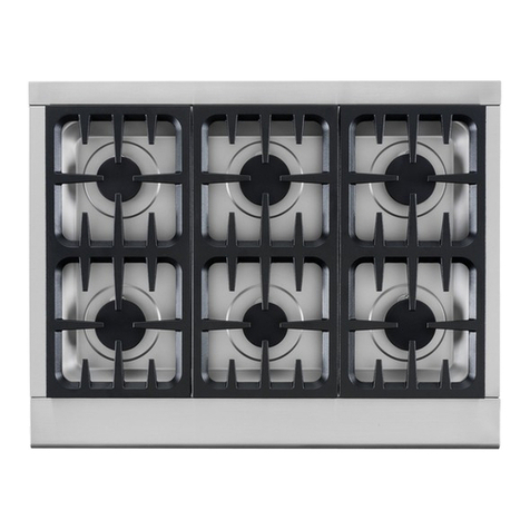
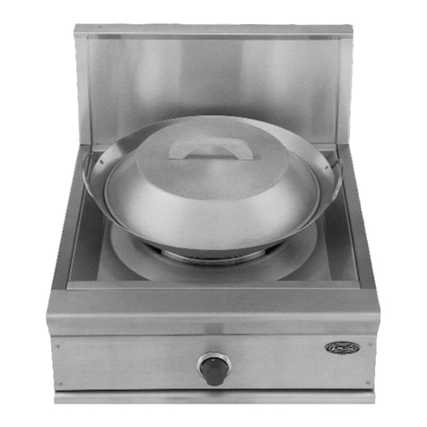
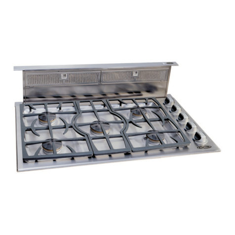
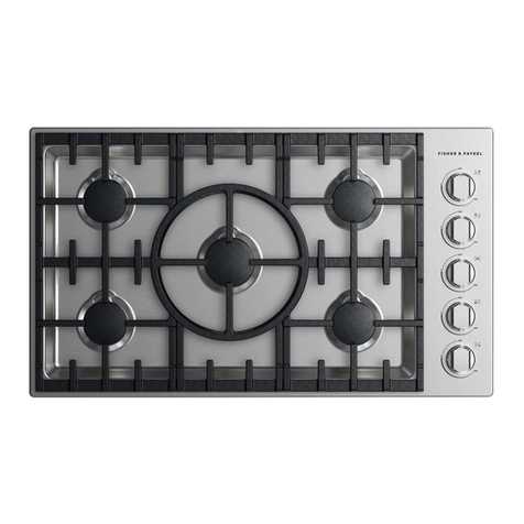
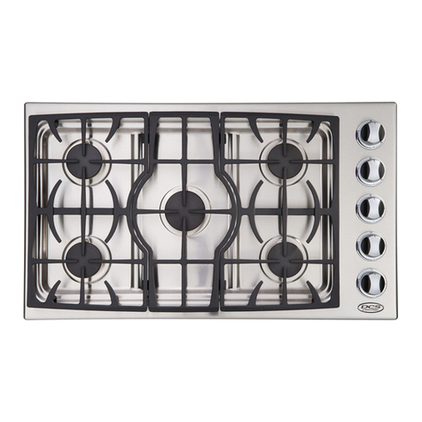
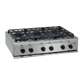
DCS CS-366 User manual

PERFECT _EAT_ _
CSCO0
Installation Guide
MODELS:
CS-366
CS-364GL
CS-364G
CS-4g4GG
CS-486GL
CS-486GD
CS-485GD

A MESSAGE TO OUR CUSTOMERS
Thank you for selecting this DCSC5 Cboktop. Because of this appfiance's unique features we have developed
this Instaflation Guide. It contains valuable information on how to properly install your new appliance for
years of safe and enjoyable cooking.
For your convenience, product questions can be answered by a DCS Customer Service Representative by
DCS
Attention: CustomerService
800Skylab Road
Huntington Beach,CA92647
www.dcsappfiances.com
WARNING
If the information in this manual is not followed exactly, a fire or explosion
may result causing property damage, personal injury or death.
PRECAUTION
Do not store or use gasoline or other flammable vapors and liquids in the
vidnity of this or any other appliance.
FOR YOUR SAFETY
IF YOU SMELL GAb:
[] Do not try to light any appfiance.
[] Do not touch any electrical switch; do not use any phone in your building.
[] Immediately call your gas suppfier from a neighbor's phone. Follow the gas
suppfier's instructions.
[] If you cannot reach your gas suppfier, carl the fire department.
[] Instaflation and service must be performed by aquafified installer, service
agency or the gas supplier.
PLEASE RETAIN THIS MANUAL FOR FUTURE REFERENCE°

TABLE OF CONTENTS
INTRODUCTION ..................................................................................................................................................................3
MODELS ....................................................................................................................................................................................4
PLANNING THE INSTALLATION ..............................................................................................................................s
UNPACKING AND HANDLING .................................................................................................................................6
VENTILATION REQUIREMENTS ...............................................................................................................................7
CABIN ET PREPARATION .........................................................................................................................................8-I 0
BACKGUARD INSTALLATION .................................................................................................................................11
ELECTRICAL /GAS CONNECTIONS ...................................................................................................................12
HOOK-UP TO GAS SUPPLY ......................................................................................................................................13
TEST AND ADJUSTMENTS .......................................................................................................................................14
INSTALLER FINAL CHECKLIST ...............................................................................................................................15
WIRING DIAGRAMS /SCHEMATICS ...........................................................................................................16-19
CS Cooktop 36"/48"Wiring Diagram .................................................. ] 6
CS Cooktop 36"/48"Wiring Schematic ................................................. ] 7
CS Cooktop 48_5Wiring Diagram ....................................................... 18
CS Cooktop 48_5Wiring Schematic ..................................................... ] 9
HOW TO OBTAIN SERVICE ........................................................................................................................................2o
WARRANTY ..........................................................................................................................................................................21

The DCS Professional CS Cooktops feature a large number of features varying with each model. Aii
models feature a minimum of 4 surface burners, with the option of up to 6 surface burners on all
models. Ail of the 48" and 36" Cooktops feature the possibility of various grill and griddle
combinations. Aii cooktop models require the installation of one of the two offered backguards, if
installed with less than 12"to combustible materhL See page 10.
IMPORTANT INSTALLATION INFORMATION
The cooktops are tested in accordance with ANSi Z21.1 Standard for Househoid Cooking Gas
Appihnces. These cooktops must be installed in conjunction with a suitabie overhead vent hood. (See
Step 2 for ventilation requirements). Due to the professionai high heat capacity of this unit, particuhr
attention shouid be paid to the hood and duct work installation to ensure it meets local building
codes. To eliminate risk of burns or fire by reaching over heated surface units, cabinet storage located
above the surface units should be avoided. Check local building codes for the proper method of
cooktop installation. Local codes vary. Instalhtion,electrical connections, and grounding must comply
with all applicable codes. In the absence of local codes, the cooktop should be installed accordance
with the National Fuel Gas Code ANSI Z223.1-1988 and National Electrical Code ANSI/NFPA 70-1990.
Be sure that the unit being installed is set up for the kind of gas being used. The gas cooktop is shipped
from the factory set and adjusted for natural gas or LP (propane), depending on the specific model
ordered. Verify that the cooktop is compatible with gas supply at the installation site before
proceeding further_ Return cooktop to dealer if unit is not set for site gas supply.

MODELS
48" CS COOl(TOP MODELS
000 0 0 0
CS-484GG CS_486GL CS_486GD
CS_485GD
36" CS COOl(TOP MODELS
fiGS-366 fiGS-364GL RGS-364GD

PLANNING THE INSTALLATION
RECOMMENDED INSTALLATION INSTRUCTION
(If installing a full backguard with the cooktop)
A) Vent Hood
B) Backguard System
C) Cooktop
1} Locate cooktop according to cooktop installation instructions.
2} Measure distance from counter surface to top of trim on cooktop adding 1/8" for backguard
clearance.
3} Transfer this measurement to the wail This wH[ mark the bottom of your backguard.
4} From this [ine measure 30 1/16" up wall[ to mark top of 30" backguard. This is the minimum height
that the bottom of your vent hood can be instaHHed.
5} FoHHowvent hood manufacturer's instaHHation instructions to install[ vent hood.
7} FoHHowbackguard instaHHation instructions to install[ backguard.
8} Connect gas and eHectric connections and sHide cooktop into position.

UNPACKING AND HANDLING
STEP 1:
MOVING AND PLACING THE COOKTOP
NOTE: Ifasolid side cabinet wall exists on one or both sides, you will need to notch the
front corner of the cabinet to match the counter top notch and to provide clearance
for the cooktop front (see page 8).
CAUTION:
Proper equipment and adequate manpower must be used in moving the
cooktop to avoid personal injury or damage to the unit
ANCHORING THE COOKTOP
The cooktops have a shipping weight ofapproximateHy 228 pounds (36" modeHs)and 324 pounds (48"
modeHs). After removaH of packing materhHs, it is recommended that the grates and drip pan (below
knobs) be removed to facilitate handling. This will reduce the weight to about 150 pounds.
[] DO NOT REMOVE THE GRILL OR GRIDDLE ASSEMBLIES.
It may be necessary to remove the cooktop knobs to pass through some doorways. With the knobs
removed a 2%3/8" wide opening is required. Remove the outer carton and packing material from the
shipping base. The cooktop is held to the skid by four straps. After removing the straps, the cooktop
must be lifted and removed from the skid.
The professional cooktop should be moved dose to its final location. Electric and gas connections
should be made (steps 5 & 6 pgs. 12 & 13) and the backguard installed (as required, step 4 pg. 11)
before the cooktop is placed in its final position. The grill and griddle sections are fastened in place at
the front with screws.They are designed to be stationary and not meant to be removed for cleaning.
The griddle has two leveling screws beneath the rear flue cover which can be used to adjust the
griddle to the desired slope.The center screw is for shipping and should be removed.
[] Due to the weight of the cooktop, along with a built-in side frame gasket that is meant to rest and
create a seal on the counter top once installed, it is not necessary to anchor the unit to the counter.

VENTILATION REQUIREMENTS
STEP 2:
A suitable exhaust hood must be installed above the cooktop. The following chart indicates the
minimum blower capacity recommended for hood ventilation.
VENTILATION STANDARD COUNTER ISLAND
UNIT INSTALLATION INSTALLATION
RECOMMENDATIONS RECOMMENDATIONS
HOOD (24" Deep x Unit Width) (30" Deep x 36" at Bottom)
BLOWER *48" COOKTOP
800-1200 CFM 800-1200 CFM
**36" COOKTOP
600-800 CFM 600-1200 CFM
x When installing a unit featuring a grill, select a blower on the high end of recommendation.
__ For aii 36"Cooktop GL models a 1200 CFM ventilation unit is required.
CAUTION:
Ventilation hoods and blowers are designed for use with single waft ducting.
However, some local building codes or inspectors may require double waft
ducting. Consult local building codes and/or local agencies, before starting, to
ensure that hood and duct installation wifl meet local requirements.
Hood blower speeds should be variable to reduce noise and loss of heated or air conditioned
household air when maximum ventilation is not required. Normally, the maximum blower speed is
only required when using the grill. For best smoke elimination, the lower edge of the hood should be
installed a minimum of 30" to a maximum of 36" above the cooktop cooking surface, (step 3 pg. 8). if
the hood contains any combustible materials (i.e.awood covering) it must be a minimum of 36" above
the cooking surface. Due to a high volume of ventilation air, a source of outside replacement air is
recommended. This is particularly important for tightly sealed and insulated homes. A reputable
heating and ventilating contractor should be consulted.

CABINET PREPARATION
STEP 3:
1}To ensure profesMona[ results, the cabinet and countertop openings should be prepared by a
qualified cabinet worker. We recommend having the cooktop available before cutting the opening
for more precise dimension verification.
2} The clearances shown in Fig.5 pg. 10 are required for aii types of backguard installations.
:3}The cooktop is designed to hang from the countertop from its side flanges.The countertop,
however, must be strong enough to support this heavy cooktop, it may be necessary to add a
supporting cheat along each side or other form of support such as a2"x 4"corner brace on each side,
or a deck to set the cooktop on. See Fig.1.
4} The cooktop can be installed in various positions with the front either flush or projecting,
depending on the countertop depth. See Fig.2 & Fig. 4 (cooktop side view).
5} Establish the centeriine of the desired cooktop location, it should be the same as the center of the
overhead ventilation hood.
2"x 4"comer
F
Min.48"WideHood
Min.36" WideHood
/
/
B
/
18"Min. i /'
C@ @ @ @ O o
12"@n.to
Combustible
Material,
i_ EachSide--
i
i CookingSurface
i
1,6" oo
6asSupply. /0
\
::Asdefinedinthe"NationalFuel6asCode"(ANSIZ223.1,LatestEditon). ]
ThelevelofthecooktopmustBeatthesamelevelolabovethecounteltoplevel.j
Fig. 1 CS Cooktop Models
A B C D E F G H
47-7/8" 26-1/2" 8-7/16" 46-5/16" 22-3/4" 8" 7/8" 0-2-1/2"
35-7/8" 26-1/2" 8-7/16" 34-15/16" 22-3/4" 8" 1/2" 0-2-1/2"
CAUTION
36"Min.to
cmebustible
matedal,flom
cookingsuflace

CABINET PREPARATION
STEP 3: (CONTINUED)
6} Cut the openings for the following installation:
l Standard counter top installation, see Fig. 5A
[] Deep counter or island installation, see Fig.5B
NOTE: If the deck is used, the sides or bottom of
the cutout may be solid combustible or
non-combustible meterieL If the bottom
is solid, provide e 6" x6" cutout in the
left reer corner for the ges inlet end
power cord clearance.
Front projects outward as shown
from standard depth cabinet.
_F[ush with cabinets
Front flush with cabinets; a minimum of
25 3/4"cabinet depth required
Fig. 2
@_O
_0
Counter-Sunk Screws
Fig. 3

CABINET PREPARATION
Countertop Levd_
3"To Center Line
of Gas Inlet ---_
1/2"
26 1/2"
22 3/4"-----_
23 1/4"-----_
2 1/2"--_
Cabinet face for installation
with projecting controH pane[
Cabinet face for insta[[afion
with flush controH paneH
)
-_ _- 5/8"
Fig. 4
B_k_\\\ \\\\\\\\ \\\\\\\'\\\\
12"Min.toCombuslibBs'
_ witlloutB_ckgu(ird
36"Minto
¢oml_ustib[es_
Fig. 5
10

BACKGUARD iNSTALLATiON
STEP4:
BACKGUARD KITS:
The backguard is located as shown in
Fig. 6. Secure the backguard to the wall[
behind the cooktop.
Specific instructions for instaHHation of the
full[ backguard or How backguard can be
found packaged with the backguard. See
aHsopage 5.
The backguard must be installed when
there is less than a 12" clearance between
combustibles and the back of the cooktop
(above the cooking surface, see Fig. 5,
pagelO).
Wall Mount
Full Backguard
(Model #'s BGS 3030,
BGS 3036, BGS 3048)
Wall Mount
Low Backguard
(Model #'sBGS 1230, "
BGS 1236,BGS 1248)
Fig. 5
11

ELECTRICAL /GAS CONNECTIONS
STEP 5:
ELECTRICAL CONNECTIONS
Power requirements Cooktop:
[] 120 VAC,60 Hz., singie phase 7 Amp.
[] CS-48:15 Amp. Max.
[] CS-36:15 Amp. Max. (use 15 Amp.circuit)
Always disconnect eiectnc supply cord from the
wail outlet or service disconnect before servicing
this applhnce, Observe all governing codes and
ordinances whengrounding,inabsence of which,
observe National Eiectncal Code ANSi /NFPA No,
70-1990,
Receptacle Box
Cover Hate
Three
Prong Hug
Three Prong
Receptacle
F/go 7
RECOMMENDED GROUNDING METHOD
This appiiance is factory equipped with a power suppiy cord with a three@tong grounding piug
(with pohrized paraHei bhdes), it must be piugged into a mating grounding type receptacle,
connected to a correcdy pohrized 120 Voit circuit, If the circuit does not have a grounding type
receptacle, it is the responsibility and obligation of the installer to have the existing receptacle
changed to a properly grounded and polarized receptacle in accordance with all applicable local
codes and ordinances by a qualified electrician, In the absence of local codes and ordinances, the
receptacle replacement shall be in accordance with the National Electrical Code,
[] The third prong should not, under ANY circumstances, be cut or removed.
GAS REQUIREMENTS
Verify the type of gas supplied to the location, The cooktop are shipped from the factory set up and
adjusted for natural gas or LP (propane), depending on specific model ordered, The unit cannot be
converted,
NATURAL GAS
[] Connection: 1/2" N.RT.,Minimum 5/8"dia.flex Nine. [] Pressure: 6"to 14"W.C.
LP GAS
[] Connection: 1/2" N.RT.,Minimum 5/8 dia.flex Nine. [] Pressure: 11"to 14"W.C.
A regulator is required at the LP source to provide a maximum of 14"W.C.to the cooktop regulator.
12

HOOK-UP TO GAS SUPPLY
STEP6:
HOOK-UP
A manual valve must be installed external to
the appHhnce, in an accessibHe Hocation from
the front for the purpose of shutting off the
gas suppHy. Make sure the gas suppHy is turned
off at the wail valve before connecting the
appHiance. The gas suppHy connections shouHd
be made by a quaHified technician and in
accordance with HocaHcodes or ordinances. Hn
the absence of a HocaHcode, the installation
must conform to the NationaH FueHGas Code
ANSH223.1-1988, Hatestedition.
To prepare the unit for connection to the gas
supply, thread the supplied 1/2" pipe nipple
into the eHbow on the end of the manifold. The
eHbow is Hocated inside the chassis of the unit,
on the end of the manifold, facing down. See
fig.9. It is accessible through the square cutout
in the left rear corner of the chassis bottom.
Connect the outlet of the regulator to the
exposed end of the nipple, connect the flex line
from the gas supply to the inlet side of the
regulator.
NOTE: The arrow on the regulator
indicating direction of gas flow
should be pointing towards the
unit. The flex fine for the gas
supply must be metal end be
approved by an approved
certifying agency (AGA, CGA, or
UL.). Never use ahose made of
rubber or other synthetic material,
as the heat may cause the hose to
melt and develop leaks.
Flex Line To Cooktop
0 Manual Shut-Off
Valve must be
Easily Accessible
/
Fig. 8
Fig. g
CAUTION:
The appliance must be isolated from the building's gas supply piping system
by closing its individual manual shut-off valve during any pressure testing of
the gas supply poing system at test pressures equal to or tess then 1//2 psig
(3.5kPa.). The appliance end its individual shut-off valve must be disconnected
from the gas supply piping system during any pressure testing of the system at
the test pressures in excess of 1/2 psig (3.SkPe.). When checking the manifold
gas pressure, the inlet pressure to the reguletor should be at least 7.0"W.C. for
natural gas or 12.0"for LP.
13

TESTAND ADJUSTMENTS
STEP 7:
CAUTION:
For warranty coverage, DC5 requires that burner adjustments be made by a
quafified technician at the time of instaflation. Extreme care should be used
when adjustments are made after installation° Improper or tack of
adjustments will void your warranty°
ABRSHUTTER ADJUSTMENT
(Griddle or Grill only)
Check for the proper burner flame character-
istics and adjust air shutters if necessary
(fig. 10). Each air shutter is individually tested
and adjusted prior to shipment. Normally
adjustment is not required, however,
vibration during transit, or variations in the
local gas supply may make minor
adjustments necessary. Burner flames
should be blue and stable with no yellow
tips, excessive noise or lifting of the flame
from the burner. If any of these conditions
exist, check that the air shutter or burner
ports are not blocked. If this condition
persists, adjust the air shutter as required. If
the flame is too yellow, indicating insufficient
air, adjust the shutter counterclockwise to
increase air inlet, ffthe flame is noisy or tends
to lift away from the burner, indicating too much
air, turn the shutter clockwise to reduce air.
The griddle flames should be lq/2" to 2".
The grill burner flames should be 3/8" to 5/8" (fig. 10).
Typical Section of Proper Flame
Griddle Grill
Fig. 10
SURFACE BURNERS
The surface burners are not adjustable. Proper operation is achieved when the correct orifices for gas
supply are installed at the factory, based on mode[ ordered.
I If the surface burner does not ignite, check the spark igniter by listening for a clicking sound. If you
do not hear the igniter dick, turn off the burner. Check for a tripped circuit breaker, blown fuse, or
poor wire connection to the igniter.
TO CLEAN EXTERIOR SURFACES
The stainless steel surfaces may be cleaned by wiping with a damp soapy cloth. Any mild glass cleaner
wi[[ remove fingerprints and smears. Do not use steel woo[ as it wi[[ scratch this surface. Small
scratches may be removed by lightly sanding with the grain using 120 grit paper.
14

INSTALLERFINAL CHECKLIST
GENERAL
E3Placement of unit.
E3Specified clearance maintained to cabinet surfaces.
E3Unit Level - front to back, side to side.
E3A[[ packaging materh[ and tie straps removed, drip pans dean and empty.
E3gackguard attached if there is less than 12" clearance above the cooking surface to combustibles
behind unit.
E3Radiant tray pHaced in grH[ unit fif equipped). The two grH[ racks in pHace.
ELECTRICAL
E3ReceptacHe with 15 ampere over-current protection is provided for service cord connection.
E3Adequate ground connection.
GAS SUPPLY
E3Connection: 1/2 NPT with a minimum 5/8" diameter metal flex line.
E3Site gas supply is compatible with cooktop mode[,& sufficient pressure is available
(see gas requirements p9. ]2).
E3Manual gas shut-offvalve installed in an accessible location.
E3Unit tested and free of gas leaks.
OPERATION
E3All internal packing materials removed. Check below grate, pans and drip drawers.
E3Grill compartment seated and does not rock (not all models).
E3Bezels centered on burner knobs and knobs turn freely.
E3Each burner lights satisfactorily, both individually and with other burners.
E3Flame adjustment made on air shutter of griddle, or grill burner, (figs. 10).
E3Griddle is level and does not rock (not all models).
E3Drip trays are properly in place and pull out freely (Not all models).
E3Burner grates correctly positioned, level, and do not rock.
15

LEi_BN
U_IT_FITH
_E[_NI]mN
_]BJLE
E
k_rl _ F
H_12 _g_4 I
[_LY
SERVICE BK_ 87
DZSEDNNECT I ]-
FDR BRILL (BL) MDDEL3 DNLY
i
i
i
F IGN,
GL
[4
GL VALVE
FOR GRIDDLE (GD) MODELSONLY
i
i
i
GD T-STAT_
27 II
WN _ DO VALVE I
E]24
k
ZT IS CRITICAL FOR PROPER PERFORMANCE
THAT THE BWITEHES SUPPLYING POWER TD
THE SPARK NDDULE ARE PLUGGED INTD THE
SANE NUMBER TERMINAL AS THE ELECTRODE
SERVING THE BURNER IS PLUGGED INTO,
(e,q,- SPARK IGNITER OUTPUT #l
NUS_ BE ON THE SAME BURNER SERVED BY
THE SWITCH PLUGGED INTD PDWER INPUT #1),
B
B
B

/20V
TS3
BPENTBP
TGN]TERS
RE!GN!TIDN
MDOULE
LFLRL
TT
_vv
USEDON
UNZTII_TTH
8 DFENTOP
BURNERS
ONLY
IRFRR
I
,??
I
'!!
I
'?
I
I
I
I
I
£lA2 S_,74I Sl_/S
Slt[ EW3 N
VALVE
SWZTEHES
WH
BK
,/
I
I
LF LR _ _. ' RFRR
230V WH
BK
!2DV
NC 8_!00LE
THERMOSTAT
(E_ELTNG
GRILL
VALVE
LIGHT
8RILL
TENTTE_
LGRZLLNOOELSJ• ORTOOLEBOOBS
ONL_ ONL_
GRIOOLE i
VALVE
BRIOOLE I
TGNITER
CX_
I
m
m

F GO S STAT
LrL_E _ _
_GNTT!ON
NOOLIE
GO VALVE
4_
Oo
B
B
B

T_I
120V
T33£
LF L£ E RF RR
TII}l
L274 5
RE!GN!T!DN
NDBULE Sk@ 3W4
SX/ SW3 _W_ N_
i_ ,_
G_!OOLE
THERMOSTAT _/_
(EYELTNG)
GRTOOLE
V_LVE
GRZOOLE
VALVE
LIGHT
GBTOOLE
TONTTE_
<
G_ TOOLE
!GNTTER
GRZOOLE
Oo
m
m
Z
I
m
m
Other manuals for CS-366
1
This manual suits for next models
7
Table of contents
Other DCS Cooktop manuals
Popular Cooktop manuals by other brands

Bertazzoni
Bertazzoni PNM0 D7X D Series Installation, service and user instructions

Lumme
Lumme LU-3624 user manual

GE
GE JP626WFWW Owner's Manual & Installation Instructions

Candy
Candy PVI 640 C instruction manual

Smeg
Smeg SIHP263B Installation and operating instructions

Weceleh
Weceleh WEIF-A211 instruction manual

Kenmore
Kenmore 790.7561000 installation instructions

KitchenAid
KitchenAid KGCP462KSS - 36" Gas Cooktop parts list

Electrolux
Electrolux ECCI3068AS installation instructions

duxtop
duxtop 9100MC user manual

Toastmaster
Toastmaster TECHP1132 brochure

Pacifica
Pacifica IGN2 Storm Duo Installation Guides & Instructions