DCS WOS-227 User manual

ooo
PERFECT _EAT.
WALL OVEN
Installation Guide
_÷,
'--,----
MODELS:
WOS-227
WOS-230
WOSD-227
WOSD-230
W0S-127
W0S-130 ®

A MESSAGETO OUR CUSTOMERS
Thank you for selecting this DCSProfessional Wall Oven. Because of this appliance's unique features we have
developed this Installation Guide. It contains valuable information on how to properly install your new
appliance for years of safe and enjoyable cooking.
For your convenience, product questions can be answered by aDCS Customer Service Representative by
or by maih
DCS
Atten tion: Custom er Service
5800 Skylab Road
Huntington Beach, CA 92547
WARNING
Improper instaflation, adjustment alteration, service or maintenance can cause
property damage, injury or death. Read the installation, operating and
maintenance instructions thoroughly before use, installing or servicing this
equipment.
/k
WARNING
Do Not store or use gasoline or any other flammable vapors and liquids in the
vicinity of this or any other appliance.
SAFETY WARNING:
Turn off power circuit at service panel and lock out panel before
wiring this appliance.
Requirement: 120/240V 6Hz 4 wire 50 amp circuit
WARNING
DO NOT use water on grease fires. Turn OFF the wall oven, then smother
the fire with baking soda or use a dry chemical or foam-type fire
extinguisher.
PLEASE RETAIN THIS MANUAL FOR FUTURE REFERENCE.

TABLE OF CONTENTS
WALL OVEN DIMENSIONS
WOS-227 27" Double Wall Ovens ......................................................................................................................3
WOS-127 27" Single Wall Ovens .........................................................................................................................3
WOS-230 30" Double Wall Ovens ......................................................................................................................4
WOS-130 30" Single Wall Ovens .........................................................................................................................4
CABINET INSTALLATION
WOS/WOSD-227 27" Double Wall Ovens ........................................................................................................S
WOS-127 27" Single Wall Ovens .........................................................................................................................5
WOS/WOSD-230 30" Double Wall Ovens ........................................................................................................6
WOS-130 30" Single Wall Ovens .........................................................................................................................6
UNDER COUNTER INSTALLATION
WOS-127 & 130 Single Wall Ovens ..................................................................................................................7
MOUNTING THE WALL OVEN .................................................................................................................................8
HOW TO OBTAIN SERVICE ..........................................................................................................................................9
WARRANTY ..........................................................................................................................................................................1o

WALL OVEN DiMENSiONS
22-i/8'=---_
_-24-3/8"-----,
I_-]_-23-5/8"---_
53-11/I
51-5/16"
Interior Dimension = 16"H x 22"W x 18-5/8"D
Rack Dimension = 21-3/8"W x 15"D
-,------------26-7/8"
28-13/16"
\/
Bottom Trim screws
(Z
22-1/8 ,z______
-3/8"-------.
3-5/8"---,
t
1-9/16"
Interior Dimension = 16"H x 22"W x 18-5/8"D
Rack Dimension = 21-3/8"W x 15"D

WALL OVEN DiMENSiONS
.... 29-7/8'L---------_
C
\/
Bottom Trim screws
53-11/16"
c]
22-1/8'--
-3/8"----_
-5/8"------_
1-9/1 6"
51-5/16"
Interior Dimension = 16"H x 25"W x 18-5/8"D
Rack Dimension = 24-3/8"W x 15"D
29-7/8"
( 3
28-13/16"
\/
Bottom Trim screws
---- 22_1/8'L---.
,_---24-3/8"
I _ 23-5/8" -
II
D
26-1/2"
Interior Dimension = 16"H x 25"Wx 18-5/8"D
Rack Dimension = 24-3/8"W x 15"D

CABINET INSTALLATION
Our Ovens are designed to be installed into a 27" and 30" minimum width cabinet. For the best
appearance, to conceal the raw edges and to ensure a snug and secure fit, the cutouts must be precise.
Use the wall oven cutout dimensions provided for your installation. Ovens are very heavy, we suggest
two installers to lift ovens into the cabinet opening.
[] Cut 2"x 4" runners or create a solid shelf to support the oven unit at the bottom.
[] The bottom support must be level and capable of supporting the weight of the oven unit -
(i.e 445 pounds - double oven or 275 pounds - single oven.)
[] The electrical cable should be a 3 conductor or 4 conductor wire as required by local codes
(must be hard wired and dedicated).
[] U. L. Listed conduit connector required.
[] The conduit box is to be located in the center below the oven, 2 inches below the bottom.
[] Power supply wiring should be connected prior to installing the oven to the cabinet.
Cabinet Dimensions Cut Out Dimensions
2x4's or
similar
runners
or solid
structure
support
(Suggested
distance from
floor 12"rain.)
Conduit
box centered
2" below bottom
of oven
2x4'sor _pports Floor
2x4's or
similar
runners
or solid
structure
support
Cabinet Dimensions
Conduit
box centered
2" below bottom
of oven
2x4's or
-- similar supports
(Suggested
distance from
floor 20" min.)
+
Floor f
Cut Out Dimensions

CABINET INSTALLATION
Cabinet Dimensions Cut Out Dimensions
2x4's or
similar --
runners
or solid
structure
support
(Suggested
distance from
Conduit floor 12" min.)
box centered /
2" below bottom
of oven
2x4's or
similar supports Floor t
2x4's or
similar -
runners
or solid
structure
support
Cabinet Dimensions
Conduit
box centered
2" below bottom
of oven
(Suggested
distance from
floor 20" min.)
2x4's or Floor
similar supports T
Cut Out Dimensions
NOTE: Do not use an extension cord with this appliance, the unit must be hard wired directly to the
electrical source.

UNDER COUNTER INSTALLATION WITH CT-365
WOS-127 & 130 SINGLE WALL OVENS
The WOS-127 and WOS-130 single ovens may be installed below the DCS CT-365 gas cooktop in a
standard 36" tall (to counter surface) base cabinet. Refer to diagram shown below for cabinet and
countertop cutout dimensions.
The gas shut-off valve and power supply receptacle for the cooktop must remain accessible from the
front after the units are installed. It is suggested that the valve and receptacle be located in the
cabinet adjacent to the wall oven on the right. To prevent interference with the wall oven chassis, the
cooktop gas regulator must be mounted at the shut-off valve. Use approved flexible gas tubing to
make the connection between the regulator and the cooktop.
Install the cooktop into the countertop first. Make the connections to the gas and power supplies as
per the cooktop installation instructions. Verify that the electrical service to the oven is shut off. Make
the power supply connections for the wall oven and then slide the unit into the cabinet. Secure unit
to cabinet as noted in "Mounting the Wall Oven" section. Turn on all utilities and check both units for
proper operation.
WARNING:
When pushing waft oven into cabinet, be careful not to pinch the gas
connection to the cooktop.
Cabinet Face
1-1/2"
Min.
19-3/4"
34-3/4"

MOUNTING THE WALL OVENS
Our built-in ovens require a dedicated and properly grounded 3-wire or 4-wire 120/240 volt, 60 Hz
power supply, protected by a time delay fuse or circuit breaker. Ovens are supplied with a flexible
power cable which must be attached to ajunction box.
AMPERAGE:
[] WOS/WOSD-227& WOS/WOSD--230 = 50A [] WOS-127& WOS-130 = 30A
WARNING :
Electrical Shock Hazard!! Follow these instructions!
[] The electrical power to the oven branch circuit must be shut off while line connections are
being made.
[] Use the proper sized copper wiring only.
[] Electrical grounding is required on this appliance.The free end of the bare copper ground
wire must be connected to a suitable ground.This wire must remain grounded to the oven.
[] If cold water pipe is interrupted by plastic, non-metallic gaskets, union connections or other
insulating materials, DO NOT use for grounding.
[] DO NOT ground to a gas pipe.
[] DO NOT have a fuse in the Neutral or Grounding circuit.This could result in an electrical shock!
[] If you are in any doubt as to whether the appliance is properly grounded, check with a
qualified electrician.
[] FAILURE TO FOLLOW THESE INSTRUCTION COULD RESULT IN SERIOUS INJURY OR DEATH!
MOUNTING THE WALL OVEN:
1) Remove all cardboard and packing materials. Remove the top wood pallet, bottom wood pallet
and metal mounting brackets. Remove the oven doors (see Use & Care manual page 18).
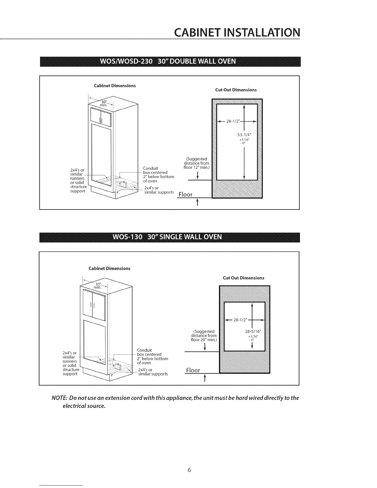
2) After creating your precision cabinet cutout and support and making power supply connection
as specified in this guide, with the oven in front of the cutout, slide the unit carefully into the
cabinet opening.
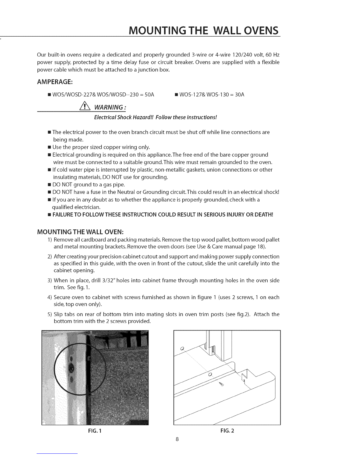
3) When in place, drill 3/32" holes into cabinet frame through mounting holes in the oven side
trim. See fig. 1.
4) Secure oven to cabinet with screws furnished as shown in figure 1 (uses 2 screws, 1 on each
side, top oven only).
5) Slip tabs on rear of bottom trim into mating slots in oven trim posts (see fig.2). Attach the
bottom trim with the 2 screws provided.
FIG. 1 FIG. 2

SERVICE
HOW TO OBTAIN SERVICE:
For warranty service, contact your local DCS authorized service agency. Provide him/her with the
Model Number, Serial Number, and date of installation, and a brief description of the problem. If you
need assistance in locating the authorized service agency in your area please contact our DCS
Customer Service Representative for an authorized service agent near you, our number is
(888) 281-.5698, Monday thru Friday, 6:00 am - 4:30 pm PST.
Your satisfaction is of the utmost importance to us. If a problem cannot be resolved to your
satisfaction, please write or email us at:
Write:
DCS
Attention: Customer Service
5800 Skylab Road
Huntington Beach, CA 92647
BEFORE YOU CALL FOR SERVICE:
1. Is the circuit breaker tripped or the fuse blown?
2. Is there a power outage in the area?
3. Have you recently set the child safety mode? See page 17 for resetting in the Use and Care
Guide.
9

WARRANTY
LENGTH OF WARRANTY
One (1) Year Full parts and Labor Covers the entire product.
Ten (10)Years Limited Porcelain oven, porcelain inner door panel.
DCS WILL PAY FOR
All repair labor and parts found to be defective due to materials or workmanship for one full year "IN
HOME" warranty from date of purchase. This does not apply if the unit was subjected to other than
normal household use. Service must be provided by Authorized Factory Technician during normal
working hours. No charges will be made for repair or replacement at the location of initial installation
or factory for parts returned pre-paid, through the dealer and claimed within the warranty period, and
found by DCS to be defective.
Replacement will be F.O.B.DCS, and DCS will not be liable for any transportation costs, labor costs, or
export duties. This warranty shall not apply, nor can we assume responsibility for damage that might
result from failure to follow manufactures instructions or local codes, where the appliance has been
tampered with or altered in anyway or which, in our judgement, has been subjected to misuse,
negligence, or accident.
DCS WILL NOT PAY FOR
[] Installation or start-up.
[] Shipping damage.
[] Service by an unauthorized agency.
[] Damage or repairs due to service by an unauthorized agency or the use of unauthorized parts.
[] Service during other than normal working hours.
[] Improper installation, such as improper hook-up, etc.
[] Service visits to teach you how to use the appliance; correct the installation; reset circuit
breakers or replace home fuses.
[] Repairs due to other than normal household use.
[] Damage caused from accident, abuse, alteration, misuse, incorrect installation or installation
not in accordance with local codes.
[] Units installed in non-residential application such as day care centers, bed and breakfast
centers, churches, nursing homes, restaurants, hotels, schools, etc.
This warranty applies to appliances used in residential applications; it does not cover their use in
commercial situations.
This warranty is for products purchased and retained in the 50 states of the U.S.A., the District of
Columbia and Canada. This warranty applies even if you should move during the warranty period.
Should the appliance be sold by the original purchaser during the warranty period, the new owner
continues to be protected until the expiration date of the original purchaser's warranty period.
This warranty gives you specific legal rights. You may also have other rights which vary from state to
state.
This warranty is in lieu of all other warranties, express or implied, and all implied warranties, induding
warranties of merchantability and fitness for a particular purpose, are hereby disclaimed to the full
extent permitted by law. Tothe extent that implied warranties may not be disdaimed, the duration of
any implied warranties, including implied warranties of merchantability and fitness for a particular
purpose, are limited to the duration of this express warranty. This warranty gives you specific legal
rights. You may also have other rights which vary from state to state.
10

PERFECT hEAT°
FOUR MURAL
Guide d'installation
MOD_=LES :
W0S-227
W0S-230
WOSD-227
WOSD-230 WOS-'I27
W0S-130 ®

A L'INTENTION DE NOS CLIENTS
Nous vousremercionsd'avoir choisi cefour mural professionnelDCS.Nous avonscon_uceManuel d'instal-
lation pour expliquer sesfonctions uniques. II contient des informations extr_mement utiles sur la fa¢on
d'installer correctement votre nouvel appareiL Vouspourrez ainsi enprofiter pendant desann_esen toute
s_curit_.
Si vous avez des questions au sujet de notre produit, communiquez avec un repr_sentant du Centre de
service _la clientele DCS par t_l_phone : 1-888-281-5598, du lundi au vendredi, de 5 h _15 h 30, heure
ou par courtier:
DCS
Attention: CustomerService
5800 SkylabRoad
Huntington Beach,CA92547
AVERTISSEMENT
Toute installation, ajustement, alteration ou entretien incorrect peut causer des
dommages materiels, des blessures ou la mort. Veuillez fire soigneusement ces
instructions d'installation, d'utilisation et d'entretien avant d'utiliser, instafler
ou effectuer I'entretien de cet appareiL
/k
AVERTISSEMENT
Evitez de stocker ou d'utiliser de I'essence ou tous autres fiquides et vapeurs
inflammables _proximit_ de cet appareil ou de tout autre appareil
_lectrom_nager.
AVERTISSEMENT RELATIF A LA SECURITE :
Coupez le circuit #lectrique au niveau du panneau de service et
verrouillez le panneau avant de brancher cet appareil #lectrom#nager.
Alimentation : Circuit de branchement de 120/240 V c.a., 50 Hz, 50 A
4 fiL
AVERTISSEMENT
NE VERSEZPASd'eau sur les feux de graisse. Eteignez le four mural, puis
#touffez le feu avec du bicarbonate de soude ou a I'aide d'un extincteur
poudre ou a mousse.
VEUILLEZ CONSERVER CE MANUEL A TITRE DE ReFeRENCE.

TABLE DES MATIERES
DIMENSIONS DU FOUR MURAL
Fours doubles WOS-227 27 po ...........................................................................................................................3
Fours simples WOS-127 27 po ............................................................................................................................3
Fours doubles WOS-230 30 po ...........................................................................................................................4
Fours simples WOS-130 30 po ............................................................................................................................4
INSTALLATION EN ARMOIRE
Fours doubles WOS/WOSD-227 27 po ............................................................................................................5
Fours simples WOS-127 27 po ............................................................................................................................5
Fours doubles WOS/WOSD-230 30 po ............................................................................................................6
Fours simples WOS-130 30 po ............................................................................................................................6
INSTALLATION SOUS COMPTOIR
Fours simples WOS-127 et 130 ...........................................................................................................................7
MONTAGE DU FOUR MURAL .............................................................................................................8
POUR L'OBTENTION DE SERVICE .....................................................................................................9
GARANTIE ....................................................................................................................................................................10-I 1

DIMENSIONS DU FOUR MURAL
68 cm
T
66 crr I
\/
Vis de garniture inf6rieure
--- 56 cm _1
I_€ °_m_1
-- /
136cm
130cm
Dimensions int_rieures (H x I x p) = 40,6 x 55,9 x 47,3 cm
Dimensions de grille (I x p) = 54,3 x 38,1 cm
68 cm
73 cm
\/
Vis de garniture inf_rieure
(13
56 cm _
2 cm
0 cm-----_
'qJ__
t
4cm
67 cm
Dimensions int_rieures (H x I x p) = 40,6 x 55,9 x 47,3 cm
Dimensions de grille (I x p) = 54,3 x 38,1 cm

DIMENSIONS DU FOUR MURAL
_------- 76 cm
C
66 cm [
\/
Vis de garniture inf6rieure
136cm
_-...--56 cm -......._I
i_po cm----_1
-- /
130cm
Dimensions int6rieures (H x I x p) = 40,6 x 55,9 x 47,3 cm
Dimensions de grille (Ix p) = 62 x 38,1 cm
_---------- 76 cm
C D
73 cm
\/
Vis de garniture inf6rieure
CI3
_6 56 cm---_
4cm
67 cm
Dimensions int6rieures (H x I x p) = 40,6 x 55,9 x 47,3 cm
Dimensions de grille (I x p) = 62 x 38,1 cm
4

INSTALLATION ENARMOIRE
Nos fours sont con_us pour _tre install_s dans une armoire d'une largeur minimum de 68,6 et 76,2 cm
(27 et 30 po). Pour donner une belle apparence _ l'appareil, les d_coupes doivent _tre pr_cises afin d'en
dissimuler les bords bruts et de permettre un ajustement serr_ et solide. Utilisez les dimensions de
d_coupe pour four mural fournies pour votre installation. Comme les fours sont tr&s lourds, nous
sugg_rons que deux installateurs se chargent de les soulever et les placer dans l'ouverture de l'armoire.
[] Coupez des pi&ces d'appui 2x 4 ou construisez une 6tag&re solide pouvant supporter le four au
fond.
[] Le support inf_rieur doit _tre de niveau et capable de supporter le poids du four -
(c.-_-d. 202 kg/445 livres - four double ou 125 kg/275 livres - four simple).
[] Le c_ble _lectrique doit comporter un fil _ 3 ou 4 conducteurs conform_ment _ la
r_glementation en vigueur (doit _tre c_bl_ et d_di_).
[] Raccord de conduit homologu_ UL requis.
[] La boke de raccordement doit _tre situ_e au centre sous le four, _ 5 cm (2 pouces) en dessous de
sa pattie inf_rieure.
[] Le c_blage d'alimentation doit _tre connect_ avant I'installation du four dans I'armoire.
Dimensions de I'armoire
structure
Dimensions de d_coupe
(Distance
sugg_r_e
partir du
Boite de plancher 30,5
raccordement cm/12 po min.)
centr_e 5 cm (2 po)
en dessous de la _
partie inferieure
du four
2x4 ou
supports
similaires Plancher
Dimensions de I'armoire
2x4 ou
c_i_ces
'appui
similaires
ou support
solide de
structure
/
!Boite de
raccordement
centr6e 5 cm (2 po)
en dessous de la
c_artie inf6rieure
u four
2x4 ou
(Distance
sugg6r6e
partir du
plancher 50,8
cm/20 po min.)
+
Planchert
Dimensions de d_coupe

INSTALLATION ENARMOIRE
Dimensions de I'armoire
I li II I Boite de grg_irdu
Ili I1_ I raccordement , p ....
• plancner _U b
I li Ili I centreeScm(2po) cm,12_omi'n,
2x4ou I Ii II] I endessousdela -w .,
pieces _ ILL_ partieinf6rieure I
d'appui I L _ l_ ..... I du four _F
similaires _r_:L!._
ou support-}'_ _ I_I_ 2x4ou
solidede L._ -'---_IJS _J-- supports
structure _ similaires Plancher
t
Dimensions de d_coupe
Dimensions de I'armoire
Dimensions de d_coupe
2x4 ou
c_ieces
'appui
sirnilaire__
ou suppor
solide de
structure
Boite de
raccordement
centr6e 5 cm (2 po)
en dessous de la
pattie inf6rieure
du four
2x4 ou
(Distance
sugg6r6e
partir du
plancher 30,5
cm/12 po min.)
Plancher
t
REMARQUE :N'utifisez pas de rallonge avec cet appareiL Celui-ci dolt @tre c_bl@directement a la
source @lectrique.
6

INSTALLATION SOUS COMPTOIR AVEC CT-365
FOURS SIMPLES W0S-127 ET 130
Les fours simples WOS-127 et WOS-130 peuvent 6tre install_s sous la table de cuisson _ gaz DCS CTR-365
dans un placard sur plancher standard de 36 po de haut (jusqu'_ la surface du comptoir). Reportez-vous au
sch6ma ci-dessous concernant les dimensions de d6coupe du placard sur plancher et du comptoir.
Le robinet d'arr6t de I'alimentation de gazet le bloc d'alimentation de la table de cuisson doivent rester
accessibles par I'avant une lois les appareils install_s. Nous vous conseillons de les placer dans le placard
adjacent au four mural sur la droite. Pour 6viter route interference avec le chassis du four mural, installez le
r6gulateur de gaz de la table de cuisson au niveau du robinet d'arr6t. Effectuez la connexion entre le
r6gulateur et la table de cuisson _ I'aide d'un tuyau _ gaz flexible homologu6.
Installez la table de cuisson sur le comptoir en premier. Effectuez les raccords au gaz et au dispositif
d'alimentation conform6ment aux instructions d'installation de la table de cuisson. V6riflez que I'alimen-
ration 61ectfique du four est coup6e. Effectuez les connexions d'alimentation du four mural, puis glissez
I'appareil dans le placard. Fixez I'appareil au placard tel qu'indiqu6 dans la section <<Montage du four
mural _.Activez routes les sources d'alimentation et v6rifiez le bon fonctionnement de chaque appareil.
AVERTISSEMENT :
Lorsque vous enfoncez le four mural clans le placard, faites attention de ne pas
pincer la connexion b gaz de la table de cuisson.
Face d'armoire
-4
3,8 cm
Min,
71,9 cm
+1,5 mm
-0
50,2 cm
88,3 cm
91,4 cm
61 cm

MONTAGE DESFOURS MURAUX
Nos fours encastr_s n_cessitent une alimentation _lectrique d_di_e et correctement mise _ la terre _ 3 ou 4
fils de 120/240 V,60 Hz protegee par un fusible ou disjoncteur temporis_. Les fours sont fournis avec un
c_ble d'alimentation flexible qui dolt &tre branch_ _ une bo_te de jonction.
INTENSITE :
[] WOS/WOSD-227 et WOS/WOSD-230 = 50A [] WOS-127 et WOS-130 = 30A
/_ AVERTISSEMENT :
Risque de choc _lectrique!! Suivez les instructions ci-dessous!
[] Coupez le courant _lectrique alimentant le circuit de branchement du four pendant que vous
effectuez routes les connexions.
[] Utilisez uniquement un c_blage de cuivre de diam&tre appropri_.
[] Cet appareil _lectrom_nager n_cessite une mise _ la terre _lectrique. L'extr_mit_ libre du fil de terre
en cuivre nu doit &tre connect_e _ une terre ad_quate.Ce fil doit rester mis _ la terre sur le four.
[] I_VITEZd'utiliser le tuyau d'eau froide comme prise de terre s'il est interrompu par des joints non
m_talliques en plastique, des connexions-unions ou d'autres mat_riaux isolants.
[] N'UTILISEZ PASle tuyau de gaz comme prise de terre.
[] NE PLACEZ PAS de fusible dans le circuit neutre ou de terre. Cela pourrait provoquer un choc
_lectrique!
[] Consultez un _lectricien qualifi_ si vous avez des doutes concernant la mise _ la terre de I'appareiL
[] LE FAIT DE NleGLIGER CES INSTRUCTIONS PEUT ENTRA|NER DES BLESSURESGRAVES OU MItME
LA MORT!
MONTAGE DU FOUR MURAL :
1) Retirez tousles cartons et le materiel d'emballage. Retirez la palette de bois sup_rieure et inf_rieure,
et les supports de montage m_talliques. Retirez les portes du four (voir le manuel d'utilisation et
d'entretien _ la page 18).
2) Apr&s avoir cr_ de fa(_on precise la d_coupe et le support de I'armoire et effectu_ les connexions
d'alimentation tel que sp_cifi_ dans ce manuel, placez le four devant la d_coupe puis glissez
I'appareil soigneusement dans I'ouverture de I'armoire.
3) Une lois l'appareil en place, percez des trous de 2,4 mm (3/32 po) dans le cadre de l'armoire _ travers
les trous de montage de la garniture lat6rale du four.Voir fig. I.
4) Fixez le four _ I'armoire _ I'aide des vis fournies tel qu'indiqu_ _ la figure 1 (utilisez 2 vis, 1de chaque
c6t_, sur four du haut seulement).
5) Glissez les languettes _ I'arri&re de la garniture inf_rieure dans les fentes correspondantes des tiges
de la garniture du four (voir fig. 2).Fixez la garniture inf_rieure _ I'aide des 2 vis fournies.
8
This manual suits for next models
5
Table of contents
Languages:
Other DCS Oven manuals