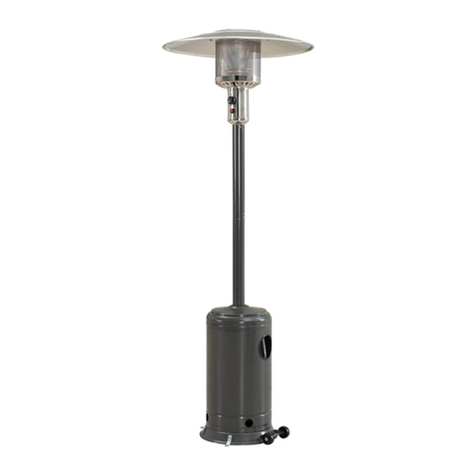
DCS PHFS-P4 Installation guide

1
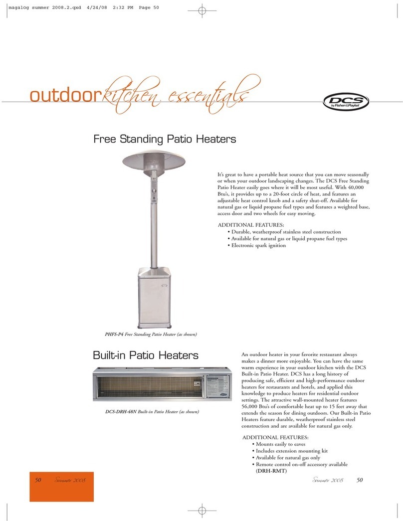
THE FREE STANDING PATIO HEATER
Use and Care and Installation Guide
MODEL:
PHFS-P4


1
Thank you for selecting the DCS Patio Heater by Fisher & Paykel. Because of this appliance’s unique features we
have developed this Use & Care and Installation Guide. It contains valuable information on assembly instructions
and how to properly operate and maintain your new appliance for years of safe and enjoyable use.
To help serve you better, please fill out and submit your Product Registration by visiting our website at
www.dcsappliances.com and selecting “Customer Care” on the home page, then select “Product Registration”. In
addition, keep this guide handy, as it will help answer questions that may arise as you assemble and use your
new appliance.
For your convenience, product questions can be answered by a DCS Customer Care Representative by phone:
NOTE:Inspect the product to verify that there is no shipping damage. If any damage is detected, call the shipper
and initiate a damage claim. DCS by Fisher & Paykel is not responsible for shipping damage.
DO NOTdiscardany packing material (box, pallet, straps) until the unit has been inspected.
WARNING!
Improper installation, adjustment, alteration, service or maintenance can cause property damage,
injury or death. Read the installation, operating and maintenance instructions thoroughly before
installing, using or servicing this equipment.
WARNING!
Ifthe information in this manual is not followed exactly, a fire or explosion may result causing
property damage, personal injury or death.
WARNING
Do not store or use gasoline or other flammable vapors and liquids in the vicinity of this or any other
appliance. An LP cylinder not connected for use shall not be stored in the vicinity of this or any other
appliance.
DANGER
IfYou Smell Gas:
1. Shut off gas tothe appliance.
2. Extinguish any open flames.
3. If odor continues, immediately call your gas supplier or your fire department.
WARNING! For outdoor use only
WARNING!
Do not trylighting this appliance without reading the “Lighting Instructions” section of this manual.
This outdoor gas appliance is not intended to be installed in or on recreational vehicles , boats or in a
non-ventilated room. For outdoor use only.
AMESSAGE TO OUR CUSTOMER
PLEASE RETAIN THIS MANUAL FOR FUTURE REFERENCE.
NOTE: Please write the Model, Code, and Serial Numbers on this page for reference (can be found on the right
side of the cabinet interior).
MODEL NUMBER CODE SERIAL NUMBER

2
SAFETY PRACTICES AND PRECAUTIONS 3
RECOMMENDATIONS ON HOOKUP TO GAS SUPPLY
Natural Gas Hookup 4
LP Gas Hookup 4
FEATURES 5
ASSEMBLY TOOLS & FASTENERS 6
ASSEMBLY INSTRUCTIONS 7-10
GAS LEAK TEST 11
LOCATING HEATER FOR USE 12
LIGHTING AND SHUTDOWN
LP Operation 13
Natural Gas Operation 14
STORAGE AND INSECT WARNING 15
TROUBLESHOOTING 16-17
SERVICE 18
WARRANTY 19-20
CONTENTS

3
■
Read and become familiar with the entire manual.
■
Do not use in an explosive atmosphere, keep heater away from areas where gasoline or other flammable liquids
or vapors are stored or used.
■
Before each use, check for damaged parts such as hoses, regulators, pilot or burner.
■
Do not attempt to alter unit in any manner, ie: shorten post length, bypass safety valve or operate heater without
the reflector.
■
Heater must always be placed on a hard and level surface.
■
Always maintain proper clearance to combustible materials. (Top =19’’; sides and rear =27”), see page 12.
■
Never replace or substitute the regulator with any other regulator other than a factory suggested replacement.
■
Itis imperative that the control compartment, burners, and circulating air passageways of the heater be kept
clean. The heater should be inspected before each use, and at least annually by a qualified service person, for
the presence of spiders, webs or other insects. The burner area is a common and desired spider haven. Spider
webs can present a dangerous condition which can damage the heater and render it unsafe for use.
CHECK THE HEATER IMMEDIATELY IF ANY OF THE FOLLOWING CONDITIONS EXIST
1. The smell of gas in conjunction with extreme yellow tipping of the burner flames.
2. The heater does not reach temperature.
3. The heater glow is excessively uneven.
4. The burner makes popping noises during use (a slight popping noise is normal when the burner is extinguished).
■
Installation must be carried out in accordancewith local regulations in force.
■
Do not clean heater with combustible or corrosive cleaners.
■
Do not use if wind velocity is greater than 10 miles per hour, because of flame-out possibility.
■
To avoid the risk of burns or accidental clothing ignition, do not touch the heater anywhere near the burner
assembly during operation.
■
Donot touch the burner assembly or reflector shield until after the heater has cooled for a minimum of 20 min-
utes after use.
■
Carefully monitor young children in the vicinity of the heater, especially when it is in operation.
■
Never connect an unregulated gas supply.
■
Always ensure that there is ample fresh air ventilation. This unit is for outdoor use only.
■
CALIFORNIA PROPOSITION 65-WARNING: The Burning of gas cooking fuel generates some by-products which
are on the list of substances which are known by the State of California to cause cancer or reproductive harm.
California law requires businesses to warn customers of potential exposure to such substances. To minimize
exposure tothese substances, always operate this unit according to the Use and Care Guide, ensuring you
provide good ventilation when cooking with gas.
■
This outdoor appliance is not intended to be installed in or on recreational vehicles and/or boats.
SAFETY PRACTICES & PRECAUTIONS

4
NATURAL GAS HOOKUP
The gas supply connections should be made by a qualified technician and in
accordance with local codes or ordinances. In the absence of a local code, the
installation must conform to the latest edition of National Fuel Gas Code
ANSI 223.1.
Amanual shut-off valve must be installed external to the appliance, in an
accessible location from the front for the purpose of shutting off the gas
supply (Fig.01). Any excess internal supply line must not protrude beyond the
back of the unit. Make sure the gas supply is turned off at the wall valve
before connecting the appliance. Make regulator connection as close to the
internal flex tube as possible. If the natural gas heater is intended to be
mobile, we recommend using a strain relief cord to ensure the gas line will not
be stressed.
Note:
This product must be installed by a licensed plumber or gas fitter when installed within the Commonwealth of
Massachusetts.
LP GAS HOOKUP
The heater comes equipped with a regulator/hose assembly for connection to a standard Type 1 valve with an
OPD 20 lb. / 5 gallon LP gas tank (not included) and 2 straps to secure the tank within the base. A dented or
rustyLPtank maybe hazardous and should be checked by your LP supplier.
Never use an LP tank with a damaged valve. The LP tank must be arranged to provide for vapor withdrawal from
the operating cylinder.
The heater is designed tohouse a 20 lb./5gallon gas cylinder in the base assembly. Never connect an unregu-
lated LP tank to the heater. Never substitute gases without first converting the heater with a factory supplied
conversion kit. Conversion kits areavailable through customer service and must be installed by a qualified tech-
nician.
TOCONNECT LP CYLINDER TO THE HEATER
Open the door,and connect LP regulator assembly to the tank valve. The regulator and the tank have right-
handed threads (clockwise to tighten; no pipe sealer or teflon tape is required). When tightening, be careful not
to put too much force on the cylinder valve. Place the cylinder into the housing.
RECOMMENDATIONS ON HOOKUP TO GAS SUPPLY
A. Connect LP regulator assembly to the tank valve (Fig. 02).
B. Check regulator connections to the LP tank and to the flex tube for leaks. Tighten connections if necessary.
Place tank into the cabinet. Fix the tank position using two straps (Fig.03).
Gas Hook-up with shut-off valve
FIG. 01
FIG. 02 FIG. 03

5
■
Weather Resistant
■
All High Heat Parts Made Of Stainless Steel
■
Uniform Heat Pattern
■
Flame Out Protection Safety Control Valve
■
Durable Non-Slip Wheels
■
Weighted Base For Stability
■
Low Maintenance
■
Electronic Spark Ignition
■
Easy Access Door With Positive Latch
■
Heats 16’-20’ Diameter Area
■
Large Stainless Steel Emitter Grid
■
Uses 5 Gallon 20 lbs. LP Tank (not included)
■
Models Available For Natural Gas Or LP; Field Convertible
■
40,000 Btu Burner
FEATURES

6
ASSEMBLY TOOLS & FASTENERS
Tools Required:
PATIO HEATER COMPONENTS
PICTORIAL DESCRIPTION QTY
Reflector 1
Post 1
Head Assembly 1
Cabinet 1
Knob 1
Rubber Ring 1
Ring, Reflector 1
Retainer Bracket 1
FlatWasher 2
Tank Strap 2
LP Regulator (LP Heater only )
(connected) 1
Natural Gas Regulator
(Nat. Heater only) 1
Hex Screw 1/4 - 20 x 3/4” 6
Split Washer 1/4” 3
Button Head Screw 1/4 - 20 x
1/2” 3
Use & Care & Installation
Manual 1
Wrench or Socket 7/16”(1 pc),
3/4”(1 pc), 7/8” (1 pc)
5/32” Allen Wrench (1 pc)
Power Screwdriver or
Variable Speed Drill with
Phillips -tip #2 Attachment
Gloves

7
ASSEMBLY INSTRUCTIONS
CAUTION:
Some parts have sharp edges; care must be taken when handling the various components to avoid injury. Please
read safety information provided in these instructions before beginning assembly. Wear gloves when handling.
STEP 1 POST INSTALLATION
A. Insert post into the cabinet top. The threaded
hole should be oriented toward the front (door).
B. Install rubber ring (F) over the post.
STEP 2 INSTALLING THE PATIO HEATER
HEAD
A. Remove four #10 screws holding the valve
panel using Phillips screwdriver and set them
aside.
B. To get access to ignition wires, disengage (gently
pull on wires) the valve panel and head body. Dis-
connect ignition wires from igniter, remove valve
panel.

8
C. Straighten the flex tube. Insert regulator and
flex tube into the post. Slide patio heater head
over the post. Align 3 head holes with thread-
ed post holes.
D. Attach patio heater head to the post using
3button head screws (P) with 5/32” Allen
wrench.
ASSEMBLY INSTRUCTIONS
E. Attach the post to the cabinet using bracket (H),
and Hex screw 1/4-20 x 3/4 (M). Add two more
Hex screws 1/4-20 x 3/4 (M), and two Flat washer
0.313 (I) on each side of the sleeve. Slide flex hose
into center of retainer bracket. Ensure the post is
vertical before tightening the screws.

9
ASSEMBLY INSTRUCTIONS
F. Reattach 2 wires to the ignition module.
G. Install valve panel and attach it to the head
using 4 screws with a Phillips screwdriver.
H. Install the valve knob (E).

10
ASSEMBLY INSTRUCTIONS
STEP 3 REFLECTOR INSTALLATION
A. Place the reflector on to the patio heater
head and attach it using reflector ring (G),
three 1/4 - 20 x 3/4” screws (M), three split
washers (N) with 7/16” open wrench.
STEP 4 CONNECTING REGULATOR
ASSEMBLY (LP ONLY)
A. Ensure the hose of the regulator assembly is
inside the retainer bracket in the cabinet.
B. Attach two tank straps (J) to the cabinet rear
bracket.

11
PRECAUTIONS
■
Periodically check the entire gas system for leaks or check immediately
ifthe smell of gas is detected.
■
Extinguish all open flames.
■
Never leak test while smoking. If you cannot stop a leak, turn off
the cylinder valve and call the dealer you purchased the heater
from or Customer Care at 1-888-936-7872.
■
Do not use heater until all connections have been leak
tested and do not leak.
■
When leak testing, refer to the connections diagrams,
Figures 04 and 05.
■
Only those parts recommended by the manufacturer should be
used.
■
Substitution of parts can void warranty.
LEAK TEST
Make a soap solution of one partliquid detergent, and one part
water. The soap solution can be applied with a spray bottle, brush
or rag. Soap bubbles will appear wherealeak is present. Make sure
the safety valve control knob is in the “OFF” position. Turn the gas
supply on, check for leaks at leak point. If a leak is present, turn off
supply,tighten anyleaking fittings,turn gas on and recheck.
CHECK THE FOLLOWING CONNECTIONS (FIG. 04, 05)
1. Regulator togas cylinder.
2. All connections on the hose/regulator assembly.
3. The reducer fitting and the intake pipe.
Note:
To leak test the following connections, remove the valve panel as shown
in Step 2, page 8.
4. Flex tube connection to the fitting.
5. Fitting connection to the safety valve .
6. Pilot tubing to pilot.
7. Pilot tubing to the safety valve.
8. Orifice extension to the safety valve.
9. Orificeto the orifice extension.
Once leak tested, replace the valve panel as shown on page 9.
Note:
Gas connections on the heater head assembly are leak tested at the
factory prior to shipment.
GAS LEAK TEST
FIG. 05
FIG. 04
2
13
5
6
7
4
8
9

12
This outdoor heater is used primarily for temporary heating of outdoor patios, decks, spas, pools, and work areas.
This heater is not intended for indoor use or in an enclosed area. Always ensure that adequate fresh air ventila-
tion is provided.
CAUTION!
The heater must be placed on level, firm ground. Heater wheels will engage the ground and start to roll once a
minimum angle from center is established.
WARNING!
Never operate in an explosive atmosphere. Keep away from areas where gasoline or other flammable liquids or
vapors are stored or used.
Maintain 19” minimum clearance above the heater reflector to combustible (see definition below) construction.
Maintain 27” minimum horizontal clearance from the edge of reflector to combustible construction, all around
the unit (Fig. 06).
The installation must conform to local codes, or in the absence of local codes, with the standard for the storage
and handling of liquefied petroleum gases, ANSI/NFPA 58-1986.
DEFINITION OF COMBUSTIBLE MATERIAL - Materials made of or surface with wood, compressed paper, plant fibers, or
other materials that are capable of being ignited and burned. Such material shall be considered combustible even
though flame-proofed, fire-retardant treated, or plastered.
WARNING!
Ifanoncombustible material such as stucco is covering a combustible material such as wood, the minimum clear-
ance distance needs to be held to the wood. The presence of a noncombustible material inside the clearance zone
does not eliminate the minimum clearance zone to combustible material.
DEFINITION OF NONCOMBUSTIBLE MATERIAL - Material which is not capable of being ignited and burned, such as mate-
rials consisting entirely of, or a combination of, steel, iron, brick tile, concrete, slate, and plaster.
WARNING!
The Free Standing Patio Heater is designed to function in an open area. Recommended minimum clearances should
be maintained toall surfaces (combustible and noncombustible) for optimum performance. Noncombustible materi-
al within the minimum clearancearea could result in discoloration or deterioration.
LOCATING HEATER FOR USE
FIG. 06
27” min.
19” min.
COMBUSTIBLE
COMBUSTIBLE
COMBUSTIBLE
27” min.

13
LP OPERATION
Before turning the gas supply “ON”
Make sure regulator hose is connected to the heater intake pipe and regulator is connected to the LP tank with
both connections tight and leakproof.
Visually inspect the hose assembly for evidence of excessive abrasion, cuts or wear. If the hose leaks, it must be
replaced prior to use. The replacement hose assembly shall be that specified by the manufacturer. Make sure the
surrounding areas are free of combustible materials, gasoline and other flammable vapors or liquids.
Before lighting
For your safety, if relighting a hot heater, always wait 5 minutes. The heater should be inspected (emitter screen,
gas hookup, pilot assembly) before each use, and at least annually by a qualified service person.
To light:
1. Open door. Ensure the control knob is in the “OFF” position.
2. Turn supply tank valve in a counter-clockwise direction. Open valve fully. Check for leaks by applying soapy water
to the tank and hose connections.
3. The pilot is located behind the match hole cover. Rotate the disc upward from the hole for match lighting or
viewing.
4. Turn control knob counter-clockwise to the pilot position.
5. For regular relight, depress and hold in the control knob for 5 seconds to begin pilot gas flow. On new installa-
tions or cylinder changes to purge air from the lines, hold in the control knob for (3) minutes.
6. While depressing knob,depress the electronic igniter button, which will produce a spark that will light the pilot.
7. Once the pilot is lit, continue to hold in the control knob for 30 seconds or until the pilot remains lit after knob is
released.
8. The burner may now be turned to the full “HI” position. Reduce to the desired heat range.
9. Close door.
Relighting:
1. Turn control knob to off position.
2. Wait (5) minutes before attempting to relight a hot heater pilot.
3. Repeat steps beginning with step (4) above.
Shut down instructions:
1. Turn control knob clockwise to the “OFF” position. The burner will make a slight popping sound when extin-
guished. This is a normal condition.
2. Turn LP-tank gas valve clockwise to “OFF” position when heater is not in use.
LIGHTING AND SHUT DOWN

14
NATURAL GAS OPERATION
Before turning the gas supply “ON”
Make sure the natural gas line is connected to the heater through the regulator, supplied by the manufacturer,
and all connections are free of damage, tightened and leak proof.
Before lighting
For your safety, if relighting a hot heater, always wait 5 minutes. The heater should be inspected (emitter screen,
gas hookup, pilot assembly) before each use, and at least annually by a qualified service person.
To light:
1. Open door. Ensure the control knob is in the “OFF” position
2. Turn the gas shut-off valve to the “ON” position.
3. Turn control knob counter-clockwise to the pilot position.
4. The pilot is located behind the match hole cover. Rotate the disc upward from the hole for match lighting or
viewing.
5. For regular relight, depress and hold in the control knob for 5 seconds to begin pilot gas flow. On new installa-
tions or cylinder changes topurge air from the lines, hold in the control knob for (3) minutes.
6. While depressing knob, depress the electronic igniter button, which will produce a spark that will light the pilot.
7. Once the pilot is lit, continue to hold in the control knob for 30 seconds or until the pilot remains lit after knob is
released.
8. The burner may now be turned to the full “HI” position. Reduce to the desired heat range.
9. Close door.
Relighting:
1. Turncontrol knob to off position.
2. Wait (5) minutes before attempting to relight a hot heater pilot.
3. Repeat steps beginning with step (5) above.
Shut down instructions:
1. Turn control knob clockwise to the “OFF” position. The burner will make a slight popping sound when extin-
guished.This is a normal condition.
2. Turn gas shut-off valve to the “OFF” position.
LIGHTING AND SHUT DOWN

15
Note:
When storing the heater, the connection between the LP cylinder and the heater must be disconnected and the LP cylin-
der removed and stored outdoors in a well ventilated area.
SPIDER & INSECT WARNING!
Spiders or insects can nest in the burners or orifices of this or any outdoor gas appliance. This is a very dangerous
condition which can damage the heater and render it unsafe for use. You must inspect the burner at least once a
year or immediately if any of the following conditions occur:
1. The smell of gas in conjunction with extreme yellow tipping of burner flame.
2. The heater does not reach temperature.
3. The heater glow is excessively uneven.
4. The burner makes popping noises.
Ifblockage exists, call Customer Care (888) 936-7872.
STORAGE AND INSECT WARNING

16
Can you match light the
pilot?
Problem:
Pilot does not light
using the spark
igniter
YES
NO
Spark igniter problem. Is there a spark at the pilot
when the button is pressed?
Is there adequate gas supply
available?
YES
NO
See lighting
instructions.
Remove valve panel, make sure
igniter wireis attached tospark
igniter. Ensureother output of
spark igniter is grounded to
inside of the valve panel.
NO
Has the igniter wire insulation been
pinched,cut,or burnt away?
YES NO
Call customer
carefor
replacement pilot
assembly
or
replacement wiring.
Replacespark
igniter. Call
customer service
for
replacement.
YES NO
Is supply hose bent
or kinked?
Is gas cylinder full?
Are lighting
instructions being
followed?
Straighten
hose. Check for
leaks.
YES
NO
Check pilot for
blockage.
YES
NO
Replace battery.
TROUBLESHOOTING

17
TROUBLESHOOTING
Is there adequate
gas supply?
Problem:
Burner flame is
low.
YES
Fill LP cylinder NO
Is the supply hose bent or kinked?
Straighten hose
YES
Is the control knob in the full “on”
position? (all the way counter -
clockwise)?
Is there adequate
gas supply?
Problem:
Emitter glow is
uneven.
Note:
It is normal for the bottom 1/2”to 1”of the emitter not to glow.
In addition, the section of the emitter above the valve panel may
also glow less than the rest of the emitter.
YES
Is the heater level? Fill LP cylinder
NO
YES
Is the lower screen cone tilted?
When cool,loosen but don’t remove screws at
top of safety valve cylinder, level, retighten.
Attach the screen to the bottom cone.
Level heater
Call Customer Care
NO
NO
NO
YES

18
HOW TO OBTAIN SERVICE:
For warranty service, contact DCS Customer Care at (888) 936-7872. Before you call, please have the
following information ready:
■
Model Number (can be found on the right side of the cabinet interior).
■
Serial Number (can be found on the right side of the cabinet interior).
■
Code (can be found on the right side of the cabinet interior).
■
Date of installation
■
Abrief description of the problem
Your satisfaction is of the utmost importance to us. If a problem cannot be resolved to your satisfaction, please
Fisher & Paykel Appliances, Inc.
Attention: DCS Customer Care
5900 Skylab Road
Huntington Beach, CA 92647
SERVICE
Other manuals for PHFS-P4
1
Table of contents
Languages:
Other DCS Patio Heater manuals
Popular Patio Heater manuals by other brands

Endless Summer
Endless Summer EWTS830SP owner's manual

Nexgrill
Nexgrill T-007 Installation, operation and maintenance instructions

Backyard Pro
Backyard Pro Patio Series Operation instructions

Napoleon
Napoleon SRPH02-XXXX owner's manual

Firesense
Firesense LIP-10A-TGG owner's manual

Firesense
Firesense PH01-S XL Series instruction manual