DCS 50si Operating and maintenance instructions

CONTENTS

CONTENTS
Digital Communications System
General Description
Every effort has been made to eliminate errors and ambiguities in the information
contained in this guide. Any questions concerning information presented here should
be directed to SAMSUNG TELECOMMUNICATIONS AMERICA, INC., 2700 NW
87th Avenue, Miami, FL 33172, telephone (305) 592-2900. SAMSUNG
TELECOMMUNICATIONS AMERICA, INC. disclaims all liabilities for damages
arising from the erroneous interpretation or use of information presented in this
guide.

CONTENTS
telecommunications
Publication Information
SAMSUNG TELECOMMUNICATIONS AMERICA, INC. reserves the right without
prior notice to revise information in this publication for any reason.
SAMSUNG TELECOMMUNICATIONS AMERICA, INC. also reserves the right
without prior notice to make changes in design or components of equipment as
engineering and manufacturing may warrant.
Copyright 1998
Samsung Telecommunications America, Inc.
All rights reserved. No part of this manual may be reproduced in any form or by any
means—graphic, electronic or mechanical, including recording, taping, photocopying
or information retrieval systems—without express written permission of the publisher
of this material.
PRINTED IN USA 12/98

CONTENTSTABLE OF CONTENTS
PART DESCRIPTION PAGE
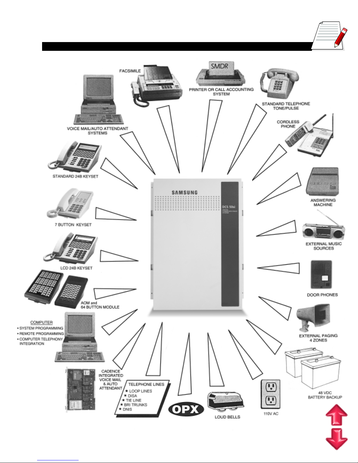
1SYSTEM OVERVIEW
1.1 SIZE AND CONFIGURATION ......................................................... 1.2
1.2 TECHNOLOGY ............................................................................... 1.4
1.3 PROGRAMMING ............................................................................ 1.5
2HARDWARE DESCRIPTIONS
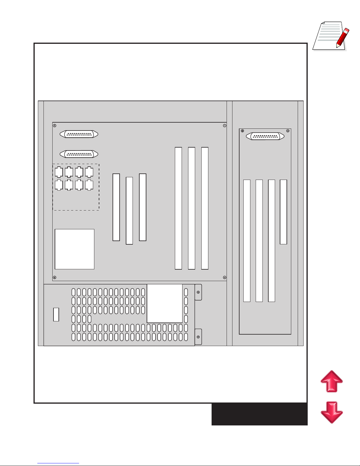
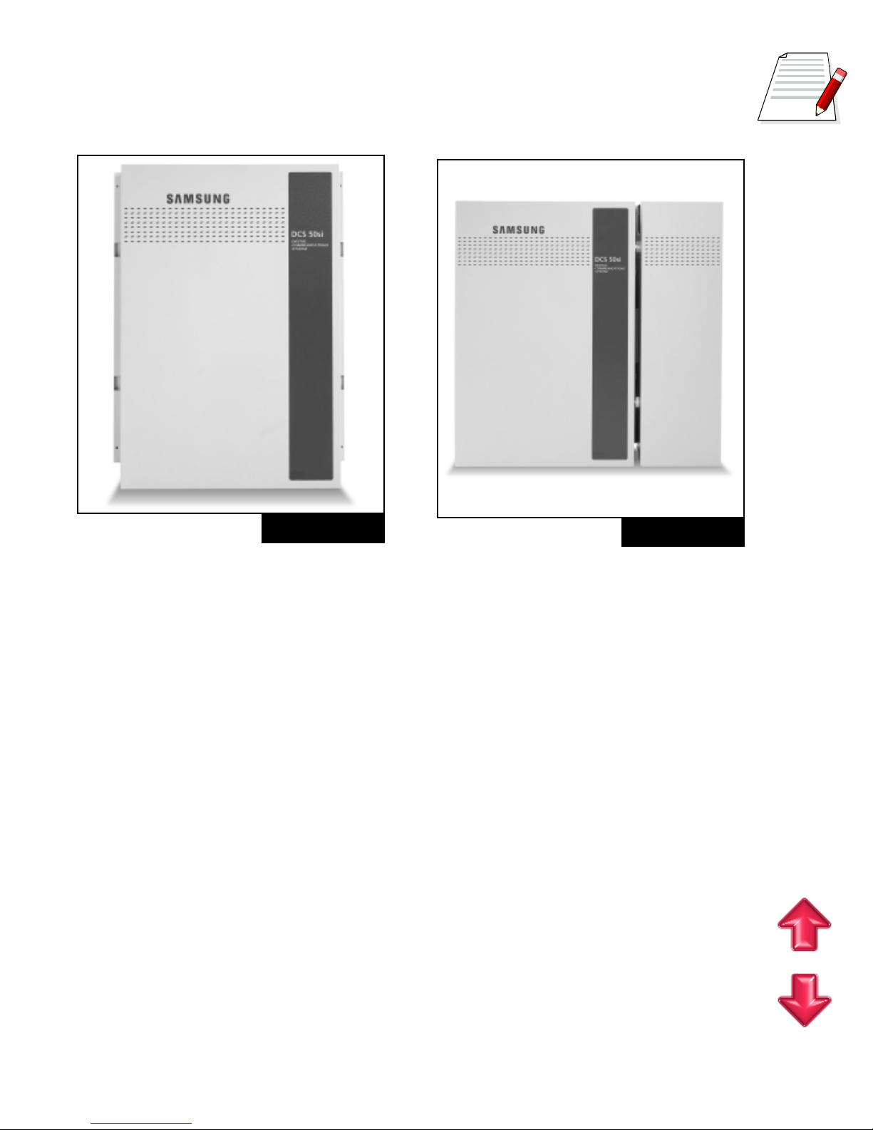
2.1 KEY SERVICE UNIT ....................................................................... 2.1
2.2 EXPANSION CABINET ................................................................... 2.1
2.3 SMEM2 CARD ................................................................................ 2.1
2.4 INTERFACE CARDS....................................................................... 2.2
2.5 STATION EQUIPMENT ................................................................... 2.5
3SPECIFICATIONS
3.1 ELECTRICAL SPECIFICATIONS ................................................... 3.1
3.2 DIMENSIONS AND WEIGHTS ....................................................... 3.1
3.3 ENVIRONMENTAL LIMITS ............................................................. 3.2
3.4 CABLE REQUIREMENTS............................................................... 3.2
3.5 SYSTEM TONES ............................................................................ 3.2
3.6 KEYSET LED INDICATIONS .......................................................... 3.4
3.7A RESERVE POWER DURATION ESTIMATES................................ 3.4
3.7B RESERVE POWER DURATION ESTIMATES
– WITH/WITHOUT CADENCE ....................................................... 3.5
4FEATURES
4.1 SYSTEM FEATURES................................................................... 4.1.1
4.2 STATION FEATURES .................................................................. 4.2.1
4.3 DISPLAY FEATURES .................................................................. 4.3.1
4.4 SAMPLE SMDR PRINTOUT ........................................................ 4.4.1
4.5 SAMPLE SMDR PRINTOUT WITH CALLER ID.......................... 4.5.1
4.6 SAMPLE UCD REPORT.............................................................. 4.6.1
4.7 CALL STATISTICS ....................................................................... 4.7.1
4.8 AGENT STATISTICS.................................................................... 4.8.1
5GENERAL USER INFORMATION
5.1 RADIO FREQUENCY INTERFERENCE ........................................ 5.1
5.2 FCC REQUIREMENTS ................................................................... 5.1
5.3 TELEPHONE COMPANY INTERFACES ........................................ 5.2
5.4 SAFETY TESTS .............................................................................. 5.3
5.5 MUSIC ON HOLD WARNING ......................................................... 5.3
5.6 EQUAL ACCESS REQUIREMENTS .............................................. 5.3

1.1
DCS 50si GENERAL SYSTEM DIAGRAM
CONTENTS

CONTENTS
1.2
PART 1. SYSTEM OVERVIEW
1.1 SIZE AND CONFIGURATION
The DCS 50si is a digital ISDN compatible telephone system designed for small busi-
nesses. It can operate with the functionality of a square key system, PABX or a combina-
tion of both (hybrid). The DCS 50si employes the very latest DSP (Digital Signal Proces-
sor) digital technology.
The DCS 50si offers a variety of interface cards that allow connection to the public tele-
phone network or to private networks. These are generally referred to as trunk cards. Two
types of telephones can be connected to the system. Proprietary digital phones called
“keysets” connect to digital line interface cards (DLI). Standard telephones generally called
“single line sets” connect to single line interface cards (SLI). In addition, DLI station ports
are used to connect peripheral devices such as door phones and add-on modules. Mis-
cellaneous circuits are provided to allow such optional features as external paging, music
on hold, background music, common audible devices, alarms and emergency power fail-
ure telephones.
All DCS keysets utilize a single PCB with surface-mounted components assuring the highest
product quality and long life. Samsung’s customary large, easy-to-read displays and LEDs
in the button design make them much easier to use. In many instances, sophisticated
features are made simple through the use of friendly display prompts or push-on/push-off
feature keys.
Expanding the DCS 50si system is both economical and easy. Begin with the basic Key
Service Unit and then add an expansion cabinet as your business grows (See Figure 1–
1). The KSU has 8 keyset ports and 3 universal card slots that can be used for stations,
trunks or 2x4 combination cards. In addition, the KSU has dedicated slots for a 2SLI card
and a miscellaneous function card. The expansion cabinet adds a further 3 universal slots
and a dedicated slot for a CADENCE CVM8A card. The systems low density card design
allows greater flexibility when configuring a system for the right combination of lines and
stations. A removable memory card (SMEM2 card) makes it convenient to upgrade to
future feature packages as well as providing quick and easy servicing. The maximum
quantities of the various station and trunk types can be seen in the table 1–1.

CONTENTS
1.3
FIGURE 1–1
KEY SERVICE UNIT
AND EXPANSION CABINET
KEY SERVICE UNIT EXPANSION
CABINET
Power Supply
2SLISLOT
MEM SLOT
MISC SLOT
PLL
DAUGHTER
BOARD
8DLI
Ports
UNIVERSAL SLOT 1
UNIVERSAL SLOT 2
UNIVERSAL SLOT 3
UNIVERSAL SLOT 4
UNIVERSAL SLOT 5
UNIVERSAL SLOT 6
CADENCE SLOT

CONTENTS
CONFIGURATION NOTES
1. A maximum of 40 stations can be installed on the system.
2. Only one 2 SLI card can be installed in the system.
3. Only one SMISC card can be installed in the system.
4. Up to six expansion cards can be installed in the system.
5. Only one CADENCE card can be installed in the system.
6. Installing CADENCE reduces the maximum number of stations to 32.
7. Only eight KDbs can be installed in the system and they must be installed on keysets
connected to the (8) eight 2B+D ports on the KSU motherboard.
1.2 TECHNOLOGY
System switching is accomplished by means of a custom IC “engine” that provides 128
switchable digital channels. Each of the 128 digital channels is automatically assigned to
carry voice or data as required by system operation in a PCM format. In addition to the 128
channels mentioned above , the system also utilizes Digital Signal Processors or DSPs.
Each DSP may be configured by the switching control program as a DTMF receiver or a
C.O. tone detector on a per-call basis. The engine chip contains four DSPs and four more
are added when an SMISC card is installed. This means that the system contains a total
of eight DSP channels when fully expanded. The DSP channels are fully shared through-
out the system as a common resource.
MEMORY
The system operates using stored program control. This program is stored in four EPROM
chips (2048 Kbytes of memory). All specific customer data is stored in non-volatile ran-
1.4
SEITITNAUQECIVEDMUMIXAM
EPYTECIVEDECNEDACTUOHTIWECNEDACHTIW
)SECIVEDILD&S'TLS(SNOITATS0423
)SMIPD/SMOA/STESYEK(SECIVEDILD0423
SENOHPELETENILELGNIS2342
SENILTRATSPOOL8181
STIUCRICIR 4242
SLENNAHCIR 8484
SKNURTM&E2121
STROPECNEDAC08
TABLE 1–1

CONTENTS
dom access memory (NV-RAM) located on the removable SMEM2 card. It is protected by
a super capacitor providing seven days of memory protection in the event of loss of AC
power to the system.
MICROPROCESSORS
The DCS 50si uses distributed processing. The system’s primary processor is a 16 bit
Motorola® MC68000 operating at a clock speed of 16MHz. The secondary level of pro-
cessing is done in the keysets.
1.3 PROGRAMMING
The DCS 50si comes with default data. This data provides for operation within seconds
after applying power. All trunks and stations are assigned according to the default num-
bering plan. This numbering plan is flexible and may be changed if so desired. The tech-
nician customizes this default data to meet the end user’s requirements.
The system can be programmed from any display keyset without interrupting normal sys-
tem operation. There are three levels of programming: TECHNICAL, CUSTOMER and
STATION. The technician level has access to all programs and can allow the customer
access to system programs as needed. Technician and customer access are controlled
by different security passcodes.
The DCS 50si also allows the use of a proprietary computer program called PCMMC. This
permits a technician to program the system using a personal computer. PCMMC can be
used on-site to modify the customer database or to download (save) the entire customer
database to a file. This file can then be saved as a backup and uploaded when required to
restore the database.
Through the use of modems, PCMMC can access a DCS 50si system remotely (off-site)
to make database changes or perform uploads or downloads of the customer database
as if the technician were on-site.
1.5

CONTENTS
2.1
PART 2. HARDWARE DESCRIPTIONS
2.1 KEY SERVICE UNIT
The DCS 50si (see Figure 2–1) is a metal cabinet containing the following:
lA power supply (120 VAC) with battery backup (48VDC) connection
lProcessing, switching and the system operating program
lEight 2B + D digital keyset interfaces
lOne MOH/BGM input source (switch selectable between internal chimes and external
input)
lOne page output
2.2 EXPANSION CABINET
The optional expansion cabinet (see Figure 2–2) consists of a metal case containing a
backplane PCB with connectors for three expansion cards and a fourth connector for a
CADENCE (VM8A) card. The expansion cabinet is installed to the right of the basic KSU
and connects to the KSU motherboard via a ribbon cable and two pairs of wires.
2.3 SMEM2 CARD
To operate, the KSU must be equipped with an SMEM2 card to hold the system software
and customer database (see Figure 2–3). This software is stored in four EPROM chips
(2048 Kbytes of memory). All specific customer data is stored in non-volatile random
FIGURE 2–1 FIGURE 2–2

CONTENTS
access memory (NV-RAM) located on the remov-
able SMEM card. It is protected by a super capaci-
tor providing seven days of memory protection in
the event of loss of AC power to the system.
2.4 INTERFACE CARDS
2 SLI
This card is installed in a dedicated slot on the KSU
motherboard. The card provides two single line tele-
phone interfaces equipped with OPX protection and
the ability to provide a loop disconnect signal. This
is the same card used on the DCS Compact.
2 x 4 DLI
This card provides two Caller ID-compatible loop
start C.O. interfaces and four 1B+D DLI ports. KDb’s
cannot be used with this card. This is the same card
used on the DCS Compact.
S8DLI
This card provides eight 1B+D DLI ports and fits in
any of the six card slots. KDb’s cannot be used with
this card.
2 x 4 SLI
This card provides two Caller ID-compatible loop start C.O. interfaces, four SLI ports for
industry standard single line telephones and the ability to provide a loop disconnect sig-
nal.
NOTE: This card does not provide OPX protection. This is the same card used on the
DCS Compact.
S8SLI
This card provides eight SLI ports for industry standard single line telephones and the
ability to provide a loop disconnect signal.
NOTE: This card does not provide OPX protection.
S3TRK
This card provides three Caller ID-compatible loop start C.O. interfaces with power failure
transfer on the first two ports.
2.2
BAR CODE
U3 C1
U12
U1
U8
U11
U7
D3 D2 D1
U10
C13
R5 R4
U4 C2
U5 C3
U6 C4
C12
C11
C9
R7
C8
C7
C6
C5
BT1
R3
R6
C15
C14
C10
R2 R1
SW2
LED
ON OFF RESET
ODD2 EVN2 ODD1 EVN1
MEM
FIGURE 2–3

CONTENTS
2.3
2 E & M x 4 DLI
This card provides two two wire (TL11M) tie line interfaces and four 1B+D DLI ports.
KDb’s cannot be used with this card. This is the same card used on the DCS Compact.
S4BRI
This card provides 4 ISDN Basic Rate Interface (BRI) S/T circuits with the ability to sup-
port two channels per circuit for a total of 8 channels. A system can have up to six of these
cards. These S/T circuits can be configured for station or trunk use. An NT1 is required
for connection to a telephone company BRI circuit. The BRI card requires that an SPLL
daughter board be installed in the KSU.
SPLL Daughter Board
This daughter board is required to provide clocking for the S4BRI card. If an S4BRI card
is to be installed an SPLL daughter board must also be installed.
NOTE: Only one SPLL daughter board is required per system however many S4BRI
cards are installed.
SMISC1
This card provides a second MOH/BGM input, three general purpose relays, an alarm
sensor, two serial I/O ports, caller ID decoding circuits, and four DSP circuits. It is recom-
mended that this card be used in situations requiring heavy single line telephone use.
SMISC2
This card is similar to the SMISC1 but with the addition of four ports of auto attendant.
KDb-DLI
This board, if installed in a digital keyset connected to one of the eight DLI ports on the
motherboard, will provide a second DLI port for the connection of a digital station device.
KDb-SLI
This board, if installed in a digital keyset connected to one of the eight DLI ports on the
motherboard, will provide an SLI port for the connection of a standard telephone device.
NOTE: The SLI port on a KDb-SLI cannot provide disconnect signal or OPX protection.
SMODEM Daughter Board
The SMODEM Daughter Board plugs on the SMISC card and provides a 14.4 Kbps mo-
dem for remote programming.
CADENCE (CVM8A)
The CADENCE Voice Mail system is a fully integrated Auto Attendant/Voice Mail/Fax
System on a single DCS circuit card (see Figure 2–4). This optional card is designated
the CVM8A and provides 4 or 8 channels of communication. Only one card is permitted
per system and it is installed in a dedicated slot in the expansion cabinet.

CONTENTS
This fully featured self contained system is connected
directly to the DCS 50si data bus and communicates
with the DCS 50si system processor. This design means
that installation time is minimized, operation is stream-
lined and many features can be implemented that are
not normally possible with older conventional stand
alone Voice Mail/Auto Attendant systems.
All power to run this self contained system comes from
the DCS 50si telephone system power supply. The DCS
50si power supply is rated according to the number of
stations it will support. When CADENCE is installed it
counts as (8) eight stations of the PSU rating regard-
less of the number of Voice Processing Modules in-
stalled.
2.4
FIGURE 2–4

CONTENTS
2.5
2.5 STATION EQUIPMENT
LCD 24B Keyset (See Figures 2–5)
lBuilt-in speakerphone
l24 programmable keys (16 with tri-colored
LEDs)
lFour fixed function keys
l32 character display (2 x 16) with three
associated soft keys and a scroll key
lUP/DOWN buttons for digital control of
speaker, handset and ringer volumes
lEight selectable ring tones
lDesk- or wall-mounted
lAvailable in almond or charcoal
STD 24B Keyset (See Figures 2–6)
lBuilt-in speakerphone
l24 programmable keys (16 with tri-col-
ored LEDs)
lFour fixed function keys
lUP/DOWN buttons for digital control of
speaker, handset and ringer volumes
lEight selectable ring tones
lDesk- or wall-mounted
lAvailable in almond or charcoal
LCD 12B Keyset (see Figures 2–7)
l32 character display (2 x 16) with three
associated soft keys and a scroll key
lBuilt-in speakerphone
l12 programmable keys (six with tri-col-
ored LEDs)
lFour fixed function keys
lUP/DOWN buttons for digital control of
speaker, handset and ringer volumes
lEight selectable ring tones
lDesk- or wall-mounted
lAvailable in almond or charcoal
FIGURE 2–5
FIGURE 2–6
FIGURE 2–7

CONTENTS
2.6
Basic 12B Model Keyset
(see Figures 2–8)
lBuilt-in speakerphone
l12 programmable keys (six with tri-col-
ored LEDs)
lFour fixed function keys
lUP/DOWN buttons for digital control of
speaker, handset and ringer volumes
lEight selectable ring tones
lDesk- or wall-mounted
lAvailable in almond or charcoal
7 Button Model Keyset (see Figures 2–9)
l7 programmable keys
lThree fixed function keys
lUP/DOWN buttons for digital control of
speaker and ringer volumes
lEight selectable ring tones
lDesk or wall mounted
lAvailable in almond or charcoal
FIGURE 2–8
FIGURE 2–9
32 Button Add-On Module (AOM)
(see Figures 2–10)
l32 programmable keys
lTwo fixed function keys
lUP/DOWN buttons for digital control of
speaker and ringer volumes
lAvailable in almond or charcoal
lOne or two can be assigned to any DCS
keyset to provide executive off-hook voice
announce and additional programmable keys
(see Figure 2–11)
lCan operate as a stand-alone handsfree tele-
phone unit
FIGURE 2–10

CONTENTS
2.7
FIGURE 2–11
Door Phone Interface Module (DPIM) and
Door Phone (see Figures 2–12 and 2–13)
lThe DPIM adapts any DLI circuit for use with
the door phone unit
lCommonly used to request entry through
locked doors (interior or exterior) or as a
room monitoring box
lProvides contact control to be used with cus-
tomer-provided electric door lock
lDoor phone is wall-mounted
lDoor phone is weather resistant
FIGURE 2–12
FIGURE 2–13

CONTENTS
2.8
Serial Interface Module (SIM) (See Figure 2–14)
lProvides an RS232 connection required for SMDR, PCMMC and TSAPI
lConnects to any DLI circuit
FIGURE 2–14
FIGURE 2–15
Computer Telephony Module (CTM) (See Figure 2–15)
lProvides RS232 connection via DB9 for TAPI applications
lConnects with any DLI port

CONTENTS
2.9
64 Button Module (See Figure 2–16)
l64 programmable keys
lAvailable in almond and charcoal
lA maximum of 2 can be assigned
to any DCS keyset to provide
additional programmable keys
lA maximum of 4 per DCS System
FIGURE 2–16
Single Line Telephone (See Figure 2–17)
lFour fixed function keys: hold, flash, new
call, and monitor.
lData Port: selectable to share station ex-
tension or utilize a separate extension
lOn hook dialing
lMessage Waiting/Ring Indicator
lDesk or wall mounted
lRing volume control
lFour available ring tones.
lAvailable in almond and black
Note: This single line telephone set is FCC
approved for direct connection to the
public telephone network.
FCC # A3LKOR-24627-TE-T REN 0.9B
UL LISTED 19X9 FILE # ETI 8093
FIGURE 2–17

CONTENTS
3.1
PART 3. SPECIFICATIONS
The following tables provide technical data for the DCS 50si hybrid/key telephone system.
3.1 ELECTRICAL SPECIFICATIONS
AC INPUT 112 (88–132) VAC (48–63 Hz)
POWER CONSUMPTION (MAX) 97 WATTS MAXIMUM FUSE RATING 5 AMP
BTU RATING (MAX) 5.5 BTU/MINUTE
DC OUTPUT +5 VOLTS 2.5 AMPS MAX
-5 VOLTS 0.5 AMPS MAX
-48 VOLTS 1.2 AMPS MAXIMUM
BATTERIES 10–40 AMPS 48 VOLTS
MAXIMUM CHARGE CURRENT 0.4 A
MAXIMUM DISCHARGE RATE 2.5 A
3.2 DIMENSIONS AND WEIGHTS
HEIGHT WIDTH DEPTH WEIGHT
DCS 50si BASIC SYSTEM:
SINGLE CABINET 18.5" 14.5" 5.75" 20 lb.
EXPANDED SYSTEM 18.5" 20.5" 5.75" 27.5 lb.
DIGITAL KEYSET (ALL MODELS) 4.25" 8.50" 9" 2.563 lb.
7 BUTTON DIGITAL KEYSET 4.25” 6” 9” 2.563 lb.
32 BUTTON ADD-ON MODULE 4.25" 4.25" 9" 1.188 lb.
64 BUTTON MODULE 4.25" 6” 9" 1.25 lb.
DOOR PHONE 5" 3.88" 1.25" 6.8 oz.

3.2
3.3 ENVIRONMENTAL LIMITS
OPERATING TEMPERATURE 32–104 °F/1–40 °C
STORAGE TEMPERATURE -13–158 °F/-10.5–70 °C
HUMIDITY 10%-90% NON-CONDENSING
3.4 CABLE REQUIREMENTS
EQUIPMENT CABLE AWG MAX FEET MAX METERS
DIGITAL KEYSETS 1 PR. TWISTED 24 1300 400
ADD-ON MODULES 1 PR. TWISTED 24 1300 400
SINGLE LINE STATION 1 PR. TWISTED 24 3000 1 KM
DOOR PHONE 2 PR. TWISTED 24 330* 100
*This is the maximum length of the cable between the door phone and the DPIM. The
DPIM can be installed up to 900 cable feet from the KSU.
3.5 SYSTEM TONES
TONE FREQUENCIES CADENCE
DIAL TONE 350 + 440 Hz CONTINUOUS
RING BACK TONE 440 + 480 Hz 1 sec on + 3 sec off
BUSY TONE 480 + 620 Hz 0.5 sec on + 0.5 sec off
DND/NO MORE CALLS 480 + 620 Hz 0.25 sec on + 0.25 sec off
ERROR TONE 480 + 620 Hz 0.25 sec of each tone
CONFIRMATION TONE 350 + 440 Hz Three bursts of tone
0.1 sec on + 0.1 sec off
TRANSFER/CONF 350 + 440 Hz 0.05 sec of tone 1/0.05 sec of tone 2
CONTENTS
Table of contents
Popular Telephone Accessories manuals by other brands

Merlin
Merlin FLASH WIRELESS manual

Gigaset
Gigaset N720 DECT IP Installation, configuration & operation

Grandstream Networks
Grandstream Networks HandyTone 286 user manual

Daikin
Daikin SRC-COA operating manual

Panasonic
Panasonic EASA-PHONE KX-T123240 operating instructions

Viking
Viking DLE-300 Technical practice