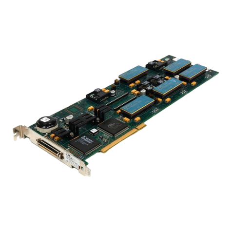
DDC SB-3642 User manual

DATA DEVICE CORPORATION
Data Device Corporation SB-3642 Manual
www.ddc-web.com Rev D – 4/19
i
SB-3642 SYNCHRO/RESOLVER-TO-DIGITAL
PMC INTERFACE CARD HARDWARE MANUAL
MN-3642XX-001
The information provided in this Manual is believed to be accurate; however, no
responsibility is assumed by Data Device Corporation for its use, and no license or rights
are granted by implication or otherwise connection therewith.
Specifications are subject to change without notice.
Please visit our Web site at http://www.ddc-web.com/ for the latest information.
All rights reserved. No part of this Manual may be reproduced or transmitted in any form
or by any mean, electronic, mechanical photocopying recording, or otherwise, without
the prior written permission of Data Device Corporation.
105 Wilbur Place
Bohemia, New York 11716-2426
Tel: (631) 567-5600, Fax: (631) 567-7358
World Wide Web -http://www.ddc-web.com
For Technical Support - 1-800-DDC-5757 ext. 7771
United Kingdom -Tel: +44-(0)1635-811140, Fax: +44-(0)1635-32264
France -Tel: +33-(0)1-41-16-3424, Fax: +33-(0)1-41-16-3425
Germany - Tel: +49-(0)89-15 00 12-11, Fax: +49-(0)89-15 00 12-22
Japan -Tel: +81-(0)3-3814-7688, Fax: +81-(0)3-3814-7689
Asia -Tel: +65 6489 4801
India - Tel: +91 080 301 10 200 © 2017 Data Device Corp.

RECORD OF CHANGE
Data Device Corporation SB-3642 Manual
www.ddc-web.com Rev D – 4/19
ii
Revision Date Pages Description
Pre A 12/2016 All Preliminary Release
Pre B 2/2017 All Updated Preliminary Release
Pre C 4/2017 All Updated Preliminary Release
Pre D 6/2017 All Updated Preliminary Release
Rev A 10/2017 All Initial Release
Rev B 2/2018 22 – 24 Updated software support information
Rev C 2/2019 All Added additional ordering options, aligned channel
enumeration to match software
Rev D 4/2019 9-12 Spec table description updated

TABLE OF CONTENTS
Data Device Corporation SB-3642 Manual
www.ddc-web.com Rev D – 4/19
iii
1PREFACE.............................................................................................................1
1.1 Text Usage..................................................................................................................1
1.2 Standard Definitions....................................................................................................1
1.3 Special Handling and Cautions ...................................................................................1
1.4 Trademarks.................................................................................................................1
1.5 What is included in this manual?.................................................................................1
1.6 Technical Support .......................................................................................................2
2OVERVIEW ..........................................................................................................3
2.1 Features......................................................................................................................3
2.2 System Requirements.................................................................................................4
2.3Configuration Options..................................................................................................4
2.4 Applications.................................................................................................................4
2.5 Mechanical Design......................................................................................................5
2.6 Specifications..............................................................................................................9
3HARDWARE INSTALLATION ...........................................................................13
3.1 Hardware Configuration and Operation.....................................................................13
4DETAILED ARCHITECTURE.............................................................................14
4.1 PCI Interface.............................................................................................................14
4.2 Synchro/Resolver to Digital Channels .......................................................................15
4.3 Additional Functionality .............................................................................................18
4.4 Card Pinouts .............................................................................................................21
5SOFTWARE .......................................................................................................24
5.1 Software Overview....................................................................................................24
6ORDERING INFORMATION ..............................................................................26

LIST OF FIGURES
Data Device Corporation SB-3642 Manual
www.ddc-web.com Rev D – 4/19
iv
Figure 1. SB-3642 Resolver-to-Digital PMC Card (4-channel card shown)...............................6
Figure 2. SB-3642 Architecture (8-channel card removes AqB, BIT, and Discrete IO from front
panel connector to accommodate additional 4 channels)....................................................7
Figure 3. SB-3642 Mechanical Outline......................................................................................8
Figure 4. Incremental Encoder Emulation Resolution Control.................................................20
Figure 5. Incremental Encoder Emulation Timing....................................................................20
Figure 6. 68-Pin I/O Connector Photograph............................................................................23
Figure 7. 68-Pin I/O Connector Pin Locations .........................................................................23

LIST OF TABLES
Data Device Corporation SB-3642 Manual
www.ddc-web.com Rev D – 4/19
v
Table 1. Input Signal Options ....................................................................................................4
Table 2. SB-3642 Specification Table (Note 1).........................................................................9
Table 3. Dynamic Characteristics............................................................................................16
Table 4. Tracking to Bandwidth Relationship...........................................................................16
Table 5. Velocity Characteristics .............................................................................................17
Table 6. BIT Fault Conditions..................................................................................................17
Table 7. Signal List..................................................................................................................21
Table 8. Front Panel Connector Pinout ...................................................................................22
Table 9. Supplied I/O Mating Connector Components ............................................................23
Table 10. Motion Feedback Library C SDK Part Number Descriptions ...................................24

Data Device Corporation SB-3642 Manual
www.ddc-web.com Rev D – 4/19
1
1 PREFACE
This manual uses typographical conventions to assist the reader in understanding the
content. This section will define the text formatting used in the rest of the manual.
1.1 Text Usage
•BOLD – indicates important information and table, figure, and chapter
references.
•Courier New – indicates code examples.
•<…> - indicates user - entered text or commands.
1.2 Standard Definitions
PCI Peripheral Component Interconnect
PMC PCI Mezzanine Card
1.3 Special Handling and Cautions
The SB-3642series uses state-of-the-art components, and proper care should be
used to ensure that the device will not be damaged by Electrical Static Discharge
(ESD), physical shock, or improper power surges and that precautions are taken to
avoid electrocution.
Warnings: Turn off power to the computer hardware and unplug from wall.
NEVER insert or remove card with power turned on.
Ensure that standard ESD precautions are followed. As a minimum, one
hand should be grounded to the power supply in order to equalize the static
potential.
Do not store disks in environments exposed to excessive heat, magnetic
fields or radiation.
1.4 Trademarks
All trademarks are the property of their respective owners.
1.5 What is included in this manual?
This manual contains a complete description of hardware installation and use.

PREFACE
Data Device Corporation SB-3642 Manual
www.ddc-web.com Rev D – 4/19
2
1.6 Technical Support
In the event that problems arise beyond the scope of this manual, you can contact
DDC by the following:
US Toll Free Technical Support:
1-800-DDC-5757, ext. 7771
Outside of the US Technical Support:
1-631-567-5600, ext. 7771
Fax:
1-631-567-5758 to the attention of Motion Feedback Technologies Applications
DDC Website:
www.ddc-web.com/ContactUs/TechSupport.aspx
Please note that the latest revisions of Software and Documentation are available for
download at DDC’s Web Site, www.ddc-web.com.

Data Device Corporation SB-3642 Manual
www.ddc-web.com Rev D – 4/19
3
2 OVERVIEW
The SB-3642 is a Front-I/O PCI Mezzanine Card (PMC) with up to eight channels of
Synchro or Resolver conversion. The SB-3642utilizes a PCI interface (Revision 3.0
Compliant 32-bit, 33/66 MHz). It is available in the industrial and commercial operating
temperature ranges.
The conversion in each channel utilizes DDC’s RD-19230 converter, which has a long
history of proven performance. For complete converter specifications, the RD-19230
Datasheet can be downloaded from the DDC website.
2.1 Features
Resolver Conversion
•Four or Eight Independent Resolver-to-Digital Channels
- 2V, 11.8Vrms, and 90Vrms Synchro and Resolver Ordering Options
•Utilizes High Accuracy RD-19230 Converters
•Software Programmable Resolution (10,12,14, or 16 bits)
•Software Programmable Bandwidth (Low or High Bandwidth)
•Self-Test, Built-in-Test, and Velocity Outputs
•Incremental Encoder Emulation (A quad B outputs) with Independent
Resolution Control (4-channel ordering option only)
•Configurable Two-Speed Conversion
•Synthesized Reference and Independent Reference Inputs for Each Channel
General
•VITA-47 Shock and Vibration Tested
•RoHS Compliant (Lead-free and hazardous substance-free)
•-40⁰ to +85⁰C Temperature Range
•32-bit/66 MHz PCI Rev. 3.0 Compliant Interface
•Operates in 3.3V or 5V PCI Signaling Environments
•Front Panel I/O (68-Pin) Air-Cooled Design
•Only 5V & 3.3V Supply Required (+/- 12V not needed)
•Four Opto-Isolated Discrete Input and Four Discrete Outputs for External
Control Functions (4-channel ordering option only)

OVERVIEW
Data Device Corporation SB-3642 Manual
www.ddc-web.com Rev D – 4/19
4
The card includes SB-36030Sx Motion Feedback Library along with code samples
and detailed documentation. To install the latest official software from DDC, download
via DDC’s website at www.ddc-web.com/.
2.2 System Requirements
•PCI-PMC connector supporting 3.3 or 5V PCI signaling
•PCI-PMC connector with +5V and +3.3V supply voltage available
•A supported operating system
2.3 Configuration Options
Table 1. Input Signal Options
Ordering Option (x) SB-3642x
Signal Input Bandwidth
0 2V Single-Ended 80 Hz / 300 Hz
1 11.8Vrms Synchro 80 Hz / 300 Hz
2 11.8 Vrms Resolver 80 Hz / 300 Hz
3 90Vrms Synchro 80 Hz / 300 Hz
4 90Vrms Synchro 15 Hz / 45 Hz
2.4 Applications
The SB-3642 PMC card’s rugged construction and ability to operate over the industrial
temperature range makes it ideal for use in mission computers and other embedded
systems. This device can be combined with carrier cards for use in VME or cPCI
control systems employing 33/66MHz bus. The card also provides an ideal solution for
encoder-based systems that will mate with Resolver inputs. The card is a valuable
addition to design and test teams involved with resolver simulation and positioning.
Resolvers are used in applications that include modern high performance industrial
and military position feedback and control systems. Typical motion feedback
applications include motor control, machine tool control, antenna control, robotics, and
process control systems.

OVERVIEW
Data Device Corporation SB-3642 Manual
www.ddc-web.com Rev D – 4/19
5
2.5 Mechanical Design
The SB-3642is a Front-I/O air-cooled PCI Mezzanine Card (PMC) designed to meet
or exceed vibration requirements specified in VITA-47 for a class V2 in air-cooled
applications. The SB-3642card also features CCPMC (Conduction Cooled PMC)
thermal rails and connector “anti-fretting” mounting holes per VITA-20-2005.
The front panel I/O connector layout uses a 68-pin front panel connection. The board
has conduction rails that do not interfere with the front panel connector. The front
panel connector includes a metal backshell with fastening thumbscrews.
The SB-3642is designed to meet or exceed the humidity requirements of ANSI/VITA
47, and has been tested to withstand 95% humidity.
To operate within the specified -40 to +85°C operating temperature, supplemental air
cooling of 300 LFM (Linear Feet per Minute) in the system is required. The SB-3642
utilizes a custom heat sink design using the conduction cooled rails to efficiently
operate within the temperature range.
MTBF (Mean Time Between Failure) report is available upon factory request.

OVERVIEW
Data Device Corporation SB-3642 Manual
www.ddc-web.com Rev D – 4/19
9
2.6 Specifications
Table 2. SB-3642 Specification Table (Note 1)
These specs apply over the rated power supply, temperature, and reference frequency ranges: 10% signal
amplitude variation, and 10% harmonic distortion (for values without a tolerance already specified).
PARAMETER MIN TYP MAX UNITS
ANGLE POSITION INDICATION CHANNELS
Channel Count:
• SB-3642xF4 4 Channels
• SB-3642xF8 8 Channels
Resolution (Programmable) 10, 12, 14, or 16 Bits
Accuracy + Repeatability (Note 2) @ 47 Hz to
1kHz @ 400 Hz to
4kHz @ 4001 Hz to
7kHz
• SB-36420 (2Vrms Single Ended) – 1 + 1 LSB 5 + 1 LSB Arc-Minutes
• SB-36421 (11.8Vrms Synchro) – 1 + 1 LSB 5 + 1 LSB Arc-Minutes
• SB-36422 (11.8Vrms Resolver) – 1 + 1 LSB 5 + 1 LSB Arc-Minutes
• SB-36423 (90Vrms Synchro) – 2 + 1 LSB 5 + 1 LSB Arc-Minutes
• SB-36424 (90Vrms Synchro) 2 + 1 LSB – – Arc-Minutes
Signal Input Voltage and Impedance Dependent on Card Ordering Option
SB-36420
(Note 3) SB-36421
SB-36422 SB-36423
SB-36424
• Synchro – 11.8 90 Vrms L-L
- Zin line-to-line – 52k 195k Ohms
- Zin each line-to-ground – 35k 130k Ohms
• Resolver 2 11.8 – Vrms L-L
- Zin single-ended (Note 4)10M min || 20F 70k – Ohms
- Zin Differential – 140k – Ohms
• Common-mode Range – 30 – V max
Reference Input Parameters Dependent on Card Ordering Option
SB-36420 SB-36421
SB-36422 SB-36423 SB-36424
• Carrier Frequency 360 to 7k 360 to 7k 360 to 1k 47 to 400 Hz
• Type Differential or Single-ended
• Voltage Range 2 to 130 Vrms
• Input Impedance (Note 5)
- Zin Single-Ended 400 kΩ
- Zin Differential 800 kΩ

OVERVIEW
Data Device Corporation SB-3642 Manual
www.ddc-web.com Rev D – 4/19
10
Table 2. SB-3642 Specification Table (Note 1)
These specs apply over the rated power supply, temperature, and reference frequency ranges: 10% signal
amplitude variation, and 10% harmonic distortion (for values without a tolerance already specified).
PARAMETER MIN TYP MAX UNITS
DYNAMIC CHARACTERISTICS AT 400 HZ NOMINAL CARRIER F.
At Resolution 10 12 14 16 Bits
At Bandwidth Low Note 6 Note 6 80 80 Hz
High 300 300 Note 7 Note 7 Hz
• Max. Tracking Rate 320 80 20 5 RPS
• Velocity Scale Factor 0.0125 0.05 0.2 0.8 Volts / RPS
DYNAMIC CHARACTERISTICS AT 60 HZ NOMINAL CARRIER F.
At Resolution 10 12 14 16 Bits
At Bandwidth Low Note 6 Note 6 15 15 Hz
High 45 45 Note 7Note 7 Hz
• Max. Tracking Rate 32 8 2 0.5 RPS
• Velocity Scale Factor 0.125 0.5 2 8 Volts / RPS
VELOCITY OUTPUT CHARACTERISTICS
Voltage Range -4.0 4.0 V
Scale Factor Error 10 20 %
Scale Factor TC 100 200 PPM / ºC
Reversal Error 1 2 %
Linearity 0.5 1 % output
Zero Offset 5 15 mV
Zero Offset TC 15 30 µV / ºC
Load 10 kΩ
BIT FAULT CONDITIONS (Note 8) Dependent on Card Ordering Option
(hardware pin available on 4-channel board only) SB-36420 SB-36421
SB-36422 SB-36423
SB-36424
Loss of Signal (LOS) when SIN & COS is below… 0.5 Vrms 3 VLL 22.5 VLL
Loss of Reference (LOR) when reference is below… 1.0 Vrms
Loss of Tracking (LOT) when difference between digital
output and analog input exceeds… 100 LSBs in the positive direction, or 250 LSBs in
the negative direction LSBs
180º Phase Error when input signal to reference input
gives false null 180º Out of Phase Degrees
DIGITAL OUTPUTS DRIVE CAPABILITY (A, B, ZIP,
BIT signals)
Logic 0, 1 TTL load at 0.4V max. 1.6 mA
Logic 1, 10 TTL loads at 2.8V min. 0.4 mA

OVERVIEW
Data Device Corporation SB-3642 Manual
www.ddc-web.com Rev D – 4/19
11
Table 2. SB-3642 Specification Table (Note 1)
These specs apply over the rated power supply, temperature, and reference frequency ranges: 10% signal
amplitude variation, and 10% harmonic distortion (for values without a tolerance already specified).
PARAMETER MIN TYP MAX UNITS
DISCRETE DIGITAL I/O (4-channel board only), see
Para. 4.3.3
VIL 3 V
VIH 30 V
VOL 1.5 V
VOH 30 V
POWER SUPPLY REQUIREMENTS (Note 9)
Voltages/Tolerances
+5 V 4.75 5 5.25 V
+3.3 V 3.0 3.3 3.6 V
Current Drain (+5V) 0.20 A
Current Drain (+3.3V) 0.60 A
PCI INTERFACE
Bit Size 32 bits
Clock Speed 66 MHz
Bus Signaling (Universal Bus Voltage) 3.3 / 5 V
COOLING METHOD
Air-cooled (Required for industrial temp. range) 300 LFM
THERMAL
Card Operating Temperature Range (2A0)
with 300 LFM air-flow -40 +85 °C
Storage Temperature -65 +150 °C
MECHANICAL DESIGN
Shock Vita-47 / MIL-STD-810, TM516, Class S1 for CC (50 g, 11ms, half-
sine, 18 shocks total)
Vibration Vita-47 / MIL-STD-810, TM514, “V2” (AC)
Humidity Vita-47 / MIL-STD-810, TM507, Procedure II
PHYSICAL CHARACTERISTICS
Size 2.91 x 5.87 x 0.39 (74.0 x 149.0 x 10.0) in. (mm.)
Weight 4.16 (118)oz. (g)

OVERVIEW
Data Device Corporation SB-3642 Manual
www.ddc-web.com Rev D – 4/19
12
Table 2. SB-3642 Specification Table (Note 1)
These specs apply over the rated power supply, temperature, and reference frequency ranges: 10% signal
amplitude variation, and 10% harmonic distortion (for values without a tolerance already specified).
PARAMETER MIN TYP MAX UNITS
Notes:
1. The specifications apply over the rated power supply, temperature, and reference frequency ranges.
2. Accuracy is tested in 16 bit resolution. Expect ± 1 LSB of jitter for frequencies less than or equal to 1 kHz.
3. Direct input requires SIN input, COS input, and a common ground.
4. || = “in parallel with”
5. Minimum impedance is guaranteed over the operating range, but is not tested.
6. Exceeds Tracking Rate / Bandwidth Ratio, See Table 4. An instantaneous large step angle increment can cause spin-
around condition. To avoid spin-around at power up, the default condition is 16 Bit resolution and Low Bandwidth.
7. Carrier Frequency / Bandwidth Ratio of 5X is recommended to maintain jitter < 1 LSB
8. For more information, see section on Built-In-Test (BIT) Output
9. All power measurements were taken with a 66-MHz PCI bus.

Data Device Corporation SB-3642 Manual
www.ddc-web.com Rev D – 4/19
13
3 HARDWARE INSTALLATION
The SB-3642 card is a 32-bit, 33/66 MHz PCI Local Bus Rev. 3.0 compliant interface
target device that may be inserted into any compatible slot. Note that this card is
capable of universal PCI signal and automatically defaults to 3.3V or 5V depending on
the host bus.
When installing the card, the following should be observed:
•NEVER insert or remove the card with the power turned on.
•ALWAYS take proper precautions to guard against static damage.
•Use a wrist strap if available, or ensure proper static grounding by touching the
power supply cover WITH POWER OFF.
•Insert the card at a slight angle so that the connectors first protrude from the
rear opening and then gently press the card into the motherboard connector.
Secure with proper hardware.
•Make sure that adjacent cabling and wiring do not hinder the airflow around the
card.
This card is designed as a Plug-and-Play device and as such, there are no jumpers or
switches to be set for address and interrupt selection.
3.1 Hardware Configuration and Operation
The SB-3642card utilizes the PCI interface, and the configuration for Plug-and-Play
PCI is performed by the operating system. During the initial power on boot process,
the system performs an enumeration of the PCI bus and allocates a resource
configuration that satisfies the card requirements. The system will save the
configuration information in the SB-3642’s PCI configuration space registers. These
registers are configured at the factory to contain information that identifies the card
type, vendor, required memory sizes, and interrupt resources. When the driver loads,
it will access the configuration registers and identify how the system has configured
the card. After identifying each of the installed cards, the device driver will enumerate
each of the channels on the card and create a configuration structure that defines the
allocated address and interrupt. The end user does not need to know this information
if using one of the supplied C API libraries to operate the card.

Data Device Corporation SB-3642 Manual
www.ddc-web.com Rev D – 4/19
14
4 DETAILED ARCHITECTURE
4.1 PCI Interface
The card provides a target 32-bit PCI interface, as defined in the PCI Local Bus
Specification, Rev 3.0, which operates at clock speeds of up to 66 MHz for
applications where a higher bus speed is desired. If a 33 MHz device was placed on a
66 MHz bus, the bus speed would be forced to slow down to 33 MHz. Although
resolver simulation may not require the additional bandwidth of a 66 MHz bus, the SB-
364266 MHz device allows the base CPU PCI bus to run at 66 MHz, enabling other
high-speed devices on the bus to take advantage of the higher bandwidth.
When using the card with the supplied Motion Feedback C SDK (SB-36030Sx) and
drivers there is no need to reference the PCI configuration registers.
Connection to the host is established through the card’s Pn1 and Pn2 connectors. PCI
64 bit extension is not supported, the PMC Pn3 for PCI 64 bit extension and Pn4 for
user I/O connectors are not populated on the card.
4.1.1 Use with 5V PCI Signaling
The PCI interface signals on the SB-3642support +3.3V or +5V signaling. The device
incorporates both 3.3V and 5V signal keying holes.
4.1.2 Register & Memory Addressing
The SB-3642PCI interface contains a set of "Type 00h" PCI configuration registers
that are used to map the device into the host system. The configuration register space
is mapped in accordance with PCI Revision 3.0 specifications. These registers are
arranged such that all memory and register space may be addressed through a single
PCI function.
Configuration registers implement the Subsystem Vendor and Device ID, and control
the Fail-Safe operation of the device. There is one Base Address Registers (BAR)
used on the design of this card. All BAR mapping is located in PCI configuration
register space.
When using this card with DDC's driver and the API library software, the details of
these registers and memory addresses are abstracted from the user to provide an
easy-to-use High Level “C” programming environment.

DETAILED ARCHITECTURE
Data Device Corporation SB-3642 Manual
www.ddc-web.com Rev D – 4/19
15
4.2 Synchro/Resolver to Digital Channels
4.2.1 Signal Interface
The front panel connector provides signal connections for all channels. These signals
include S1, S2, S3, S4 inputs and differential reference inputs RH and RL. See below
to identify which inputs are applicable to the selected model number.
Configuration for the resolver inputs is accomplished by the use of specific thin film
resistor networks installed on the card. These networks scale the input voltage to the
converter for a 2V, 11.8V, or 90V resolver or synchro full scale input signal.
Below are the input signal designations for synchro, resolver, and single-ended mode:
•Synchro Mode Connect (SB-36421, SB-36423, SB-36424)
- S1
- S2
- S3
- S4 is not used
•Resolver Mode Connect (SB-36422)
- S3 = +SIN
- S1 = -SIN
- S2 = +COS
- S4 = -COS
•Single-ended Mode Connect (SB-36420)
- S2 = +COS
- S3 = +SIN
When using single ended configuration, S1 and S4 need to be returned to the analog
ground using the associated analog ground pin, see pinout in Error! Reference
source not found..
4.2.1 Bandwidth
The user can program each channel independently for one of two bandwidth settings
through software. The bandwidth selection is programmable for either 80 or 300 Hz.
The bandwidth selection configures the converters’ bandwidth setting in order to
optimize signal noise rejection and dynamic response. For best dynamics, the rule of
thumb is bandwidth should be less than or equal to ¼ of the Resolver carrier
frequency, Fc.
For instance, a 400 Hz Resolver (Fc= 400Hz) should nominally have a converter
bandwidth set at 400 Hz / 4 = 100 Hz or less. In the case of SB-3642, the low
bandwidth is set to 80 Hz. This bandwidth setting would be an appropriate selection
for 400Hz carrier frequency.
Table of contents
Other DDC Computer Hardware manuals
Popular Computer Hardware manuals by other brands

Panasonic
Panasonic 2SA2079 Specification sheet

SMC Networks
SMC Networks EliteConnect SMC2531W-B EU Specifications

MiTAC
MiTAC TYAN GN70-B7086 Service engineer's manual

Jabra
Jabra A330 Multiuse Technical specifications

NEC
NEC SX-Aurora TSUBA300-8ASA user guide

Computer Automation Technology
Computer Automation Technology AP-100 instruction manual