DDC SB-3625XKX User manual

DATA DEVICE CORPORATION
Data Device
Corporation SB-3625XKX Manual
www.ddc-web.com Rev D - 2/19
i
SB-3625XKX SYNCHRO/RESOLVER-TO-DIGITAL
PCIE INTERFACE BOARD HARDWARE MANUAL
MN-3625XKX-001
The information provided in this Manual is believed to be accurate; however, no
responsibility is assumed by Data Device Corporation for its use, and no license or rights
are granted by implication or otherwise connection therewith.
Specifications are subject to change without notice.
Please visit our Web site at http://www.ddc-web.com/ for the latest information.
All rights reserved. No part of this Manual may be reproduced or transmitted in any form
or by any mean, electronic, mechanical photocopying recording, or otherwise, without
the prior written permission of Data Device Corporation.
105 Wilbur Place
Bohemia, New York 11716-2426
Tel: (631) 567-5600, Fax: (631) 567-7358
World Wide Web -http://www.ddc-web.com
For Technical Support - 1-800-DDC-5757 ext. 7771
United Kingdom -Tel: +44-(0)1635-811140, Fax: +44-(0)1635-32264
France -Tel: +33-(0)1-41-16-3424, Fax: +33-(0)1-41-16-3425
Germany Tel: +49-(0)89-15 00 12-11, Fax: +49-(0)89-15 00 12-22
Japan -Tel: +81-(0)3-3814-7688, Fax: +81-(0)3-3814-7689
Asia -Tel: +65 6489 4801
India -Tel: +09-080-301-200 © 2016 Data Device Corp.

RECORD OF CHANGE
Data Device
Corporation SB-3625XKX Manual
www.ddc-web.com Rev D - 2/19
ii
Revision Date Pages Description
A 5/2016 All Initial Release
B 12/2017 14, 15 Added section 6.2.4, and figures 6 and 7.
C 2/2018 5 Accuracy section of Spec table updated.
D 2/2019 8, 9, 11
Updated connector pinout table to match mating
connector figure.
Aligned channel enumeration pinout to match software.

TABLE OF CONTENTS
Data Device
Corporation SB-3625XKX Manual
www.ddc-web.com Rev D - 2/19
iii
1SOFTWARE LICENSE AND POLICIES ..............................................................1
2PREFACE.............................................................................................................1
2.1 Text Usage..................................................................................................................1
2.2Special Handling and Cautions ...................................................................................1
2.3 Trademarks.................................................................................................................1
2.4 What is included in this manual? .................................................................................2
2.5 Technical Support .......................................................................................................2
3OVERVIEW ..........................................................................................................3
3.1 Features......................................................................................................................3
3.2 System Requirements .................................................................................................3
3.3 Applications.................................................................................................................4
4SPECIFICATIONS................................................................................................5
5HARDWARE ........................................................................................................7
5.1 Installation...................................................................................................................7
5.2 Configuration...............................................................................................................8
5.2.1 JN4 96-pin Mating Connector............................................................................8
5.2.2 P5 68-Pin Connector .......................................................................................10
6DETAILED ARCHITECTURE.............................................................................12
6.1 Mechanical Outline....................................................................................................12
6.2 Synchro / Resolver to Digital Channels .....................................................................13
6.2.1 Signal Connections .........................................................................................13
6.2.2 Bandwidth .......................................................................................................13
6.2.3 Synthesized Reference ...................................................................................14
6.2.4 Transient Protection ........................................................................................14
6.2.5 Incremental Encoder Emulation (A Quad B)....................................................16
6.2.6 Velocity Output................................................................................................17
6.2.7 Built-in-Test (BIT) Output ................................................................................17
6.2.8 Two Speed......................................................................................................18
6.2.9 Self-Test..........................................................................................................18
7SOFTWARE .......................................................................................................19
8ORDERING INFORMATION ..............................................................................21

LIST OF FIGURES
Data Device
Corporation SB-3625XKX Manual
www.ddc-web.com Rev D - 2/19
iv
Figure 1. SB-3625XKX Synchro/Resolver-to-Digital PCIe Board .............................................. 4
Figure 2. SB-3625XKX PCIe Board Block Diagram................................................................... 8
Figure 3. JN4 96-Pin Mating Connector .................................................................................... 8
Figure 4. P5 68-Pin D-Type Mating Connector........................................................................ 10
Figure 5. SB3625XKX Mechanical Outline ............................................................................. 12
Figure 6. Voltage Transient Suppressor, 90V Synchro Input................................................... 14
Figure 7. Voltage Transient Suppressor, 90V Resolver Input.................................................. 15
Figure 8. Incremental Encoder Emulation Timing.................................................................... 16

LIST OF TABLES
Data Device
Corporation SB-3625XKX Manual
www.ddc-web.com Rev D - 2/19
v
Table 1. SB-3625XKX Specifications ........................................................................................ 5
Table 2. JN4 96-Pin Connector Pinout ...................................................................................... 9
Table 3. P5 68-Pin Connector Pin Out .................................................................................... 11
Table 4. Dynamic Characteristics ............................................................................................ 13
Table 5. Velocity Characteristics ............................................................................................. 17
Table 6. BIT Fault Conditions .................................................................................................. 17

Data Device
Corporation SB-3625XKX Manual
www.ddc-web.com Rev D - 2/19
1
1 SOFTWARE LICENSE AND POLICIES
IMPORTANT—READ CAREFULLY: This Software License Agreement (“SLA”) is a
legal agreement between you (either an individual or a single entity) and Data Device
Corporation (DDC) for this DDC software product, which includes computer software
and may include associated media, printed materials, and “online” or electronic
documentation (“Product”). YOU AGREE TO BE BOUND BY THE TERMS OF THIS
SLA BY INSTALLING, COPYING, OR OTHERWISE USING THE PRODUCT. IF YOU
DO NOT AGREE, DO NOT INSTALL OR USE THE PRODUCT; YOU MAY RETURN
IT TO YOUR PLACE OF PURCHASE FOR A FULL REFUND.
GRANT OF LICENSE
DDC grants you the following rights provided that you comply with all terms and
conditions of this SLA:
•Installation and use. You may install, use, access, display and run one copy of
the Product on a single computer, such as a workstation, terminal or other
device (“Workstation Computer”). The Product may not be used in conjunction
with non-DDC devices. You may not use the Product to permit any Device to
use, access, display or run other executable software residing on the
Workstation Computer, nor may you permit any Device to use, access, display,
or run the Product or Product’s user interface, unless the Device has a
separate license for the Product.
•Storage/Network Use. You may also store or install a copy of the Product on a
storage device, such as a network server, used only to install or run the
Product on your other Workstation Computers over an internal network;
however, you must acquire and dedicate an additional license for each
separate Workstation Computer on or from which the Product is installed, used,
accessed, displayed or run. A license for the Product may not be shared or
used concurrently on different Workstation Computers.
•Reservation of Rights. DDC reserves all rights not expressly granted to you in
this SLA.
UPGRADES
To use a Product identified as an upgrade, you must first be licensed for the product
identified by DDC as eligible for the upgrade. After upgrading, you may no longer use
the product that formed the basis for your upgrade eligibility.

SOFTWARE LICENSE AND POLICIES
Data Device
Corporation SB-3625XKX Manual
www.ddc-web.com Rev D - 2/19
2
ADDITIONAL SOFTWARE/SERVICES
This SLA applies to updates of the Product that DDC may provide to you or make
available to you after the date you obtain your initial copy of the Product, unless we
provide other terms along with the update.
TRANSFER
You may move the Product to a different Workstation Computer. After the transfer,
you must completely remove the Product from the former Workstation Computer. You
may not rent, lease, lend or provide commercial services to third parties with the
Product.
LIMITATION ON REVERSE ENGINEERING, DECOMPILATION, AND
DISASSEMBLY
You may not reverse engineer, decompile, or disassemble the Product.
TERMINATION
Without prejudice to any other rights, DDC may cancel this SLA if you do not abide by
the terms and conditions of this SLA, in which case you must return all copies of the
Product and all of its component parts.
EXPORT RESTRICTIONS
You acknowledge that the Product is of U.S. origin and subject to U.S. export
jurisdiction. You agree to comply with all applicable international and national laws
that apply to the Product, including the U.S. Export Administration Regulations, as well
as end-user, end-use, and destination restrictions issued by U.S. and other
governments.
LIMITED WARRANTY FOR PRODUCT
DDC warrants that the Product will perform substantially in accordance with the
accompanying materials for a period of one (1) year from the date of receipt. Except
for the warranty made above, DDC makes no warranty or representation of any kind,
express or implied, with respect to the Products, including warranty as to their
merchantability or fitness for a particular purpose or as to any other matter. All claims
based upon defects shall be deemed waived unless made in writing and received by
DDC within one (1) year after your receipt of the Product. New Product updates are
available without charge during this one (1) year term of this warranty.

SOFTWARE LICENSE AND POLICIES
Data Device
Corporation SB-3625XKX Manual
www.ddc-web.com Rev D - 2/19
3
ANNUAL MAINTENANCE CONTRACT
After the expiration of the one (1) year limited warranty period, a Maintenance
Contract may be purchased from DDC to extend the Product warranty period for an
additional one (1) year from date of expiration. With the purchase of a valid Annual
Maintenance Contract, the clauses defined in Section 8 shall remain intact.
Maintenance Contracts can be renewed annually and must remain valid, without any
lapses, to extend the Product warranty period.
LIMITATION ON REMEDIES; NO CONSEQUENTIAL OR OTHER
DAMAGES
Your exclusive remedy for any breach of this Limited Warranty is as set forth below.
Except for any refund elected by DDC, YOU ARE NOT ENTITLED TO ANY
DAMAGES, INCLUDING BUT NOT LIMITED TO CONSEQUENTIAL DAMAGES, if
the Product does not meet DDC’s Limited Warranty, and, to the maximum extent
allowed by applicable law, even if any remedy fails of its essential purpose. The terms
of Section 0 below (“Exclusion of Incidental, Consequential and Certain Other
Damages”) are also incorporated into this Limited Warranty. You may have others,
which vary from state/jurisdiction to state/jurisdiction.
YOUR EXCLUSIVE REMEDY
DDC’s and its suppliers’ entire liability and your exclusive remedy shall be, at DDC’s
option from time to time exercised subject to applicable law, (a) return of the price paid
(if any) for the Product, or (b) repair or replacement of the Product, that does not meet
this Limited Warranty and that is returned to DDC. You will receive the remedy elected
by DDC without charge, except that you are responsible for any expenses you may
incur (e.g. cost of shipping the Product to DDC). This Limited Warranty is void if failure
of the Product has resulted from accident, abuse, misapplication, abnormal use or a
virus. Any replacement Product will be warranted for the remainder of the original
warranty period or thirty (30) days, whichever is longer.
DISCLAIMER OF WARRANTIES
The Limited Warranty that appears above is the only express warranty made to you
and is provided in lieu of any other express warranties (if any) created by any
documentation, packaging, or other communications. Except for the Limited Warranty
and to the maximum extent permitted by applicable law, DDC and its suppliers provide
the Product and support services (if any) AS IS AND WITH ALL FAULTS, and hereby
disclaim all other warranties and conditions, either express, implied or statutory,
including, but not limited to, any (if any) implied warranties, duties or conditions of
merchantability, of fitness for a particular purpose, of reliability or availability, of
accuracy or completeness of responses, of results, of workmanlike effort, of lack of
viruses, and of lack of negligence, all with regard to the Product, and the provision of

SOFTWARE LICENSE AND POLICIES
Data Device
Corporation SB-3625XKX Manual
www.ddc-web.com Rev D - 2/19
4
or failure to provide support or other services, information, software, and related
content through the Product or otherwise arising out of the use of the Product.
EXCLUSION OF INCIDENTAL, CONSEQUENTIAL AND CERTAIN
OTHER DAMAGES
TO THE MAXIMUM EXTENT PERMITTED BY APPLICABLE LAW, IN NO EVENT
SHALL DDC OR ITS SUPPLIERS BE LIABLE FOR ANY SPECIAL, INCIDENTAL,
PUNITIVE, INDIRECT, OR CONSEQUENTIAL DAMAGES WHATSOEVER
(INCLUDING, BUT NOT LIMITED TO, DAMAGES FOR LOSS OF PROFITS OR
CONFIDENTIAL OR OTHER INFORMATION, FOR BUSINESS INTERRUPTION,
FOR PERSONAL INJURY, FOR LOSS OF PRIVACY, FOR FAILURE TO MEET ANY
DUTY INCLUDING OF GOOD FAITH OR OF REASONABLE CARE, FOR
NEGLIGENCE, AND FOR ANY OTHER LOSS WHATSOEVER) ARISING OUT OF
OR IN ANY WAY RELATED TO THE USE OF OR INABILITY TO USE THE
PRODUCT, THE PROVISION OF OR FAILURE TO PROVIDE SUPPORT OR
OTHER SERVICES, INFORMATON, SOFTWARE, AND RELATED CONTENT
THROUGH THE PRODUCT OR OTHERWISE ARISING OUT OF THE USE OF THE
PRODUCT, OR OTHERWISE UNDER OR IN CONNECTION WITH ANY
PROVISION OF THIS SLA, EVEN IN THE EVENT OF THE FAULT, TORT
(INCLUDING NEGLIGENCE), STRICT LIABILITY, BREACH OF CONTRACT OR
BREACH OF WARRANTY OF DDC OR ANY SUPPLIER, AND EVEN IF DDC OR
ANY SUPPLIER HAS BEEN ADVISED OF THE POSSIBILITY OF SUCH DAMAGES.
LIMITATION OF LIABILITY AND REMEDIES
Notwithstanding any damages that you might incur for any reason whatsoever
(including, without limitation, all damages referenced above and all direct or general
damages), the entire liability of DDC and any of its suppliers under any provision of
this SLA and your exclusive remedy for all of the foregoing (except for any remedy of
repair or replacement elected by DDC with respect to any breach of the Limited
Warranty) shall be limited to the amount actually paid by you for the Product. The
foregoing limitations, exclusions and disclaimers (including Sections 0, 0, 0, and
0above) shall apply to the maximum extent permitted by applicable law.
U.S. GOVERNMENT LICENSE RIGHTS
All Product provided to the U.S. Government is provided with the commercial license
rights and restrictions described elsewhere herein.
APPLICABLE LAW
This SLA is governed by the laws of the State of New York.

SOFTWARE LICENSE AND POLICIES
Data Device
Corporation SB-3625XKX Manual
www.ddc-web.com Rev D - 2/19
5
ENTIRE AGREEMENT
This SLA (including any addendum or amendment to this SLA which is included with
the Product) are the entire agreement between you and DDC relating to the Product
and the support services (if any) and they supersede all prior or contemporaneous
oral or written communications, proposals and representations with respect to the
Product or any other subject matter covered by this SLA. To the extent the terms of
any DDC policies or programs for support services conflict with the terms of this SLA,
the terms of this SLA shall control.
The Product is protected by copyright and other intellectual property laws and treaties.
DDC or its suppliers own the title, copyright, and other intellectual property rights in
the Product. The Product is licensed, not sold.

Data Device
Corporation SB-3625XKX Manual
www.ddc-web.com Rev D - 2/19
1
2 PREFACE
This manual uses typographical conventions to assist the reader in understanding the
content. This section will define the text formatting used in the rest of the manual
2.1 Text Usage
•BOLD–indicates important information and table, figure, and chapter
references.
•Courier New–indicates code examples.
•<…> - indicates user-entered text or commands.
2.2 Special Handling and Cautions
The SB-3625XKX series uses state-of-the-art components, and proper care should be
used to ensure that the device will not be damaged by Electrical Static Discharge
(ESD), physical shock, or improper power surges and that precautions are taken to
avoid electrocution.
Warnings: Turn off power to the computer hardware and unplug from wall.
NEVER insert or remove board with power turned on.
Ensure that standard ESD precautions are followed. As a minimum, one
hand should be grounded to the power supply in order to equalize the static
potential.
Do not store disks in environments exposed to excessive heat, magnetic
fields or radiation.
2.3 Trademarks
All trademarks are the property of their respective owners.

PREFACE
Data Device
Corporation SB-3625XKX Manual
www.ddc-web.com Rev D - 2/19
2
2.4 What is included in this manual?
This manual contains a hardware guide for the SB-3625XKX PCIe Board and a basic
overview of the software supplied with the board. The Synchro API Library and Driver
installations for Windows will be covered in the separate SB-36040S0 manual, as well
as LabVIEW™ Support Software for Windows.
2.5 Technical Support
In the event that problems arise beyond the scope of this manual, you can contact
DDC by the following:
US Toll Free Technical Support:
1-800-DDC-5757, ext. 7771
Outside of the US Technical Support:
1-631-567-5600, ext. 7771
Fax:
1-631-567-5758 to the attention of Motion Feedback Technologies Applications
DDC Website:
www.ddc-web.com/ContactUs/TechSupport.aspx
Please note that the latest revisions of Software and Documentation are available for
download at DDC’s Web Site, www.ddc-web.com.

Data Device
Corporation SB-3625XKX Manual
www.ddc-web.com Rev D - 2/19
3
3 OVERVIEW
The SB-3625XKX PCIe board provides intelligent interfacing between a Synchro or
Resolver's output and a PCIe Bus.
3.1 Features
•Plug-and-Play (PnP) compatible for easy installation
•Utilizes RD-19230 converters
•Software-Programmable Resolution (10,12,14 or 16 bits)
•Software-Programmable Bandwidth
•Self-Test
MFBA GUI software has the capability to display position for either eight channels of
single speed or four channels of two-speed. Also included with each board is the
Synchrolib.dll Runtime Library with sample code that allows users to easily write their
own software for the board. Please refer to the SB-36030S0 Software Manual
available on our website www.ddc-web.com for installation and function call
information.
To install the latest official software from DDC, download via DDC’s website at
www.ddc-web.com/Products/CardsMatrixSynchroResolver.aspx. Navigate to the
applicable product page and click on the software tab. A download link will be given
for the latest package(s) at no cost. System Requirements
3.2 System Requirements
The PC must be configured with a Windows or Linux operating system.

OVERVIEW
Data Device
Corporation SB-3625XKX Manual
www.ddc-web.com Rev D - 2/19
4
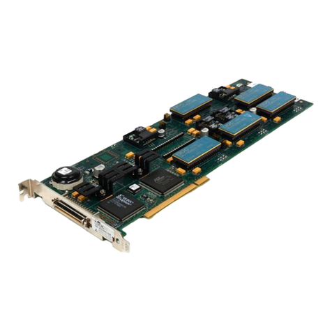
Figure 1. SB-3625XKX Synchro/Resolver-to-Digital PCIe Board
3.3 Applications
The SB-3625XKX is designed for test applications involving angle position
measurements from synchro and resolver sensors. Synchros and resolvers are used
in applications such as motor control, industrial automation, robotics, antenna
positioning, and valve control. This device is ideal for test engineers and developers to
perform lab testing on these types of applications. Applications include modern, high
performance industrial and military position feedback and control systems. Typical
motion feedback applications include motor control, machine tool control, antenna
control, robotics and process control systems. The SB-3625XKX is supplied with a
Graphical User Interface (GUI) to analyze position information, direction and BIT.

Data Device
Corporation SB-3625XKX Manual
www.ddc-web.com Rev D - 2/19
5
4 SPECIFICATIONS
Table 1. SB-3625XKX Specifications
These specifications apply over the rated power supply, temperature, and reference frequency ranges;
10% signal amplitude variation and 10% harmonic distortion
PARAMETER UNIT VALUE
RESOLUTION Bits 10, 12, 14, or 16 programmable (note 4)
ACCURACY
47 – 1k (note 2)
1k – 4k
4k – 7k
Option 0 (2V Single-ended) Minutes — 1 + 1 LSB 5 + 1 LSB
Option 1 (11.8V Synchro) Minutes — 1 + 1 LSB 5 + 1 LSB
Option 2(11.8V Resolver) Minutes — 1 + 1 LSB 5 + 1 LSB
Option 3 (90V Synchro 400Hz) Minutes — 2 + 1 LSB 5 + 1 LSB
Option 4 (90V Synchro 60Hz) Minutes 2 + 1 LSB — —
SIGNAL INPUT Solid State
Option Number
Option 0 Option 1, 2 Option 3, 4
Synchro
Vrms L-L
— 11.8 90
• Zin line-to-line
Ohms
— 52k 195k
• Zin each line-to-ground
Ohms
— 35k 130k
Resolver
Vrms L-L
2 Vrms direct (note 3) 11.8 —
• Zin single ended
Ohms
10M min || 20pf (note 1) 70k —
• Zin differential
Ohms
N/A 140k —
Common-mode Range
V max
N/A 30 max —
REFERENCE INPUT
Solid State
Signal Input Option Number
Option 0 Option 1, 2 Option 3 Option 4
Carrier Frequency
Hz
360 – 7k 360 – 7k 360 – 1k 47 – 400
Type
Differential Differential Differential Differential
Voltage Range
Vrms
2 – 40 2 – 40 50 – 130 50 – 130
Input Impedance
• single ended
Ohms
100k 100k 300k 300k
• differential
Ohms
50k 50k 200k 200k
Common-mode Range
Vpeak
50 50 200 200
DIGITAL OUTPUTS
A, B, Zero Index (ZI) 50pf+
Drive Capability Logic 0: 1 TTL load, 1.6mA at 0.4V max
Logic 1: 10 TTL Loads, = 0.4mA at 2.8V min
After set into A quad B mode Logic 0: 100mV max driving CMOS
Logic 1: +5V supply minus 100mV min driving CMOS

SPECIFICATIONS
Data Device
Corporation SB-3625XKX Manual
www.ddc-web.com Rev D - 2/19
6
Table 1. SB-3625XKX Specifications
These specifications apply over the rated power supply, temperature, and reference frequency ranges;
10% signal amplitude variation and 10% harmonic distortion
PARAMETER UNIT VALUE
POWER SUPPLY MIN TYP MAX
Voltage/Tolerances (per PCIe CEM)
+3.3V
+12V
V
V
3.003
11.04
3.3
12
3.597
12.96
Current
+3.3V
+12V
A
A
0.25
0.25
COOLING METHOD Air Cooled
TEMPERATURE RANGE
Operating °C 0 to +55
Storage °C -20 to +75
PHYSICAL CHARACTERISTICS
Size in 7.24 x 4.20 x 0.60
(mm) (183.85 x 106.62 x 15.24)
Weight oz 7.41 (max)
(g) (210 (max))
Table 1 notes:
1. || = “in parallel with”
2. If the frequency in between 47 and 1kHz, then there will be 1 LSB of jitter.
3. Direct input requires SIN input, COS input, and a common ground.
4. Signal input option #4 (90V Synchro 60Hz) not recommended for use in 16 bit resolution mode due to excessive jitter.

Data Device
Corporation SB-3625XKX Manual
www.ddc-web.com Rev D - 2/19
7
5 HARDWARE
5.1 Installation
The SB-3625XKX board is a PCI Express x1 1.0a compliant board that can be
inserted in any standard height PCI Express 1.0a/1.1/2.0 compliant slot. When
installing the board, the following should be observed:
•NEVER insert or remove the board with the power turned on.
•ALWAYS take proper precautions to guard against static damage.
•Use a wrist strap if available, or ensure proper static grounding by touching
the power supply cover WITH POWER OFF.
•Insert the board and gently press into the PCI Express mating connector.
Secure the rear I/O panel bracket with the proper hardware.
•ALWAYS secure both rear I/O panel brackets for the SB-3625XKX option.
•Make sure that adjacent cabling and wiring do not hinder the airflow around
the board.
The board is a true Plug and Play device and as such, there are no jumpers or
switches to be set for address or interrupt selection. Interrupts and memory selections
will be performed by the operating system as the boot system progresses.

HARDWARE
Data Device
Corporation SB-3625XKX Manual
www.ddc-web.com Rev D - 2/19
8
Figure 2. SB-3625XKX PCIe Board Block Diagram
5.2 Configuration
5.2.1 JN4 96-pin Mating Connector
Table 2 lists the pinouts and Figure 3 shows the mechanical assembly for the JN4
mating connector. Row B is No Connect.
Figure 3. JN4 96-Pin Mating Connector

HARDWARE
Data Device
Corporation SB-3625XKX Manual
www.ddc-web.com Rev D - 2/19
9
Table 2. JN4 96-Pin Connector Pinout
Pin Number JN4 Row A JN4 Row C
1 BIT – Channel 1 BIT – Channel 0
2 BIT – Channel 3 BIT – Channel 2
3 BIT – Channel 5 BIT – Channel 4
4 BIT – Channel 7 BIT – Channel 6
5 GND GND
6 RH – Channel 7 RH – Channel 1
7 RH – Channel 5 RH – Channel 2
8 RH – Channel 6 RH – Channel 3
9 RH – Channel 0 RH – Channel 4
10 GND GND
11 RL – Channel 1 RL – Channel 5
12 RL – Channel 6 RL – Channel 4
13 RL – Channel 7 RL – Channel 3
14 RL – Channel 0 RL – Channel 2
15 GND GND
16 S3 (+SIN) – Channel 4 S2 (+COS) – Channel 4
17 S1 (-SIN) – Channel 4 S4 (-COS) – Channel 4
18 S1 (-SIN) – Channel 3 S4 (-COS) – Channel 3
19 S3 (+SIN) – Channel 3 S2 (+COS) – Channel 3
20 GND GND
21 S3 (+SIN) – Channel 6 S2 (+COS) – Channel 6
22 S1 (-SIN) – Channel 6 S4 (-COS) – Channel 6
23 S3 (+SIN) – Channel 7 S2 (+COS) – Channel 7
24 S1 (-SIN) – Channel 7 S4 (-COS) – Channel 7
25 S3 (+SIN) – Channel 2 S2 (+COS) – Channel 2
26 S1 (-SIN) – Channel 2 S4 (-COS) – Channel 2
27 S3 (+SIN) – Channel 0 S2 (+COS) – Channel 0
28 S1 (-SIN) – Channel 0 S4 (-COS) – Channel 0
29 S1 (-SIN) – Channel 1 S4(-COS) – Channel 1
30 S3 (+SIN) – Channel 1 S2 (+COS) – Channel 1
31 S1 (-SIN) – Channel 5 S4 (-COS) – Channel 5
32 S3 (+SIN) – Channel 5 S2 (+COS) – Channel 5
Note: Each channel should have its own return / gnd allocated in the cabling. There should not be one
common ground for all channels.

HARDWARE
Data Device
Corporation SB-3625XKX Manual
www.ddc-web.com Rev D - 2/19
10
5.2.2 P5 68-Pin Connector
Table 3 lists the pinout and Figure 4 shows the mechanical assembly for the mating
connector.
Figure 4. P5 68-Pin D-Type Mating Connector
Suggested Mating Connector:
•68-pin connector solder plug and junction shell : Acon HBW-3268K-3207
•Ribbon : 3M-10168-6000EC
•Board has 3M 68-pin connector N10268-5242 VC
Table of contents
Other DDC Computer Hardware manuals