De Soto CLASSIC User manual
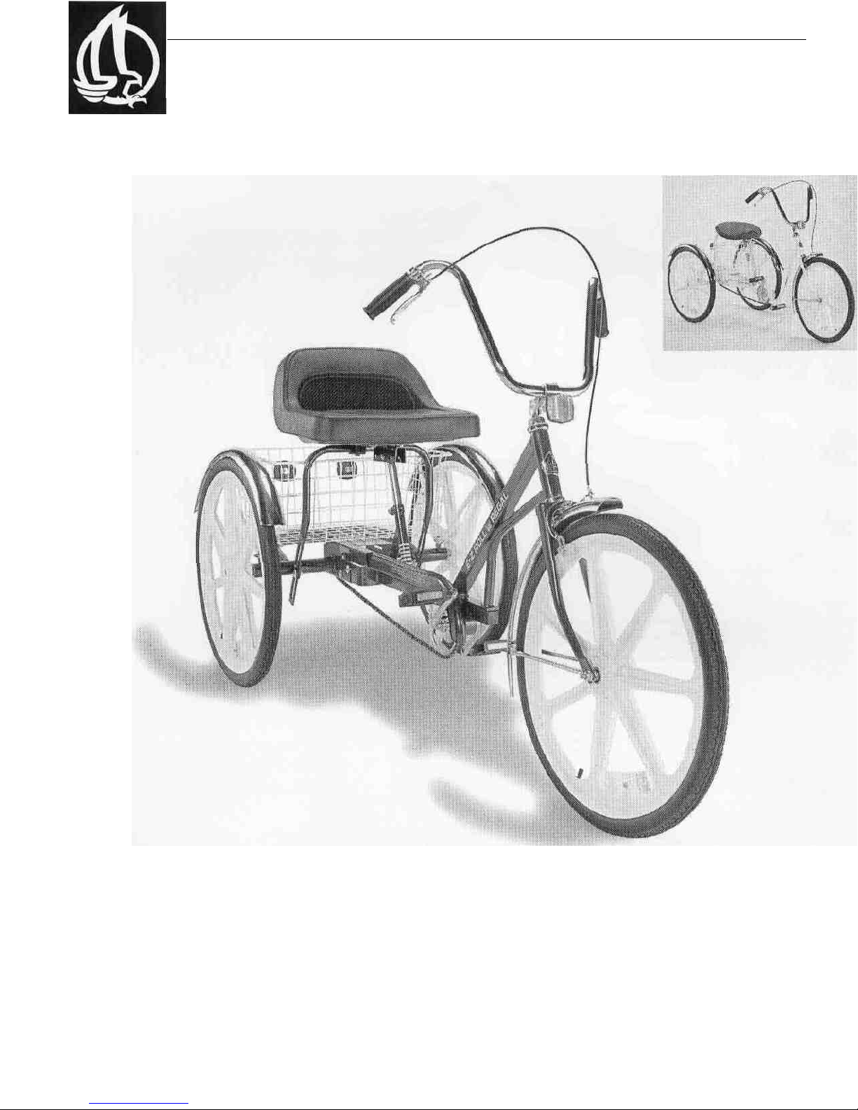
DeSOTO CLASSIC
and EZ ROLL REGAL
OWNER'S GUIDE


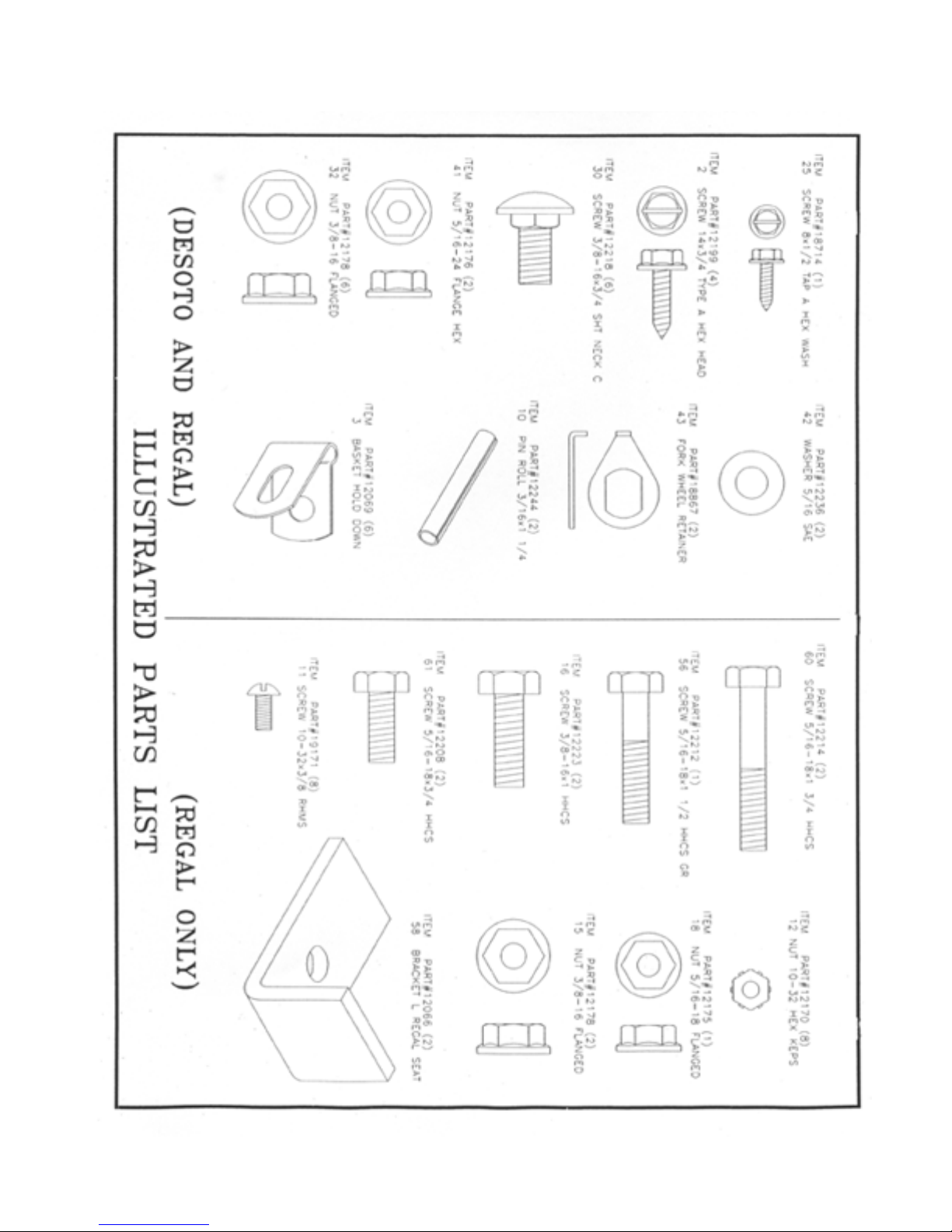
DESOTO/REGAL PARTS LIST
ITEM# PART* DESCRIPTION
QTY.
1 11871 REFLECTOR KIT, TRIKE 1
2 12199 SCREW#14x3/4 4
3 12069 BASKET HOLD DOWN 6
4 11639 BASKET 1
5 11626 AXLE, NON DRIVE 1
6 12241 SET COLLAR, 5/81.D. 2
7 11949 FREEWHEEL, 22T AND ADAPTER 1
8 12246 KEY SQUARE 3/16x1-1/14 1
9 11627 AXLE, DRIVE 1
10 12244 ROLL PIN 3/16x1-1/4 2
11 19171 SCREW#10-32x3/8RHMS 8
12 12170 NUT#10-32 8
13 11745 FENDER, 20" MWT REAR 2
11748 FENDER, 24" MWT REAR 2
14 19360 BRACE,20" REAR 4
19358 BRACE,24" REAR . 4
15 12178 NUT 3/8-16 FLANGE 8
16 12223 SCREW 3/8-16 x1 HHCS 2
17 11894 SEAT, WESTERN 1
18 12175 NUT 5/16-18 FLANGED 6
19 14272 FRAME, TRIKE REAR 1
20 11957 TIRE,20"x1.75"BSW 3
11961 TIRE, 24" x 1.75'BSW 3
11969 TIRE, 26'x 1.75" BSW 3
21 11970 TUBE, 20" x 1.75" 3
11976 TUBE, 24" x 1.75" 3
11978 TUBE, 26" x 1.75" 3
22 11984 RIMSTRIP, 20"x1.75" 3
11985 RIMSTRIP, 24" X 1.75" 3
11986 RIMSTRIP, 26" x 1.75" 3
23 12005 WHEEL, 20" x 1.75" X .080 REAR 2
12012 WHEEL, 24" x,1.75" x.080 REAR 2
18239 WHEEL, 24" x 1.75" x MAG REAR 2
24 18714 SCREW 8x1/2 PAN PHIL 1
25 11708 CHAINGUARD, DESOTO 1
11709 CHAINGUARD, REGAL 1
26 11857 PEDALS, 1/2" (PAIR) 1
27 13198 SCREW GROMMET 1
28 11643 BEARING SP 4
29 12218 CARRIAGE BOLT 3/8-16x3/4 6
30 12075 SISSY BAR, DESOTO 1
31 12178 NUT 3/8-16 6
32 12918 CHAIN, 109 PITCH 1/2x1/8 DESOTO 1
11682 CHAIN, 123 PITCH x 1/8 REGAL 1
33 142168 FRAME, DESOTO FRONT 1
34 11697 CRANK SET, COMPLETE 1
ITEM# PART#
35 11934 SPROCKET, 36T, 1/2 X 1/8
36 11694 CRANK, 4-1/2" (20" TRIKE)
11695 CRANK, 5-1/2" 124" & 26" TRIKE
37 11679 CONNECTING LINK
38 11743 FENDER, 20" MWT FRT. W/L-BR
11747 FENDER, 24" MWT FRT. W/L-BR
11752 FENDER, 26" MWT FRT. W/L-BR
39 11762 BRACE, 20" MWT
11764 BRACE, 24" MWT
11766 BRACE, 26" MWT
40 12176 NUT 5/16-24 HEX
19002 NUT 3/8-24 FLANGED
41 12236 WASHER 5/16 SAE
12301 WASHER 3/8 SAE
42 18867 AXLE RETAINER
43 12009 WHEEL, 20" x 1.75" X.080 FRONT
12016 WHEEL, 24" x1.75" x.080 FRONT
18240 WHEEL, 24" x 1.75"WH ITE MAG FRONT
12020 WHEEL, 26" x 1.75" x .080 FRONT
44 19338 BRAKE CANTILEVER MWT
45 14248 FORK, 20" MWT
19337 FORK, 24" MWT
19403 FORK, 26" MWT
46 11831 HEAD SET, COMPLETE
47 11805 HANDLEBAR, HI RISE
48 11801 GRIP BLACK 7/8
49 11813 STEM, HANDLEBAR
50 12188 SCREW 10x3/8 TYPE BSHH
51 13225 CLAMP BOLT M8x38MM
52 13226 CLAMP WASHER M8 FLAT
53 13227 CLAMP NUT M8 HEX
54 12076 SEAT POST 9"
55 12212 SCREW 5/16-18x1-1/2 HHCS
56 11898 BRACKET, WESTERN SADDLE
57 12066 BRACKET "L" REGAL
58 12070 SISSY BAR, REGAL
59 12214 SCREW 5/16-18x1-3/4 HHCS
60 12208 SCREW 5/15 -18 x 3/4 HHCS
61 12068 SEAT MOUNTING BRACKET REGAL
62 11900 SEAT, REGAL TRACTOR
63 14271 FRAME, REGAL MID
64 12211 CARR. BOLT 5/16-18x1-3/4
65 14270 FRAME, REGAL FRONT
66 11645 BRAKE CALIPER MWT
TRAILMATE owner's guide
OPTIONAL
ITEMS
OPTIONAL
OPTIONAL
OPTIONAL
OPTIONAL
OPTIONAL
OPTIONAL
OPTIONAL
OPTIONAL
TOOLS NEEDED
3/8" WRENCH
ADJUSTABLE WRENCH
COMMON SCREWDRIVER
AIR PUMP
1/2" WRENCH
PLIERS
PHILLIPS
SCREWDRIVER
AIR GAUGE
9/16'WRENCH 5/32"
ALLEN WRENCH
HAMMER DRIFT
PUNCH

DeSOTO CLASSIC & EZ ROLL REGAL
Assembly Instructions
1. Preparation
Remove all parts from the frame and wheel cartons.
Check tire air pressure and inflate to 35 psi. Make
sure tires are properly seated on rims.
2. Rear Frame and Wheels
Loosen set collar (6) from left rear axle and slide
axles (5 & 9) outward until the set collar and the
freewheel adapter (7) are against the inside axle
bearings; do not let freewheel adapter fall off. Insert
axle shaft into wheel (24) and secure with roll pin
(10). Please note that CB/ 3SPCB models use groove
pins in place of the roll pins. Be careful not to
damage spokes with hammer while installing roll
pins. Repeat procedure for both sides. If there is any
side-to-side movement of the axles, loosen set screw
in collars, slide axles and collars to eliminate excess
side movement, and retighten set screws. NOTE:
Install mag wheels with the steel collar facing the
inside of frame.
For coaster brake and three-speed coaster brake, see
"Installation Guide".
3. Front Frame
Slide front frame (34) into rear frame (19)
transmission box (open side down) as far as possible.
Install four 3/ 8" carriage bolts (30) through the slots
in the sides of the transmission box from the outside
inward. Be sure the square shoulders of the bolts seat
into each slot. Install flange nuts (32), but do not
tighten at this time.
4. Caliper Brake, Front
Fender and Wheel
Install front caliper brake (45) to front fork by inserting the
brake centerbolt through the holes in the front of the fork. Place
one contoured washer on each side of the fork. Before installing
nut, slide the fender bracket (39) over the centerbolt and secure
with washer and nut. Install front wheel in the slots in the fork.
Install axle retainers (43); make certain the tabs on the washers
are pointing upward and seated into the holes in the fork. Place
the fender braces onto each side of the wheel axle. After
checking that the wheel is centered evenly between the fork
blades, secure with washers (42) and nuts (41).
4a. Cantilever Brake, Front
Fender and Wheel
The front cantilever brake pad assembly comes at-
tached to the respective front fork. Unwrap the brake
cable and insert the "ball" end into the round slot in
the brake lever. Place the bezel (silver cap-type piece)
on the cable into the hole in the brake base (mounted
on the handlebar). Feed the cable through the cable
guide on the front of the fork. Thread the brake wire
through the cable clamp and snugly tighten the clamp
so that the hook portion of the clamp is facing the
wheel. Unwrap the cantilever brake cable and place
the ball end in the round slot in the cantilever brake.
Thread the cantilever brake cable through the hook
portion of the cable clamp and feed into the opposite
cantilever brake pad cable clamp. Pull the slack out of
the cable so that the cantilever brake pads are within
1/8" of the wheel. Snugly tighten the cantilever brake
pad cable clamp. Returning to the brake wire cable
clamp, pull the brake cable through the clamp until
the slack cable is removed and tighten the clamp.
5. Pedals
To install pedals (27), screw the pedal marked "R"
into the right side of the crank in a clockwise
direction. Install the left pedal (marked "L") by
turning in a counterclockwise direction. Use a 9/16"
open-end wrench to tighten.
6. Chain
Install drive chain (33) over front and rear sprockets
and join together with connecting link. Install
connecting link and spring clip (38) using pliers.
Slide the frame sections apart, evenly, until the chain
is tight (approximately 3/4" up and down movement
is permissible) and securely tighten all four rear
frame bolts. Rotate the pedals several times to check
that the chain is running freely - KEEP FINGERS
CLEAR! If binding is encountered, the chain may
have to be loosened until the binding is eliminated.
7. Chainguard
To install chainguard (26), place over chain and slide rear of
guard under top of transmission box. When the screw grommet
(28) on the rear of the guard is lined up with the slotted hole in
the side of the transmission box,
4 TRAILMATE owner's guide

DeSOTO CLASSIC & EZ ROLL REGAL
Assembly Instructions
Loosen the nuts on the brake pads and position pads
so they line up evenly with the rim. Tighten the brake
pad nuts securely. Working through the spokes (or
with a helper) squeeze the caliper pads tightly to the
rim. Pull the excess wire downward through the
drilled bolt and tighten the nut. DO NOT over tighten
as this can damage the cable. Release the caliper and
check the gap between the wheel and the pads. Apply
the brake several times to see that the pads engage the
rim tightly and evenly. To center the pads, if uneven,
loosen caliper mounting bolt (through fork),
reposition and re-tighten. To tighten pads further,
rotate the thumbscrew on the hollow bolt
counterclockwise (unthread) and lock in position with
lock nut. Lastly, place the protective cable and piece
over the end of the cable and crimp with pliers. This
will keep the cable from fraying and also protect the
sides from the sharp wire ends.
11. Reflectors
Install the red reflectors on the back of the basket. In-
sert the screw provided with the reflector through the
reflector clip and thread partially into the hole in the
back of the reflector. The open part of the arch in the
reflector clip should be facing the back of the
reflector. Place the reflector on the basket so the clip
will capture one of the vertical wires and tighten the
screw. Repeat for other side. The basket reflectors
should be about one foot apart.
* Steel Spoke Wheels-Install the clear wheel
reflectors by placing between the spokes, as near the
rim as possible. Locate the spoke groove on one side
of the reflector and place over one of the spokes.
Insert screw provided into this side and secure with
nut on other side. Make sure nut seals into reflector
recess before tightening; do not over tighten. Repeat
for other wheels.
* Plastic Mag Wheels -
Install reflectors on tabs using screw and nut.
12. Basket
Place basket (4) onto rear frame, centered between
the rear wheels and immediately behind the sissy bar.
Using holddown tabs (3) and sheetmetal screws (2),
secure the basket to the two holes in the rear frame
crossover tube and the two rear holes in the top of the
transmission box. Rotate the holddown tabs as neces-
sary to capture the wire of the basket in the indention
of the tab. Tighten screws with a 3/8" socket wrench.
13. Rear Fenders (Option)
To install rear fenders, first attach the fenders (13) to
the fender braces (14) with the four screws (11) and
nuts (12). DO NOT tighten at this time. NOTE: The
curved tops of the fender braces should point
outward. Attach fender braces to the tabs welded to
the top of the axle housing and secure with bolts (16)
and nuts (15). Before tightening, position fender over
top of wheel;
even-up both sides and tighten bolts. Lastly, position
fenders parallel to the tires and tighten screws and
nuts.
14. Final Check
Review the instructions, check connecting bolts and
screws for tightness, and readjust the seat and handle-
bar as necessary.
TRAILMATE owner's guide

Installation Guide
DeSoto/Regal Coaster Brake Kit # 12111
Check to make sure that you have all parts.
Parts Listing Qtv
1. 11066 Set Screws 2
2. 11667 TrikeCBHub 1
3. 11684 Rear Chain 1
4. 11939 Sprocket 21 Tooth Shimano 1
5. 11952 22 Tooth Solid Sprocket 1
6. 12170 Nut 10-32 Hex Keps 1
7. 12193 Screw 10-32x1 Phil Pan Hd MS 1
8. 12229 Washer #10 Flat 3
9. 12238 Hub Axle Spacers 3
10.12240 Rear Axle Spacers 7
11.16960 Dust Ring Shimano 1
12.16961 Snap Ring Shimano 1
13.18860 Solid Rear Wheel Pins 2
14. 19153 Nut Axle 2
15. Installation Instructions 2
NOTE:
DeSoto/ Regal Trikes w/ CB Hub Preinstalled in Frame
Proceed as follows:
'Skip over Kit Installation Preparation , Step 1 and Step 2.
Loosen hub axle nuts then proceed with Step 3 through Step 6.
Step I
Locate three hub axle spacer washers (9) from parts bag and install them onto axle on the side which has the brake arm. Then insert
hub into the open-ended L slot which is in the flat bar on the back end of the front frame. Refer to drawing for the location of hub axle
spacer washers and correct hub position.
Step 2
Loosen set collar on right side rear axle and remove original freewheel assembly and square key. Freewheel will no longer be needed,
but save key which will be needed to lock solid sprocket to axle. Locate six rear axle spacer washers (10) from parts bag and install
on right rear axle next to bearing. Install 22 Tooth solid sprocket (5) onto axle with set screws (1) on the same side as the spacer
washers. Reinstall square key and set collar. Tighten all set screws in place. Check that there is no sideways movement of rear axle in
bearings. If any is found, loosen set screws and reposition set collar and sprocket until it is eliminated.
Step 3
Slide rear frame over front frame. Let the Coaster Brake Hub axle slip into open-ended slots in the front of the transmission box.
Keep brake arm above rear axle tube while sliding frame sections together. Insert screw (7) to secure brake arm through slot in the
transmission box. Install washers (8) to fill space between box and brake arm, and then install brake arm nut (6). Do not tighten until
after chain is adjusted. Loosely install two of the frame bolts into transmission box.
Step 4
Install shortened front chain onto crank sprocket and outside sprocket on brake hub. Install rear chain (3) provided in parts bag around
sprocket on hub and solid sprocket on rear axle. Slide frame assembly apart until chains are tight. Tighten the frame nuts first, and
then after checking to make sure the hub is straight in frame tighten the axle nuts on brake hub. Tighten the nut and screw on the
brake arm. Install chainguard, spreading rear opening of guard enough to clear chains.
#18168 1/98
TRAILMATE owner's guide

Installation Guide
DeSoWRegaI 3-Speed Coaster Brake Kit #12115
Check to make sure that you have all parts.
Parts Listing QTY
1. 11066 Set Screws 2
2. 11684 Rear Chain 1
3. 11952 22 Tooth Solid Sprocket 1
4. 12170 Nut 10-32 Hex Keps 1
5. 12193 Screw 10-32x1 Phil Pan Hd MS 1
6. 12229 WasherS 10 Flat 3
7. 12240 Rear Axle Spacers 7
8. 12251 Hose Clamp 1
9. 12269 Cable Ties 4
10. 12285 Plastic Cable Stop S/A 1
11. 18049 Nut Axle S/A 1
12. 18860 Solid Rear Wheel Pins 2
13. 18909 Sprocket 2 IT S/A 1
14. 18913 Trike 3-spd CB Hub w/22 Spkt S/A 1
15. 18982 Snap Ring S/A 1
16. 18983 Dust Ring S/A 1
17. 18984 Washer Sprocket Spacer S/A 1
18. 18985 Nut Axle Right S/A 1
19. 18986 Hub Axle Antitum Washers S/A 2
20. 18993 Indicator Protector 1
21. 18995 Cable 3-Speed S/A 1
22. 18996 3-Speed Trigger S/A 1
23. 18997 Indicator Chain S/A 1
24. 18998 Adjusting Barrel S/A 1
25. Installation Instructions 3
Kit Installation Preparation
Remove chainguard. Remove front chain and remove the frame bolts in transmission
box and slide frame apart to expose L slot in front frame. Shorten front chain on
DeSoto to 93 pitch or shorten chain on Regal to 107 pitch.
Step 1
Install the 3-spd CB Hub (14) into the open-ended L slot which is on the back end of front frame. Refer to drawing for exact position of hub.
Step 2
Loosen set collar on right side rear axle and remove original freewheel assembly and square key. Freewheel will no longer be needed, but the save key square
will be needed to lock solid sprocket to axle. Locate seven rear axle spacer washers (7) from parts bag and install on right rear axle next to bearing. Install 22
Tooth solid sprocket (3) onto axle with set screws (1) on the same side as the spacer washers. Reinstall square key and set collar. Tighten all set screws in place-
Check that there is no sideways movement of rear axle in bearings. If any is found, loosen set screws and reposition set collar and sprocket until it is eliminated.
Step 3
Slide rear frame over front frame. Let the 3-spd Hub axle slip into open-ended slots in the front of the transmission box. Keep brake arm above rear axle tube
while sliding frame sections together. Insert screw (5) to secure brake arm through slot in the transmission box. Install washers (6) to fill space between box and
brake arm- and then install brake arm nut (4). Do not tighten until after chain is adjusted. Loosely install two of the frame bolts into transmission box. Place
antitum washers (19) onto each end of the axle on the outside of transmission box with tabs positioned into the slots in the frame. Loosely install axle nuts
(11,18) onto axle, refer to drawing for correct placement.
Step 4
Install shortened front chain onto crank sprocket and outside sprocket on brake hub. Install rear chain (2) provided in parts bag around sprocket on hub and solid
sprocket on rear axle. Slide frame assembly apart until chains are tight. Tighten the frame nuts first, and then axle nuts. Note: When tightening nuts, make sure
that the frame and hub is straight and not out of alignment. Tighten the nut and screw on the brake arm. Install chainguard, spreading rear opening of guard
enough to clear chains.
StepS
Install 3-speed trigger (22) onto right side of handlebar in front of brake lever clamp. Fasten plastic cable (10) stop to main frame tube with hose clamp (8).
Clamp should be 1 1/2" behind seat mast tube. Run cable (21) in front of trigger down along main frame and into plastic stop. Secure cable housing to tube frame
with cable ties (9).
Step 6
Refer to above drawing and Diagram 1 of Sturmey Archer Installation Instructions for connecting cable to hub and gear adjustment.
TRAILMATE owner's guide
NOTE:
PeSoto/Regal Trikes w/ 3-spd CB Hub Preinstalled in Frame
Proceed as follows:
• Loosen hub axle nuts then proceed with Step 3 through Step 6.

MAINTENANCE AND
INSPECTION
REGULAR MAINTENANCE: Bi-Monthly
1. Keep all painted parts cleaned and waxed for a long-lasting luster
2. Spray all chrome parts with recommended protective spray coating (LPS-1, WD-40, etc.). When spraying
with protective coatings, it is recommended that you let parts set overnight so the coating will penetrate.
3. Lubricate the following:
• Axle shafts
• Inside bearing of both pedals
• Chain - turn pedal crank forward and spray freely
4. When storing over prolonged periods, turn upside down to prevent flat spots from occurring on the tires. If
stored outside, cover to protect finish and moving parts.
PREVENTIVE MAINTENANCE: Every Six Months
These are services that should be performed by your local bicycle shop. A fee may be charged.
1. Check tires for wear, rim cuts and valve core alignment (usually caused by improper air pressure)
2. Check wheels for cracks and alignment.
3. Check brakes for proper operation
4. Clean and repack all bearings and adjust all cones
5. Check for worn bearings, cones and cups
6. Check chain for adjustment and clean as needed
7. Check for loose bolts and nuts.
Attention: While your unit is new, some noises may occur when the unit is breaking in. Should they
continue for more than 30 days, see you local bike shop.
INSPECTION
Check the following, as it applies to your cycle, on a regular basis:
1. Hand Brake: Make sure the brake engages, by squeezing the hand brake.
2. Wheels: Check wheels for alignment.
3. Pedals: Inspect pedal bearings and make sure pedal is tightly attached to crank.
4. Handlgrips: Replace worn or loose grips.
5. Chain: Check for proper tightness. Replace damaged chain immediately.
6. Seat: Adjust seat for rider comfort and safety.
7. Tires: Keep tires inflated to the recommended tire pressure, as indicated on the tire's sidewall.
8. Reflectors: Replace missing reflectors immediately.
9. Chainguard: Replace damaged or missing chainguard immediately
10. Frame: Replace damaged frame immediately.
TRAILMATE owner's guide 9

Trailmate Limited Warranty
Trailmate, Inc., guarantees each cycle product against all defects in materials and workmanship for
a period of 90 days from date of purchase. Tires and tubes are not covered by this guarantee.
During this period, any part that is judged by the makers to be defective will be replaced free of charge.
Any failure resulting from accident, abuse, neglect, normal wear, or improper assembly or maintenance by
the owner is not covered.
Trailmate, Inc., further authorizes a lifetime frame guarantee and will replace any frame, at no cost
to the buyer, providing that item has not been used for rental use and that:
1) The item has not been altered, repaired, or modified in any way.
2) The item has not been subject to misuse, negligence, and/or an accident.
3) Original ownership is established.
Any parts under this guarantee on which claims are entered shall be returned for inspection with
transportation charges prepaid by the claimant. Replacement parts will be shipped F.O.B. factory.
There are no warranties or guarantee, expressed or implied, written or oral, which extend beyond
the description on the face hereof.
#18234
2/00
TRAILMATE owner's guide
TRAILMATE
2359 Trailmate Drive
Sarasota FL 34243
(941)755-5511
Fax:(941)758-5141
For service or to order
replacement parts,
please contact your
local Trailmate dealer.
DeSOTO CLASSIC and
EZ ROLL REGAL
This is a recreational unit, not designed for excessive speeds or
misuse. Careless operation may cause rider to lose control and
result in serious injury.
Do not brake or turn at high speeds; this may cause cycle to roll-
over and rider injury.
Things to know before riding your cycle:
1. Know your local bicycle laws and wear a helmet
2. Do not exceed the recommended weight limit of 250 Ibs
3. No more than one rider at one time
4. Do not stand on unit
5. Be sure to install safety flags
6. Wear light-colored clothing and protective gear
7. Do not ride at night
8. Children must be supervised by an adult at all times
This manual suits for next models
1
Table of contents


