DE-STA-CO DirrectConnect DPE Series User manual
Product Specifications
Voltage 24 VDC
Power Max. 40 W
Operating Temperature 5° / 50° C (40° / 120°F)
Protection Class IP54
Clean Room 100
Clean Room with Scavenge Port* 10
*Contact Tech Support.
Maintenance Specifications
Field Repairable Yes
Application Restrictions
• Timing, power and load beyond specifications
• Suitable for external gripping only
Technical Specifications:
Gripper can be mounted and operated in any orientation
Mounting Information:
G
• Electrically Actuated
24 VDC, 4-wire input: power, ground, open & closed signals.
100% duty cycle for high throughput.
• “Light Switch” Simplicity
Plug and play. No programming, tuning or adjusting required.
As easy as a pneumatic gripper to control and operate.
• Energy Efficient
Only 3W required. Can be driven directly by most PLC’s
without a separate power supply. Can be battery driven
for remote applications.
• High Cycle Life
20+ million cycles with zero maintenance!
High reliability eliminates down time.
Lowest cost of ownership of any gripper,
pneumatic or electric.
• Built-in Electronics
All electronics are sealed
within the gripper. No external
control board needed.
4-pin/wire control cable
sold separately.
• Long Stroke, Fast Actuation
25mm stroke for picking multiple sized parts.
Full actuation in 0.25 second. Pick up to 150
parts per minute (with reduced stroke).
• Failsafe operation
In case of a power loss, the jaws will not
separate but grip force will be diminished.
Finger design should include features other
than just friction to retain part for critical
applications.
DPE Parallel Gripper-
Electric Gripper Series
Patent Pending.
Please see back cover for DE-STA-CO Global Locations. www.destaco.com
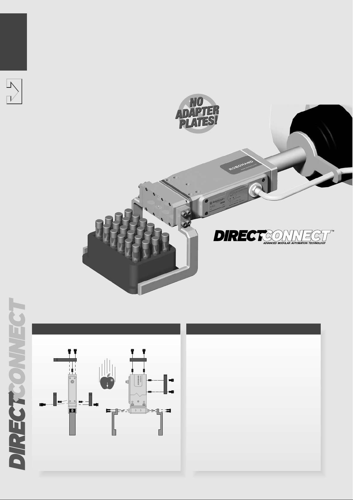
Body mounts with screws
and locates with slip fit
dowel pins for accuracy
Fingers attach to jaws
with screws and locate
with dowel pins
TM
1.8
DPE SERIES
1_8-1_13 DPE_(ENG_A4)_Layout 1 09.05.11 14:33 Seite 8

Product Features
• Apply +24 VDC from the PLC to the gripper “Close“ wire.
• The motor rotates a planetary gear reduction box that is connected to the drive
pinion by a coupling
• The pinion drives the integral jaw racks causing the jaws to close synchronously
• Power is maintained to the closed signal to continue gripping force throughout
the grip cycle.
• To open, remove signal to “Close” wire and apply +24 VDC from the PLC to the
gripper “Open“ wire
• Design is suitable for internal or external gripping
Style-DPE
Size -200-25
See
Page 1.10
Style: DPE-200-25
Stroke: 25 mm 0.98 in
Grip Force: 90 N 20 lbs
Weight: 0.53 Kg 1.16 lbs
Slip Fit Dowel
Pin Holes
Located in body and jaws
for precision mounting.
One-Piece Body
One-piece, lightweight aircraft
quality aluminum body ensures
product accuracy.
Hardcoat Anodize
The body and jaws are hard-
coat anodized to 60Rc with
Teflon impregnation.
Sealed Design
IP 54 rating for tough
application environments.
Superior Jaw
Support
Ridged design and full body
support of the jaws allows
for long finger lengths.
DirectConnect Mounting
Mounts directly to other automation
products without adaptor plates.
Versatile mounting on top, side front
and back of body.
Cover Cap
Motor + Gearbox
Coupling
Electronics
Jaw
Operating Principle
Body
Please see back cover for DE-STA-CO Global Locations. www.destaco.com
Patent Pending
Rack & Pinion Drive
Precision drive components for
smooth actuation. Zero backlash
while gripping ensures excellent
repeatability and accuracy.
Multiple Position Sensing
Slot mounted magneto-resistive sensing. Sense up
to 4 gripping positions. Internal magnetic targets
and external sensor mounting slots come standard.
Sensors & quick disconnect cables sold separately.
TM
1.9
DPE SERIES
1_8-1_13 DPE_(ENG_A4)_Layout 1 09.05.11 14:33 Seite 9
[1.62]
41.0
[5.039]
128.0
2.126
[54.0]
1.121
[28.5]
[.375]
9.5
38.1
[1.500]
2X
ØM5 [H7] X 6.2 DP
(NEAR & FAR SIDE)
2X M5 X 6.2 DP
56.0
[2.20]
CLOSED AS SHOWN
81.0
[3.19]
OPENED
38.10
(DOWEL)
[1.5000]
38.1
[1.500]
38.10
(DOWEL)
[1.5000]
38.1
[1.500]
38.10
(DOWEL)
[1.5000]
[.75]
19.1
4X M5 X 10.0 DP
2X M5 (H7) X 6.4 DP
[.75]
19.0
A
[.472]
12.0
[.236]
6.0
[.472]
12.0
[.787]
20.00
[.6299]
16.00
4X M3 X 6DP
2X
Ø2[H7] X 6 DP
DETAIL A
(JAW FEATURES-FINGER MOUNT)
4X M5 X 0.8 X 10.0 DP
2X
ØM5 [H7] X 6.2 DP
19.1
[.750]
[.95]
24.2
[4.685]
119.0
[1.102]
28.0
M8X1 MALE
(CABLE SOLD
SEPARATELY)
C
L
C
L
C
L
C
L
C
L
C
L
C
L
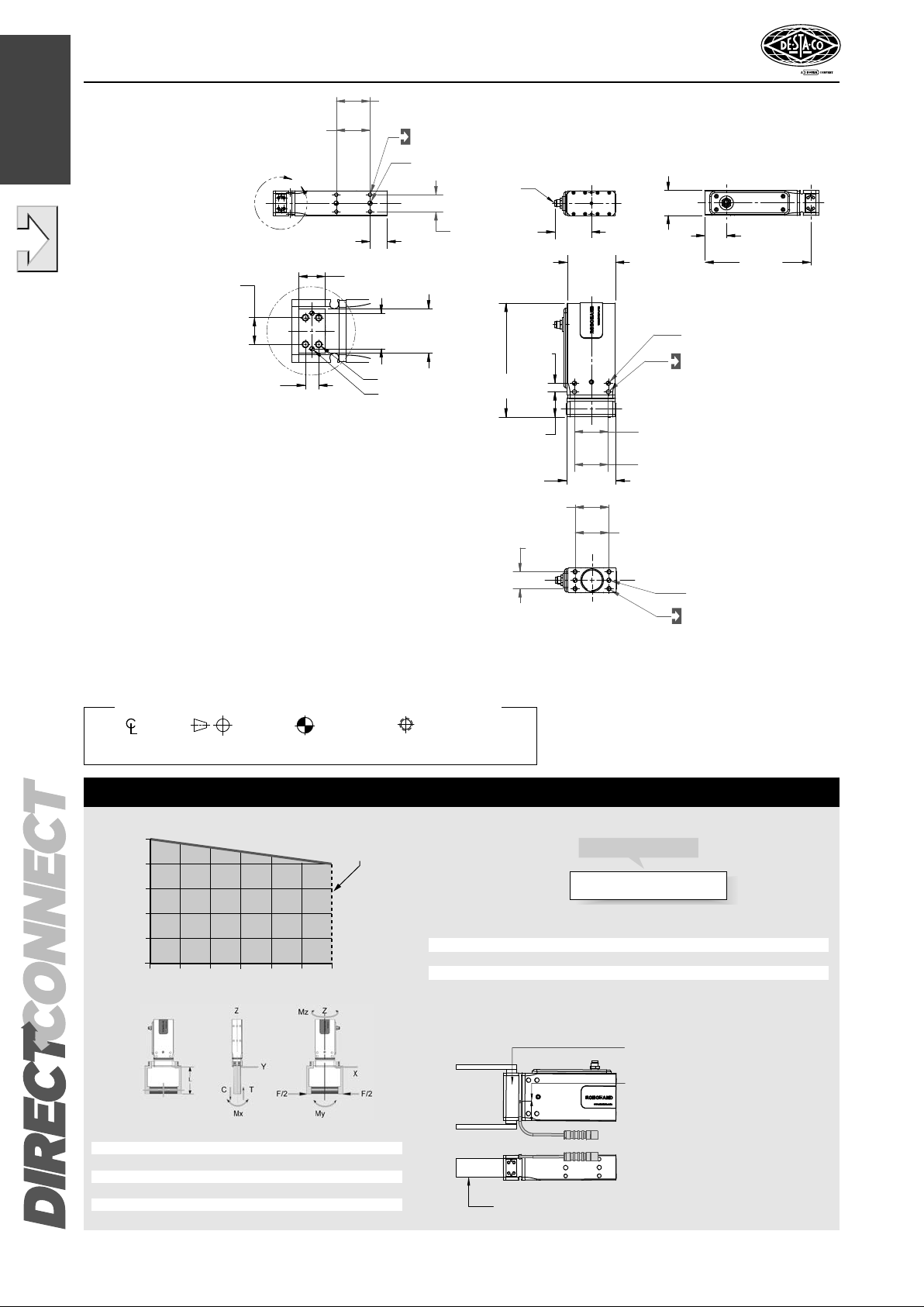
PARALLEL GRIPPER DPE-200-25
E-GRIPPER SERIES
How to Order: (Order Accessories separately from Basic Model)
DPE-200-25
BASIC MODEL
Loading Information
Loading Capacity†Static
Maximum Tensile T75 lbs [10 N]
Maximum Compressive C75 lbs [10 N]
Maximum Moment Mx120 lbf-in [14 Nm]
Maximum Moment My150 lbf-in [17 Nm]
Maximum Moment Mz120 lbf-in [14 Nm]
†Capacities are per set of jaws and are not simultaneous
44
35
16
18
9
0
N
10
8
6
4
2
0
lbs.
EFFECTIVE FINGER LENGTH - L
FINGER FORCE - F/2
FORCE VS LENGTH
0 0.5 1.0 1.5 2.0 2.5 3. 0 in.
0 13 25 38 51 64 76 mm
WARNING!
DO NOT EXCEED
MAXIMUM EFFECTIVE
FINGER LENGTHS
Third Angle
Projection
Dimensions are
symmetrical about
centerline
Metric [mm]
[0.] = [±.25]
[0.0] = [±.13]
[0.00] = [±.013]
All Dowel Holes are SF (Slip Fit).
Locational Tolerance ±.013mm
UNLESS OTHERWISE NOTED ALL TOLERANCES ARE AS SHOWN BELOW
Metric Threads
Course Pitch
ACCESSORIES*
4-wire Power and Signal Cable, 5m long CABL-046 1
NPN Magneto Resistive Sensor OHSN-017 1 or 2
PNP Magneto Resistive Sensor OHSP-017 1 or 2
Quick Disconnect 5 Meter Cable Length* CABL-013 1 or 2†
*Sensor and cables sold separately. †Power cable plus 1 or 2 sensor cables.
Specifications DPE-200-25
Maximum Finger Length . . . . . . . . 76.2 mm (3.00 in)
Stroke . . . . . . . . . . . . . . . . . . . . . . . 25 mm (0.98 in)
Gripping Force in Closing . . . . . . . . 90 N (20 lbs)
Closing Time/Opening Time . . . . . . 250 ms (250 ms)
Repeatability . . . . . . . . . . . . . . . . . . ± 0.025 mm (0.001 in)
Accuracy . . . . . . . . . . . . . . . . . . . . . ± 0.051 mm (0.002 in)
Voltage . . . . . . . . . . . . . . . . . . . . . . 24 VDC
Power Req. @ 100% Duty Cycle . . 3 Watts
Current - Peak . . . . . . . . . . . . . . . . 0.5 Amps Max.
Current - Continuous . . . . . . . . . . . . 0.125 Amps
Min./Max Operating Temperature . . 5° / 60° C (40° / 140° F)
Protection Class . . . . . . . . . . . . . . . IP54
Clean Room . . . . . . . . . . . . . . . . . . 100
Clean Room with Scavenge* . . . . . 10
Weight . . . . . . . . . . . . . . . . . . . . . . 0.53 Kg (1.16 lbs)
*Contact Tech Support.
INSTALL MAGNET HEAD INTO THE SLOT,
ADJUST IT'S LOCATION, AND LOCK ITS
POSITION WITH THE PROVIDED
LOCK SCREW.
SENSOR TARGET SUPPLIED
INSIDE WITH THE JAWS
CUSTOMER SUPPLED FINGER
Please see back cover for DE-STA-CO Global Locations. www.destaco.com
TM
1.10
DPE SERIES
1_8-1_13 DPE_(ENG_A4)_Layout 1 09.05.11 14:33 Seite 10

PARALLEL GRIPPER DPE-200-25
E-GRIPPER SERIES
Installation and Operation:
1. Mount fingers (customer supplied) to gripper jaws using dowel pins and threaded fasteners. See dimensional drawing for hole sizes.
Use Loctite®242 threadlocker or equivalent.
2. Mount gripper using dowel pins and threaded fasteners. Gripper can be mounted and operated in any orientation. See dimensional drawing
for mounting hole pattern and sizes. Use Loctite® 242 threadlocker or equivalent.
3. To operate the DPE gripper, follow the instructions below:
Apply +24VDC to pin 1 (brown) and Ground to pin 3 (blue) to turn on the gripper. To open the fingers, apply +24VDC to pin 2 (white).
To close the fingers, remove +24VDC from pin 2, and apply +24VDC to pin 4 (black). +24VDC signal must remain present on the open / close
line to maintain the force output. The gripper will do nothing if a +24VDC signal is present on the open and close lines at the same time.
WARNING:
• Operating gripper outside of power voltages and can cause damage and void warranty
• Disconnect power from gripper before performing maintenance or making adjustments.
PIN OUT
(LOOKING INTO HEADER CONNECTOR ON GRIPPER)
1 ........ BROWN
2 ........ WHITE
3 ........ BLUE
4 ........ BLACK
(+ 24 VDC)
(OPEN GRIPPER) +24 VDC = ACTIVE
(GROUND)
(CLOSE GRIPPER) +24 VDC = ACTIVE
CABLE # CABL-046
ELECTRICAL INTERFACE
2
43
1
Please see back cover for DE-STA-CO Global Locations. www.destaco.com
TM
1.11
DPE SERIES
1_8-1_13 DPE_(ENG_A4)_Layout 1 09.05.11 14:33 Seite 11

12 35
7
8
9
32
10
15
33
16
17
18
21
24
20 22
23
4
19
21
2715
28
25
25
28
30
31
29
6
711
12
13
1
14
26 Will be installed
above the cover
Item Qty Name
01 1 Body
02 1 Bottom Plate
03 1 Cap
04 1 Cover
05 2 Bumper
06 2 Jaw
07 2 Coupling Pin
08 1 Drive Pin
09 1 Motor Control Board
10 1 Coupling Insert
11 2 Tag-Destaco-Robohand
12 1 Tag-Electric Pin Out
13 1 Tag-Production
14 1 Tag-VBL Collar
15 2 Magnet
16 1 Bearing
17 8 SHCS, M1.6*5mm, Alloy
18 3 SHCS, M2.5*5mm, Alloy
19 1 Dowel Pin: 1/8 Dia X 3/8
20 2 Dowel Pin: 2mm
dia*6mm lg
21 8 Screw, Fillister HD,
M2x6mm
22 2 Dowel Pin: 3mm
dia*6mm lg.
23 0 Jam Nut-Ref Only (Part Of
Motor Control Board)
24 8 Washer
25 2 Set Screw
26 0 O-Ring - Ref Only (Comes
With Connector)
27 1 O-Ring
28 2 Set Screw
29 1 O-Ring
30 1 Set Screw
31 4 O-Ring, Buna, 70d,
0.026 CS, .097id
32 1 Gear Motor
33 1 Ret. Ring
NOTE: Contact the DE-STA-CO Customer
Service for a complete spare parts list
with order numbers and prices.
Assembly Procedure
1) Clean all make details free of dirt, oil and
other contaminants.
2) Insert # 32 motor into the # 1 body, line up
the motor holes and assemble motor to the
body by using # 18 screws. Make sure that
the motor wires are carefully routed to the top
for it's
connection to the motor control board.
3) Assemble # 25 set screws one of the # 7
coupling hubs, but not all the way in. Assem-
ble the coupling to the motor shaft, with flat
on the motor shaft facing one of the set
screws and adjust the inside face of the cou-
pling, flat with end face of the motor shaft.
Tighten the set screw on the motor shaft thru
the acccess
hole at set screw # 30 location.
4) Assemble the # 10 coupling insert into the
# 7 hub, as asssembled to the motor shaft,
as above.
5) Assemble # 8 drive pinion with it's shaft all
the way into the second # 7 coupling hub and
tighten the set screws. Assemble # 16 bear-
ing and # 19 dowel pin into the drive pinion.
Now install this assembly hub / insert as-
sembly installed earlier to the motor shaft.
7) Assemble # 15 magnets into # 6 jaws,
using lok-tite as recommended.
8) Lubricate the pinion, the bearing, the jaws
and inside surfaces of jaw-ways with lubri-
cant as recommended.
9) Install the jaws into the body, meshed with
the pinion and symmetrically positioned w.r.t
the pinion.
10) Install # 5 stop and # 22 dowel pins into
the jaws.
11) Assemble # 2 cover to the body, with dowel
pins # 19 and # 29 aligned to the cor-
rosponding holes in the cover. Install fasten-
ers # 17 to secure the cover to the body.
12) Install / connect the motor cable connector
the motor control board. Use # 21 & # 24
fasteners and install the motor control board
to the body. Note: Remove the hex nut sup-
plied with the connector on the motor con-
trol board.
This hex nut will be re-installed after # 4
cover is installed.
13) Install # 4 cover to the body with # 29 gas-
ket and # 21 screws as shown.
14) Installed the previously removed hex nut
back to the connector. Caution: Only snug
tighten this hex nut.
15) Install # 3 cap with O ring and snap ring,
as shown.
16) Install tags and labels as shown.
DPE SERIES EXPLODED VIEW
Please see back cover for DE-STA-CO Global Locations. www.destaco.com
TM
Third Angle
Projection
Seal Kit
Items
Thread
Locker
Krytox™
Lubricant
Teflon™Based
Grease
Lightweight
Machine Oil
Super
Bonder
SK
KRYTOX
KRYTOX
1.12
DPE SERIES
1_8-1_13 DPE_(ENG_A4)_Layout 1 09.05.11 14:33 Seite 12

Third Angle
Projection
Seal Kit
Items
Thread
Locker
Krytox™
Lubricant
Teflon™Based
Grease
Lightweight
Machine Oil
Super
Bonder
SK
KRYTOX
KRYTOX
1
2
5
4
3
7
6
8
Item Qty Name
01 1 Body
02 2 Jaw
03 1 Motor/Gear ASM
04 1 Coupling Asm
05 1 Pinion
06 1 Bearing
07 1 Motor Control Board
84 1 End Cap
NOTE: Contact the DE-STA-CO Customer
Service for a complete spare parts list with
order numbers and prices.
DPE SERIES EXPLODED VIEW
Please see back cover for DE-STA-CO Global Locations. www.destaco.com
TM
1.13
DPE SERIES
1_8-1_13 DPE_(ENG_A4)_Layout 1 09.05.11 14:33 Seite 13
This manual suits for next models
1
Table of contents


