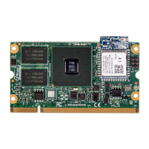
DEBIX Model A User manual

Polyhex Technology Co., Ltd.
1/108
www.debix.io
DEBIX User Manual
Version: V2.5 (2023-03)
Editor: Polyhex Technology Company Limited (http://www.polyhex.net/)
In recent years, with the ever-increasing product demand in fields of application such as
smart home, smart security, video surveillance and industrial automation, AI chips capable of
resolving problems in these fields have also emerged. Polyhex Technology has responded to
this demand with the launch of DEBIX, a development board based on NXP NPU processor
i.MX 8M Plus. It focuses on machine learning, vision processing, and industrial IoTs, meeting
the application needs of commercial and industrial fields such as education, security
monitoring, industrial automation, smart homes and smart cities.
Figure 1

Polyhex Technology Co., Ltd.
2/108
www.debix.io
INDEX
Chapter 1 About DEBIX ..............................................................................................................4
DEBIX Structure Overview ..................................................................................................5
DEBIX Tech Specs .............................................................................................................. 7
DEBIX I/O Interfaces ........................................................................................................... 8
Display Interface ................................................................................................................12
HDMI Interface ........................................................................................................... 12
LVDS Interface ............................................................................................................13
DSI Interface ...............................................................................................................16
Chapter 2 DEBIX Installation Guide .........................................................................................18
Hardware Installation .........................................................................................................20
Insert Micro SD card ...................................................................................................20
Connect the display device ........................................................................................ 20
Connect the keyboard and mouse ............................................................................. 21
Connect the network cable .........................................................................................21
Connect the power adapter ........................................................................................21
Software Installation .......................................................................................................... 22
Boot from the Micro SD card ......................................................................................22
Boot from eMMC ........................................................................................................ 23
Chapter 3 Using DEBIX ............................................................................................................27
Desktop Introduction ......................................................................................................... 27
System Browser ................................................................................................................ 28
File Management ...............................................................................................................28
First Time Use ................................................................................................................... 29
Change User Password .................................................................................................... 30
Wi-Fi Connection ............................................................................................................... 30
Change Language .............................................................................................................31
Setting up Access Point .....................................................................................................33
Shut Down ......................................................................................................................... 34
The three screens supported by DEBIX ........................................................................... 35
Use lidar module on DEBIX .............................................................................................. 44
Chapter 4 Introduction of Hardware Programming .................................................................48
GPIO Introduction ..............................................................................................................48
Usage of GPIO .................................................................................................................. 50

Polyhex Technology Co., Ltd.
3/108
www.debix.io
Chapter 5 DEBIX I/O Board ..................................................................................................... 53
Brief Introduction of DEBIX I/O Board ...............................................................................53
Interface Definition .............................................................................................................53
Connection with DEBIX Model A .......................................................................................55
DIP Switch Introduction ..................................................................................................... 61
CAN/RS485/RS232 ...........................................................................................................64
Usage of Type-C Debug ....................................................................................................69
Usage of CSI Camera ....................................................................................................... 73
Camera Interface Verification ............................................................................................75
Usage of DSI Display ........................................................................................................ 75
Usage of RTC .................................................................................................................... 78
Usage of LAN2 .................................................................................................................. 80
Usage of Raspberry Pi POE HAT ..................................................................................... 81
Chapter 6 DEBIX LoRa Board ................................................................................................. 85
Brief Introduction of DEBIX LoRa Board ...........................................................................85
Interface Definition .............................................................................................................85
Connection with DEBIX Model A .......................................................................................86
Verify Functions of LoRa Board ....................................................................................... 89
Chapter 7 DEBIX 4G Expansion Board ................................................................................... 91
Brief Introduction of DEBIX 4G Expansion Board ............................................................ 91
Interface definition ............................................................................................................. 91
Connection with DEBIX Model A .......................................................................................92
First use of 4G network ..................................................................................................... 96
Common Troubleshooting ............................................................................................... 104
Chapter 8 DEBIX PoE Module ...............................................................................................105
Brief Introduction of DEBIX PoE Module ........................................................................ 105
Interface definition ........................................................................................................... 105
Connection with DEBIX Model A/B ................................................................................. 106
Usage of PoE Module ..................................................................................................... 108

Polyhex Technology Co., Ltd.
4/108
www.debix.io
Chapter 1 About DEBIX
DEBIX is essentially a versatile single board computer, which can be widely used in artificial
intelligence, machine learning, industry 4.0, edge computation, gateway, IoT, security
monitoring etc..
The following are some of the powerful features of DEBIX:
●Powerful Quad Core Arm ® Cortex ® -A53 CPU with a Neural Processing Unit (NPU)
operating at up to 2.3 TOPS.
●The multimedia capabilities include video encode (including h.265) and decode,
3D/2D graphic acceleration, and multiple audio and voice functionalities.
●Real-time control with Cortex-M7. Robust control networks supported by dual CAN
FD and dual Gigabit Ethernet with Time Sensitive Networking (TSN).
●High industrial reliability with DRAM inline ECC.
●Designed for severe environmental conditions and industrial grade temperature
requirements. The wide CPU temperature range of -40°C to 105°C makes it suitable
for extreme operation environments like public transportation and industrial control
etc.
●The size of the board is nearly the same with a credit card, it has multiple extended
ports. This allows DEBIX to give full processor performance while being free from
application restrictions in physical space.
●Support mainstream operating systems including Android, Ubuntu, Yocto and
Windows 10 IoT.
DEBIX has a clear edge in the area of facial and object recognition applications which
combine machine learning and visual processing. Take facial recognition as an example:
DEBIX can simultaneously detect and identify the body frames and facial features of multiple
people. It can also be used in traffic control to identify vehicle types and information of drivers.
Using NPU to perform recognition operations not only increases the recognition speed, but
also sees a noticeable reduction to the burden on the CPU.

Polyhex Technology Co., Ltd.
5/108
www.debix.io
DEBIX’s TSN technology makes it essential for Industrial 4.0 applications, as it meets the
needs of industrial enterprises with precision oriented production time control, thus
increasing the interconnection speed of the IoT.
DEBIX Structure Overview
DEBIX's interface features a compact arrangement, the interface components are visible at a
glance. Let’s learn more about DEBIX’s interface through the following Figure 2.
Figure 2
Figure 3

Polyhex Technology Co., Ltd.
6/108
www.debix.io
DEBIX uses NXP i.MX 8M Plus based SoC, it has 2GB/4GB/6GB/8GB memory, supports
Gigabit Ethernet, dual-band wireless network and Bluetooth 5.0. The data specifications are
as below:
System
CPU
NXP i.MX 8M Plus (default), 4 x Cortex-A53, comes with an integrated
neural processing unit (NPU) that delivers up to 2.3 TOPS. Industrial
grade CPU runs at 1.6GHz, and commercial grade CPU runs at up to
1.8GHz. (i.MX 8M Plus series CPU optional)
with C520L 3D GPU andGC7000UltraLite 3D GPU
Memory
2GB LPDDR4 (4GB/6GB/8GB optional)
Storage
Default: Micro SD card(The Micro SD card should be prepared by the
users themselves, the capacity can be 8GB/16GB/32GB/64GB/128GB)
(Onboard 8GB/16GB/32GB/64GB/128GB eMMC optional)
Operating System
Android 11, Ubuntu 20.04, Yocto-L5.10.72_2.2.0, Windows 10 IoT
Enterprise
I/O Interfaces
Gigabit Network
10/100/1000M 2 Ethernet interfaces
1 x RJ45 with POE power supply (need POE power supply
module)
1 x pin header (without network transformer)
WIFI & BT
2.4G & 5G dual-frequency WIFI, BT5.0
USB
4 x USB 3.0 Host Type-A, 1 x USB 2.0 OTG Type-C
Audio
1 x 3.5mm headphone and composite microphone port
HDMI
1 x HDMI OUT
Expansion
40-Pin Double-Row
Headers
(1) 3 x UART, 2 x SPI, 2 x I2C, 2 x CAN, 1 x PWM, 2 x GPIO, dedicated
interfaces can be reused as GPIO ports
(2) 1 x SPDIF digital audio input/output
(3) 5V power supply, system reset, ON/OFF
LVDS
1 x LVDS, single & dual channel 8bit, double-row pin headers
MIPI CSI
1 x MIPI CSI, support 4-lane, 24Pin 0.5mm Pitch FPC socket
MIPI DSI
1 x MIPI DSI, support 4-lane, 24Pin 0.5mm Pitch FPC socket
PCIe
1 x PCIe, support PCIe x1, 19Pin 0.3mm Pitch FPC socket

Polyhex Technology Co., Ltd.
7/108
www.debix.io
Power Supply
Power Supply
DC 5V/3A Type-C
Mechanical & Environmental
Size
85.0mm x 56.0mm
CPU Temperature
-40 ˚ C to 105 ˚ C
DEBIX Tech Specs
Figure 4
Like any standard computer, DEBIX consists of a range of different computer components.
The most important component is the "brain" of the computer, the system-on-chip/SoC in the
center at the front of the motherboard.
The SoC contains most of the components of the computer, often containing both the central
processing unit (CPU) and the graphics processing unit (GPU). Next to the SoC you will find
another larger chip, the random access memory (RAM).

Polyhex Technology Co., Ltd.
8/108
www.debix.io
Figure 5 CPU&GPU Figure 6 RAM
There is a component with a metal cover in the upper left corner of the motherboard, it
contains the wireless communication module which contains the wireless network card and
Bluetooth components.
Figure 7
The eMMC is in the right down direction of WIFI & BT, it integrates a controller in its
enclosure, provides standard interfaces and manage the flash. The PMIC(PCA9450c) is in
the right down corner of the motherboard, it manages the power devices of the host machine.
DEBIX I/O Interfaces
DEBIX has 4 USB3.0 Host A ports, they are all USB3.0 interfaces. The Ethernet port is on
the right side of the USB 3.0, it connects DEBIX to the network through a cable with an RJ45
connector. There are two status indicators below the Ethernet port to show the signal
upstream or downstream status, one is Link, the other is Active:

Polyhex Technology Co., Ltd.
9/108
www.debix.io
Figure 8
There is a 3.5mm headphone interface with audio input/output function on the edge of the
board. Next to the headphone interface, there is a Type A HDMI connector for connecting a
display device, TV or projector. On the left side, there is a multifunctional OTG port for
programming, system updating, or USB drive & hard disk connecting etc. Next to the OTG
interface is the USB Type-C power port for DEBIX power supply. We recommend using a
5V/3A power adapter to ensure sufficient power supply.
Figure 9
Next to the OTG port is the CSI connector for camera module connection. There is also a
DSI connector for MIPI touch screen connection.
Figure 10
The 40-pin GPIO connectors on one side of DEBIX are for external hardware connections
such as LEDs, buttons, sensors, and functional modules, among the 40 pins, the 4 pins on
the right side of the 40 pins are called POE (Power Over Ethernet) connectors.

Polyhex Technology Co., Ltd.
10 /108
www.debix.io
Figure 11
U77410n0der the GPIO pins, there are two connectors, the right side connector J6 is 2x6Pin
LAN pins for connecting to the local network, the left side connector J10 is 2x15Pin LVDS
pins, it is a LVDS display output interface, it support single channel and dual channel LVDS
display.
Figure 12

Polyhex Technology Co., Ltd.
11 /108
www.debix.io
The Micro SD card slot is on the back of the motherboard. Insert the Micro SD card with the
installed system in the slot, and then power it up to boot.
There is a connector beside the Micro SD card slot. The J18 connector is a 19Pin PCIe pin,
which can be used to connect some independent accessories, such as PCIe to USB.
PCIe connector is FH26W-19S-0.3SHW(97). please refer to FH26W-19S-0.3SHW(97) on
website https://www.debix.io/. The corresponding wire material shall meet the above connector
interface requirements.
Figure 13
PCIe interface pins are defined as follows:
Pins
Definition
CPU PAD/Pin
1
VDD_3V3
-
2
VDD_5V
-
3
VDD_1V8
-
4
GND
-
5
GND
-
6
GND
-
7
SAI2_MCLK
AJ15
8
SAI2_RXFS
AH17
9
SAI2_RXC
AJ16
10
GND
-
11
PCIE_CLKN
E16
12
PCIE_CLKP
D16
13
GND
-
14
PCIE_TXN
B15
15
PCIE_TXP
A15
16
GND
-
17
PCIE_RXN
B14
18
PCIE_RXP
A14
19
GND
-

Polyhex Technology Co., Ltd.
12 /108
www.debix.io
Display Interface
i.MX 8M Plus supports the following displays:
One LCDIF driver for MIPI DSI, Up to UWHD and WUXGA
One LCDIF driver for LVDS Tx, Up to 1920x1080p60
One LCDIF driver HDMI Tx, 4kp30
When less than or equal to 2 LCD interfaces are used at the same time, each LCD interface
supports 1920x1200p60 display. When 3 LCD interfaces are used at the same time, it
supports 2 1080p60 + HDMI 4kp30.
HDMI Interface
DEBIX Model A has an HDMI connector (J9) at the lower right. The connector is a type A
HDMI mother base, which is used to connect the display, TV or projector.
Figure 14

Polyhex Technology Co., Ltd.
13 /108
www.debix.io
The supported HDMI resolutions are as follows:
740x480p60, 720x480p60, 1280x720p60, 1920x1080p60, 1920x1080p120,
3840x2160p30.
The pin sequence is as shown in the figure:
Figure 15
The HDMI interface is defined as follows:
Pins
Definition
Pins
Definition
1
HDMI-TXP2
2
GND
3
HDMI-TXN2
4
HDMI-TXP1
5
GND
6
HDMI-TXN1
7
HDMI-TXP0
8
GND
9
HDMI-TXN0
10
HDMI-TXCP
11
GND
12
HDMI-TXCN
13
PORT_CEC
14
HDMI_Utility_CN
15
DDC_SCL
16
DDC_SDA
17
GND
18
VDD5V
19
HDMI_HPD_CN
20
GND
21
GND
22
GND
23
GND
LVDS Interface
The LVDS display bridge (LDB) connects the LCDIF inside the CPU with the external LVDS
display device. The purpose of the LVDS display bridge (LDB) is to transmit synchronous
RGB data to an external display device through the LVDS interface.
The LVDS interface is used for the following:

Polyhex Technology Co., Ltd.
14 /108
www.debix.io
1.Single channel (4 lanes) 80MHz pixel clock and LVDS clock output. It supports resolutions
up to 1366x768p60.
2.Asynchronous dual channel (8 data, 2 clocks). This is for a screen with two interfaces,
which are transmitted through two channels (odd pixel/even pixel). It supports pixels higher
than 1366x768p60 and up to 1080p60.
The left tag J10 connector of GPIO connector of DEBIX Model A is 2x15Pin, which is an
LVDS display output interface and supports single or dual LVDS display.
Figure 16
The pin sequence is shown in the figure:
Figure 17

Polyhex Technology Co., Ltd.
15 /108
www.debix.io
The interface is defined as follows:
Pins
Definition
Description
1
VDD_LVDS
Default 5V(3.3V,5V,12-36V optional)
2
VDD_LVDS
Default 5V(3.3V,5V,12-36V optional)
3
VDD_LVDS
Default 5V(3.3V,5V,12-36V optional)
4
GND
To Ground
5
GND
To Ground
6
GND
To Ground
7
LVDS0_TX0_N
LVDS0 Differential data channel 0(-)
8
LVDS0_TX0_P
LVDS0 Differential data channel 0(+)
9
LVDS0_TX1_N
LVDS0 Differential data channel 1(-)
10
LVDS0_TX1_P
LVDS0 Differential data channel 1(+)
11
LVDS0_TX2_N
LVDS0 Differential data channel 2(-)
12
LVDS0_TX2_P
LVDS0 Differential data channel 2(+)
13
GND
To Ground
14
GND
To Ground
15
LVDS0_CLK_N
LVDS0 Clock differential signal path(-)
16
LVDS0_CLK_P
LVDS0 Clock differential signal path(+)
17
LVDS0_TX3_N
LVDS0 Differential data channel 3(-)
18
LVDS0_TX3_P
LVDS0 Differential data channel 3(+)
19
LVDS1_TX0_N
LVDS1 Differential data channel 0(-)
20
LVDS1_TX0_P
LVDS1 Differential data channel 0(+)
21
LVDS1_TX1_N
LVDS1 Differential data channel 1(-)
22
LVDS1_TX1_P
LVDS1 Differential data channel 1(+)
23
LVDS1_TX2_N
LVDS1 Differential data channel 2(-)
24
LVDS1_TX2_P
LVDS1 Differential data channel 2(+)
25
GND
To Ground
26
GND
To Ground
27
LVDS1_CLK_N
LVDS1 Clock differential signal path(-)
28
LVDS1_CLK_P
LVDS1 Clock differential signal path(+)
29
LVDS1_TX3_N
LVDS1 Differential data channel 3(-)

Polyhex Technology Co., Ltd.
16 /108
www.debix.io
30
LVDS1_TX3_P
LVDS1 Differential data channel 3(+)
DSI Interface
Key features of MIPI DSI include:
The commonly used MIPI DSI resolutions are supported as follows:
1080 p60, WUXGA (1920x1200) at 60 Hz, 1920x1440 at 60 Hz, UWHD (2560x1080) at
60 Hz
Maximum resolution up to WQHD(2560x1440), it depends on bandwidth between input
clock (video clock) and output clock (D-PHY HS clock)
The MIPI-DSI interface (J13) of DEBIX Model A can be used to connect the MIPI display
touch screen, as follows: the connector is 2 * 10Pin/1.25mm pin base.
Figure 18
The pin sequence is as shown in the figure:
Figure 19

Polyhex Technology Co., Ltd.
17 /108
www.debix.io
The interface is defined as follows:
Pins
Definition
Description
1
VDD_5V
5V input
2
VDD_3V3
3.3V input
3
VDD_1V8
1.8V input
4
DSI_BL_PWM
Backlight control signal
5
DSI_EN
LCD enable signal
6
DSI_TP_nINT
touch interrupt pin
7
DSI_I2C_SDA
Touch the clock terminal of I2C (controlled by
I2C2)
8
DSI_I2C_SCL
Touch the clock terminal of I2C (controlled by
I2C2)
9
GPIO1_IO14
IO control pin
10
GND
Ground terminal
11
DSI_DN0
DSI Differential data channel 0(-)
12
DSI_DP0
DSI Differential data channel 0(+)
13
GND
Ground terminal
14
DSI_DN1
DSI Differential data channel 1(-)
15
DSI_DP1
DSI Differential data channel 1(+)
16
GND
Ground terminal
17
DSI_CKN
DSI Differential Clock Channels(-)
18
DSI_CKP
DSI Differential Clock Channels(+)
19
GND
Ground terminal
20
DSI_DN2
DSI Differential data channel 2(-)
21
DSI_DP2
DSI Differential data channel 2(+)
22
GND
Ground terminal
23
DSI_DN3
DSI Differential data channel 3(-)
24
DSI_DP3
DSI Differential data channel 3(+)
25
GND
Ground terminal
26
GND
Ground terminal

Polyhex Technology Co., Ltd.
18 /108
www.debix.io
Chapter 2 DEBIX Installation Guide
DEBIX is designed to maximize the ease of use and convenience for users, as much as
possible, while making sure it still works normally like a standard computer.
You will need to prepare the following peripherals to make it work:
Power adapter - DC5V power adapter, at least 3A rated current, equipped with USB Type-C
Output.
Figure 20
Micro SD card - DEBIX operating system is installed on it, the minimum capacity
requirement is 8GB, 16GB or larger capacity (32GB/64GB/128GB) is recommended.
Note: If you need to change the Micro SD card of system, please power off the system
beforehand.
Figure 21

Polyhex Technology Co., Ltd.
19 /108
www.debix.io
USB keyboard and mouse - Any standard USB computer keyboard and mouse will do.
They should work normally after being inserted into the USB interfaces.
Figure 22
HDMI Cable - Being used to connect to a TV, projector, or display device that supports HDMI
input. If your display device only supports VGA or DVI input, you will also need an adapter.
Users can choose to replace HDMI with the LVDS interface or MIPI DSI interface when
connecting to a LVDS screen or a MIPI display.
Figure 23
Note:We recommend installing a chassis/case for DEBIX before assembling the hardware,
which can effectively avoid the short circuit of the motherboard components caused by
accidental touch.

Polyhex Technology Co., Ltd.
20 /108
www.debix.io
Hardware Installation
Before we start to install the hardware, please make sure that previous contents about
DEBIX interface have been fully understood.
Insert Micro SD card
Prepare the Micro SD card with the operating system installed, and insert it into the card slot
on the back of DEBIX. If you need to remove it, just pull out the card gently after the power is
off.
Figure 24
Connect the display device
Figure 25
This manual suits for next models
1
Table of contents
