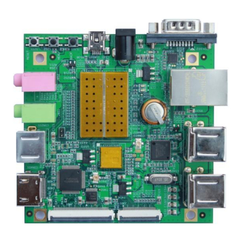
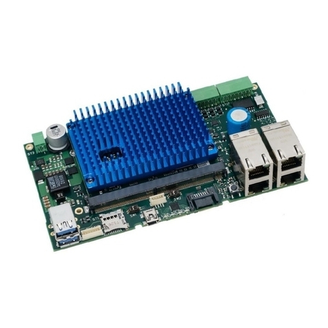
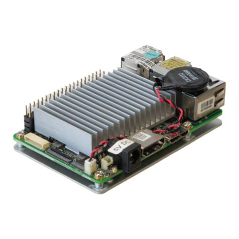
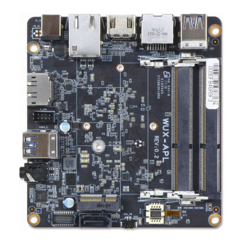
iWave iW-RainboW-G22M Installation manual

REL1.2
Page 1 of 62
RZ/G1E SODIMM SOM Hardware User Guide
iWave Systems Technologies Pvt. Ltd.
iW-RainboW-G22M
RZ/G1E SODIMM SOM
Hardware User Guide

REL1.2
Page 2 of 62
RZ/G1E SODIMM SOM Hardware User Guide
iWave Systems Technologies Pvt. Ltd.
Document Revision History
Document Number
iW-PREZZ-UM-01-R4.0-REL1.2-Hardware
Revision
Date
Description
1.0
27th Jan 2017
Official Release Version
1.1
3rd Oct 2017
•Section 2.8 is newly added.
•RZ/G1E pin mulitiplexing on SODIMM Edge is updated in Table 6.
•Orderble Part Number is updated in Table 11.
•Non substantive changes throughout the document.
1.2
14th Jan 2019
•Substantive changes throughout the document with respect to RZ/G1E R4.0
SOM
PROPRIETARY NOTICE: This document contains proprietary material for the sole use of the intended recipient(s). Do
not read this document if you are not the intended recipient. Any review, use, distribution or disclosure by others
is strictly prohibited. If you are not the intended recipient (or authorized to receive for the recipient), you are
hereby notified that any disclosure, copying distribution or use of any of the information contained within this
document is STRICTLY PROHIBITED. Thank you. “iWave Systems Tech. Pvt. Ltd.”

REL1.2
Page 3 of 62
RZ/G1E SODIMM SOM Hardware User Guide
iWave Systems Technologies Pvt. Ltd.
Disclaimer
iWave Systems reserves the right to change details in this publication including but not limited to any Product
specification without notice.
No warranty of accuracy is given concerning the contents of the information contained in this publication. To the
extent permitted by law no liability (including liability to any person by reason of negligence) will be accepted by
iWave Systems, its subsidiaries or employees for any direct or indirect loss or damage caused by omissions from or
inaccuracies in this document.
CPU and other major components used in this product may have several silicon errata associated with it. Under no
circumstances, iWave Systems shall be liable for the silicon errata and associated issues.
Trademarks
All registered trademarks, product names mentioned in this publication are the property of their respective owners
and used for identification purposes only.
Certification
iWave Systems Technologies Pvt. Ltd. is an ISO 9001:2015 Certified Company.
Warranty & RMA
Warranty support for Hardware: 1 Year from iWave or iWave's EMS partner.
For warranty terms, go through the below web link,
http://www.iwavesystems.com/support/warranty.html
For Return Merchandise Authorization (RMA), go through the below web link,
http://www.iwavesystems.com/support/rma.html
Technical Support
iWave Systems technical support team is committed to provide the best possible support for our customers so that
our Hardware and Software can be easily migrated and used.
For assistance, contact our Technical Support team at,
Email : support.ip@iwavesystems.com
Website : www.iwavesystems.com
Address : iWave Systems Technologies Pvt. Ltd.
# 7/B, 29th Main, BTM Layout 2nd Stage,
Bangalore, Karnataka,
India –560076

REL1.2
Page 4 of 62
RZ/G1E SODIMM SOM Hardware User Guide
iWave Systems Technologies Pvt. Ltd.
Table of Contents
1. INTRODUCTION ............................................................................................................................................7
1.1 Purpose .............................................................................................................................................................7
1.2 SODIMM SOM Overview...................................................................................................................................7
1.3 List of Acronyms................................................................................................................................................7
1.4 Terminlogy Description.....................................................................................................................................9
1.5 References ........................................................................................................................................................9
1.6 Important Note ...............................................................................................................................................10
2. ARCHITECTURE AND DESIGN....................................................................................................................... 11
2.1 RZ/G1E SODIMM SOM Block Diagram............................................................................................................11
2.2 RZ/G1E SODIMMSOM Features......................................................................................................................12
2.3 RZ/G1E CPU.....................................................................................................................................................14
2.4 Memory...........................................................................................................................................................15
2.4.1 DDR3 SDRAM ..............................................................................................................................................15
2.4.2 SPI NOR Flash ..............................................................................................................................................15
2.4.3 eMMC Flash ................................................................................................................................................16
2.4.4 Micro SD Slot (Optional)..............................................................................................................................16
2.5 WiFi and Bluetooth Interface..........................................................................................................................17
2.6 RTC Controller.................................................................................................................................................17
2.7 SODIMM PCB Edge Connector........................................................................................................................18
2.7.1 Gigabit Ethernet..........................................................................................................................................19
2.7.2 10/100 Ethernet (Optional).........................................................................................................................19
2.7.3 USB 2.0 OTG Interface.................................................................................................................................20
2.7.4 USB 2.0 Host Interface ................................................................................................................................20
2.7.5 SD Interface.................................................................................................................................................21
2.7.6 Parallel Camera Interface............................................................................................................................21
2.7.7 Parallel RGB Display Interface.....................................................................................................................22
2.7.8 I2S Audio Interface......................................................................................................................................22
2.7.9 CAN Interface ..............................................................................................................................................22
2.7.10 UART Interface ............................................................................................................................................23
2.7.11 SPI Interface ................................................................................................................................................23
2.7.12 I2C Interface................................................................................................................................................24
2.7.13 PWM Interface ............................................................................................................................................24
2.7.14 GPIO Interface.............................................................................................................................................24
2.7.15 JTAG Interface .............................................................................................................................................25
2.7.16 Power Input.................................................................................................................................................25
2.7.17 Reset Signal.................................................................................................................................................25
2.8 RZ/G1E PinMultiplexing on SODIMM .............................................................................................................38
2.9 RZ/G1E CPU Reference Schematic..................................................................................................................48
3. TECHNICAL SPECIFICATION.......................................................................................................................... 52
3.1 Electrical Characteristics .................................................................................................................................52
REL1.2
Page 5 of 62
RZ/G1E SODIMM SOM Hardware User Guide
iWave Systems Technologies Pvt. Ltd.
3.1.1 Power Input Requirement ...........................................................................................................................52
3.1.2 Power Input Sequencing..............................................................................................................................53
3.1.3 Power Consumption ....................................................................................................................................54
3.2 EnvironmentalCharacteristics.........................................................................................................................55
3.2.1 Environmental Specification........................................................................................................................55
3.2.2 Heat Sink .....................................................................................................................................................55
3.2.3 RoHS Compliance ........................................................................................................................................56
3.2.4 Electrostatic Discharge................................................................................................................................56
3.3 MechanicalCharacteristics..............................................................................................................................57
3.3.1 SODIMM SOM Mechanical Dimensions ......................................................................................................57
3.3.2 Guidelines to insert the SODIMM SOM into Carrier board .........................................................................58
3.3.3 SODIMM SOM removing procedure from Carrier board.............................................................................58
4. ORDERING INFORMATION .......................................................................................................................... 59
5. APPENDIX I................................................................................................................................................. 61
5.1 RZ/G1E SODIMM SOM Development Platform ..............................................................................................61

REL1.2
Page 6 of 62
RZ/G1E SODIMM SOM Hardware User Guide
iWave Systems Technologies Pvt. Ltd.
List of Figures
Figure 1: RZ/G1E SODIMM SOM Block Diagram.............................................................................................................11
Figure 2: RZ/G1E Simplified Block Diagram ....................................................................................................................14
Figure 3: SPI Flash Progarming Header...........................................................................................................................15
Figure 4: Wi-Fi/BT Module..............................................................................................................................................17
Figure 5: SODIMM PCB Edge Connector.........................................................................................................................18
Figure 6: SODIMM SOM Power Sequence......................................................................................................................53
Figure 7: Head Sink Dimensions......................................................................................................................................56
Figure 8: Mechanical dimension of SODIMM SOM ........................................................................................................57
Figure 9: Mechanical dimension of RZ/G1E SODIMM SOM- Side View..........................................................................57
Figure 10: SODIMM Module Insertion procedure ..........................................................................................................58
Figure 11: SODIMM Module Removing Procedure.........................................................................................................58
Figure 12: RZ/G1E SODIMM SOM Development Platform .............................................................................................61
List of Tables
Table 1: Acronyms & Abbreviations..................................................................................................................................7
Table 2: Terminology ........................................................................................................................................................9
Table 3: SPI Header.........................................................................................................................................................15
Table 4: Gigabit Ethernet Compatible Magnetics...........................................................................................................19
Table 5: 10/100Mbps Ethernet Compatible Magnetics..................................................................................................20
Table 6: 200-Pin PCB Edge Connector Pin Assignment...................................................................................................26
Table 7: RZ/G1E CPU IOMUX for SODIMM Edge Connector interfaces..........................................................................38
Table 8: Power Input Requirement.................................................................................................................................52
Table 9: Power Sequence Timing....................................................................................................................................53
Table 10: Power Consumption........................................................................................................................................54
Table 11: Environmental Specification ...........................................................................................................................55
Table 12: Orderable Product Part Numbers ...................................................................................................................59

REL1.2
Page 7 of 62
RZ/G1E SODIMM SOM Hardware User Guide
iWave Systems Technologies Pvt. Ltd.
1. INTRODUCTION
1.1 Purpose
This document is the Hardware User Guide for the RZ/G1E SODIMM System On Module based on the Renesas’s
RZ/G1E Application processor. This board is fully supported by iWave Systems Technologies Pvt. Ltd. This Guide
provides detailed information on the overall design and usage of the RZ/G1E SODIMM System On Module from a
Hardware Systems perspective.
1.2 SODIMM SOM Overview
The RZ/G1E SODIMM SOM is an extension of RZ/G1E CPU. Also, with the SOM approach one can reduce the cost and
time required for the development of customised solution on RZ/G1E platform. RZ/G1E SODIMM module has a form
factor of 67.6mm x 37mm and provides the functional requirements for an embedded application. A single
ruggedized SODIMM connector provides the carrier board interface to carry all the I/O signals to and from the
SODIMM module.
1.3 List of Acronyms
The following acronyms will be used throughout this document.
Table 1: Acronyms & Abbreviations
Acronyms
Abbreviations
ARM
Advanced RISC Machine
AVB
Audio Video Bridging
BPP
Bits Per Pixel
BSP
Board Support Package
CAN
Controller Area Network
CMOS
Complementary Metal-Oxide Semiconductor
CPU
Central Processing Unit
DDR3
Double Data RAM 3
DMA
Direct Memory Access
eMMC
Enhanced Multi Media Card
GB
Giga Byte
Gbps
Gigabits per sec
GPIO
General Purpose Input Output
HSCIF
High Speed Serial Communication Interface with FIFO
I2C
Inter-Integrated Circuit
IC
Integrated Circuit
JTAG
Joint Test Action Group
Kbps
Kilobits per second
LCD
Liquid Crystal Display

REL1.2
Page 8 of 62
RZ/G1E SODIMM SOM Hardware User Guide
iWave Systems Technologies Pvt. Ltd.
Acronyms
Abbreviations
MAC
Media Access Controller
MB
Mega Byte
Mbps
Megabits per sec
MHz
Mega Hertz
MMCIF
Multi-media card interface
MSIOF
Clock-Synchronized Serial Interface with FIFO
PCB
Printed Circuit Board
PWM
Pulse Width Modulation
QSPI
Quad Serial Peripheral Interface
RTC
Real Time Clock
SCIF
Serial Communication Interface with FIFO
SD
Secure Digital
SDHI
SD Card Host Interface
SSI
Serial Sound Interface
SODIMM
Small Outline Dual in-line Memory Module
SDRAM
Synchronous Dynamic Random Access Memory
SOM
System On Module
UART
Universal Asynchronous Receiver/Transmitter
USB
Universal Serial Bus
USB OTG
USB On The Go

REL1.2
Page 9 of 62
RZ/G1E SODIMM SOM Hardware User Guide
iWave Systems Technologies Pvt. Ltd.
1.4 Terminlogy Description
In this document, wherever Signal Type is mentioned, below terminology is used.
Table 2: Terminology
Terminology
Description
I
Input Signal
O
Output Signal
IO
Bidirectional Input/output Signal
CMOS
Complementary Metal Oxide Semiconductor Signal
DIFF
Differential Signal
OD
Open Drain Signal
OC
Open Collector Signal
Power
Power Pin
PU
Pull Up
PD
Pull Down
NA
Not Applicable
NC
Not Connected
Note: Signal Type does not include internal pull-ups or pull-downs implemented by the chip vendors and only includes
the pull-ups or pull-downs implemented On-SOM.
1.5 References
•RZ/G1E CPU Hardware User Manual
•200 Pin DDR S.O.DIMM Mechanical Specification

REL1.2
Page 10 of 62
RZ/G1E SODIMM SOM Hardware User Guide
iWave Systems Technologies Pvt. Ltd.
1.6 Important Note
RZ/G1E SODIMM Edge connector signal name mentioned in Table 6 is followed as per below format for easy
understanding.
•If CPU pin has multiplexing option and selected particular function, then the signal name is mentioned as
“Selected Function Name (GPIO Number)”
Example: CAN0_RX(GP6_14)
In this signal, CAN0_RX is the functionality which we are using and GP6_14 is the GPIO number.
•If CPU pin has multiplexing option and selected as GPIO function, then the signal name is mentioned as
“GPIO (GPIO Number)”
Example: GPIO(GP4_1)
In this signal, GPIO is MUX functionality which we are using and GP4_1 is the GPIO number.
•If CPU pin doesn’t have multiplexing option, then the signal name is mentioned as,
“Function name”
Example: USB0_DP
In this signal, functionality which we are using is USB0_DP
Note: The above naming is not applicable for other signals which are not connected to CPU.

REL1.2
Page 11 of 62
RZ/G1E SODIMM SOM Hardware User Guide
iWave Systems Technologies Pvt. Ltd.
2. ARCHITECTURE AND DESIGN
This section provides detailed information about the RZ/G1E SODIMM SOM features and Hardware architecture with
high level block diagram. Also, this section provides detailed information about SODIMM edge connector pin
assignment and usage.
2.1 RZ/G1E SODIMM SOM Block Diagram
CPU
RZ/G1E
DDR3 -512MB
(Upgradable)
SODIMM
PCB Edge
Connector
(200Pin)
DDR3 (32bit) DBSC
iW-RainboW-G22M - RZ/G1E SODIMM SOM Block Diagram
USB1 USB Host x 1
SD (4bit) x 1
SDHI0
USB OTG x 1
USB0
eMMC - 8GB
(Upgradable)
MMC MMC
Micro SD
Connector
(Optional)
SD (4bit) SDHI14
100/1000Mbps
Ethernet PHY
EtherAVB
100Mbps
Ethernet PHY
(Optional)
EtherMAC/
VI1
RMII x 1
GMII x 1
100/1000Mbps
Ethernet
100Mbps
Ethernet1
SPI Flash-16Mb
(Upgradable)
QSPI QSPI
DU0 RGB LCD (24bpp) x 1
SSI3/
SSI4
I2S x 1
CAN0,
CAN1
CAN x 2
HSCIF1,
HSCIF23
UART (with CTS & RTS) x 2
SCIF1,SCIF2,
SCIF3,SCIF5
UART x 4
SCIF4 Debug UART
I2C3,
I2C5
I2C x 2
MSIOF0
MSIOF1
MSIOF2
SPI x 32
TPU0,TPU2,
TPU3
PWM x 3
On-Board
Regulators
Power to
Peripherals
3.3V
GPIOs GPIOs
JTAG JTAG
RTC Controller
VRTC
VRTC
I2C3
Camera (8bit)1,2
¹ Since EtherMAC and VI1 are multiplexed in CPU, either one only can be used at a time. By default VI1 is supported.
2Since VI1 and MSIOF1 are shared the same SODIMM Edge pins, either one only can be used at a time. By default VI1 is supported.
3Since HSCIF2 interface is shared between Wi-Fi/BT and SODIMM Edge pins, either one only can be used at a time. By default Wi-Fi/BT module is supported.
4 Since SDHI1 interface is shared between Wi-Fi/BT module and µSD Connector, either one only can be used at a time. By default Wi-Fi/BT module is supported.
Voltage Level
Translator
JTAG
WiFi/BT
Module HSCIF23
Figure 1: RZ/G1E SODIMM SOM Block Diagram

REL1.2
Page 12 of 62
RZ/G1E SODIMM SOM Hardware User Guide
iWave Systems Technologies Pvt. Ltd.
2.2 RZ/G1E SODIMMSOM Features
The RZ/G1E SODIMM SOM supports the following features.
CPU
•Renesas’RZ/G1E Dual ARM Cortex®-A7 MPCore® @ 1GHz
Memory
•DDR3 SDRAM –512 MB (Expandable up to 2GB)
•SPI Flash - 16Mb (Expandable)
•eMMC Flash - 8GB (Expandable)
•Micro SD slot1(Optional)
Other On-SOM Features
•Gigabit Ethernet PHY Transceiver
•10/100Mbps Ethernet PHY Transceiver (Optional)
•Wi-Fi and Bluetooth Module1
•RTC controller
SODIMM PCB Edge Interfaces
•Gigabit Ethernet x 1 Port (through On-SOM Gigabit Ethernet PHY transceiver)
•10/100Mbps Ethernet x 1 Port (through On-SOM 100Mbps Ethernet PHY transceiver) (Optional)2
•USB 2.0 Host x 1 Port
•USB 2.0 OTG x 1 Port
•SD (4bit) x 1 Port
•Parallel Camera (VIN1 –8bit) x 1 Port2
•Parallel LCD (24bpp RGB) x 1 Port
•SSI/I2S (Audio Interface) x 1 Port
•CAN x 2 Ports
•Debug UART
•Data UART (with CTS & RTS) x 2 Ports3
•Data UART (without CTS & RTS) x 4 Ports4
•SPI x 3 Ports5
•I2C x 2 Ports
•PWM x 3 Ports
•GPIOs
•JTAG

REL1.2
Page 13 of 62
RZ/G1E SODIMM SOM Hardware User Guide
iWave Systems Technologies Pvt. Ltd.
•Power & Reset
General Specification
•Power Supply : 3.3V,3A
•Form Factor : 67.6mm x 37mm
¹ Since SDHI1 interface is shared between Wi-Fi/BT module and µSD Connector, either one only can be used at a time.
By default Wi-Fi/BT module is supported.
2 In RZ/G1E CPU, EtherMAC and VIN1 are multiplexed in same pins and so either one interface only can be used at a
time. By default, VIN1 camera interface is supported in RZ/G1E SODIMM SOM. iWave also supports separate RZ/G1E
SODIMM SOM with EtherMAC support instead of VIN1.
3 Since HSCIF2 interface TXD and RXD signals are shared between Wi-Fi/BT module and SODIMM Edge pins, either
one only can be used at a time. By default, Wi-Fi/BT module pins are supported.
4 Since SCIF5 interface is shared between Wi-Fi/BT module and SODIMM Edge pins, either one only can be used at a
time. By default, Edge pins are supported.
5 In RZ/G1E SODIMM SOM, VIN1 and MSIOF1 interface signals are connected to same pins of SODIMM Edge
connector (through isolating resistors) and so either one interface only can be used at a time. By default, VIN1
camera interface is supported on SODIMM Edge. In EtherMAC supported RZ/G1E SODIMM SOM, MSIOF1 (and some
extra GPIOs) is supported on SODIMM edge (instead of VIN1).

REL1.2
Page 14 of 62
RZ/G1E SODIMM SOM Hardware User Guide
iWave Systems Technologies Pvt. Ltd.
2.3 RZ/G1E CPU
The RZ/G1E SODIMM SOM is based on Renesas’s RZ/G1E CPU with built-in Dual ARM Cortex®-A7 MPCore® which can
operate up to 1 GHz/core. The Block Diagram of RZ/G1E CPU from Renesas’s website is shown below for reference.
Figure 2: RZ/G1E Simplified Block Diagram
Note: Please refer the latest RZ/G1E Datasheet & Reference Manual for more details which may be revised from time
to time.

REL1.2
Page 15 of 62
RZ/G1E SODIMM SOM Hardware User Guide
iWave Systems Technologies Pvt. Ltd.
2.4 Memory
2.4.1 DDR3 SDRAM
The RZ/G1E SODIMM SOM supports 512MB DDR3 RAM memory by default. This is connected to CPU in 32bit x 1ch
mode where it uses two 256MB DDR3-SDRAM ICs. This device operates at 1.5V voltage level. DDR3-SDRAM ICs are
physically located on top side of the SOM. The RAM size can be expandable up to maximum of 2GB. For customised
DDR3 memory based SOM contact iWave support team.
2.4.2 SPI NOR Flash
The RZ/G1E SODIMM SOM supports 16Mb SPI NOR Flash as default boot device. This is connected to QSPI controller
of the RZ/G1E CPU and operates at 3.3 Voltage level. While RZ/G1E booting, boot program in the on-chip ROM starts
up the QSPI and SYS-DMAC channel 1 and transfers the loader program previously stored in the SPI Flash to the on-
chip RAM via the QSPI controller. After loader program is transferred, the program automatically jumps to the top
address of the loader program. The SPI flash memory (U14) is physically located on bottom side of the SOM.
To program the boot code in to the SPI flash (for the first time or if boot code is corrupted), use iWave’s RZ/G1E SPI
Programmer Board through SPI Flash Programming Header (Example part: TMM-103-01-L-D). Optionally the external
SPI programmer can be used for programming the SPI flash through SPI Flash Programming Header (J2). Optionally
the JTAG Header, which is available on the RZ/G1E SODIMM carrier board can be used for programming the SPI
flash.
Figure 3: SPI Flash Progarming Header
Table 3: SPI Header
SI.No
Pin Number
Pin name
1
1
SPI_MISO
2
2
SPI_CS
3
3
SPI_MOSI
4
4
GND
5
5
VCC

REL1.2
Page 16 of 62
RZ/G1E SODIMM SOM Hardware User Guide
iWave Systems Technologies Pvt. Ltd.
6
6
SPI_SCK
2.4.3 eMMC Flash
The RZ/G1E SODIMM SOM supports 8GB eMMC Flash memory as mass storage. eMMC is directly connected to the
MMCIF controller of the RZ/G1E CPU in 8bit mode which supports MMC 4.41 and operating at 3.3V Voltage level.
The eMMC flash memory is physically located on bottom side of the SOM.
2.4.4 Micro SD Slot (Optional)
The RZ/G1E SODIMM SOM optionally supports Micro SD slot which can be used to connect Micro SD card as Mass
storage. Micro SD card connector (J1) is directly connected to the SDHI1 controller of the RZ/G1E CPU. It also
supports card detect feature through RZ/G1E GPIO “GP3_31”. The main power to Micro SD Card Connector is 3.3
Voltage.
The RZ/G1E SODIMM SOM optionally supports configurable IO voltage levels for SDHI1 lines which can be controlled
through CPU GPIO GP1_21. If GP1_21 is set to low, then 1.8V IO level is selected for SDHI1 lines. If GP1_21 is set to
high, then 3.3V IO level is selected for SDHI1 lines. Micro SD Connector is physically located on top side of the SOM.
Note: Since SDHI1 interface is shared between Wi-Fi/BT module and µSD Connector, either one only can be used at a
time. By default, WiFi and Bluetooth interface is supported. Please contact iwave if Micro SD support is required.

REL1.2
Page 17 of 62
RZ/G1E SODIMM SOM Hardware User Guide
iWave Systems Technologies Pvt. Ltd.
2.5 WiFi and Bluetooth Interface
The RZ/G1E SODIMM SOM supports WiFi and Bluetooth Interface through Microchip’s “ATWILC3000” module. The
ATWILC3000-MR110CA module is an IEEE 802.11 b/g/n RF/Baseband/Medium Access Control (MAC) link controller
and Bluetooth 4.0 compliant module. This module supports single stream 1x1 IEEE 802.11n mode providing up to 72
Mbps PHY rate. The ATWILC3000 module utilizes highly optimized IEEE 802.11 Bluetooth coexistence protocols, and
provides Secure Digital Input Output (SDIO) for interfacing with the host controller.
The RZ/G1E SODIMM SOM’s SDHI1 and HSCIF2 controllers are connected to WiFi and Bluetooth interface. It also
supports chip enable feature through RZ/G1E GPIO “GP3_31”and Interrupt feature through RZ/G1E GPIO “GP0_10”.
The main power to “ATWILC3000” module is 3.3 Voltage. Wi-Fi/BT module (U2) is physically located on top side of
the SOM as shown below.
Note: Since SDHI1 interface is shared between Wi-Fi/BT module and µSD Connector, either one only can be used at a
time. By default, Wi-Fi/BT module is supported.
Note: Since HSCIF2 interface TXD and RXD signals are shared between Wi-Fi/BT and SODIMM Edge pins, either one
only can be used at a time. By default, Wi-Fi/BT module pins are supported.
Note: Since SCIF5 interface is shared between Wi-Fi/BT module and SODIMM Edge pins, either one only can be used
at a time. By default, Edge pins are supported.
Figure 4: Wi-Fi/BT Module
2.6 RTC Controller
The RZ/G1E SODIMM SOM supports external RTC Controller “PCF85263AT/AJ” On-SOM for Real time clock support.
This external RTC Controller is connected to the RZ/G1E CPU through I2C3 Interface and operates at 3.3V voltage
level. In SOM power off condition, this device will take power from SODIMM Edge (VCC_RTC) coin cell power input
(Pin 183) and continues to keep the current time. The interrupt output from RTC controller is connected to RZ/G1E
GPIO “GP3_27”.

REL1.2
Page 18 of 62
RZ/G1E SODIMM SOM Hardware User Guide
iWave Systems Technologies Pvt. Ltd.
2.7 SODIMM PCB Edge Connector
The RZ/G1E SODIMM SOM Supports Mechnical specification of JEDEC Standard 200pin DDR S.O.DIMM PCB edge
connector. The interfaces which are available at SODIMM Edge connector are explained in the following sections.
Figure 5: SODIMM PCB Edge Connector
Number of Pins - 200
Connector Part - Not Applicable (On Board PCB Edge connector)
Mating Connector - 1473005-1 from TE Connectivity

REL1.2
Page 19 of 62
RZ/G1E SODIMM SOM Hardware User Guide
iWave Systems Technologies Pvt. Ltd.
2.7.1 Gigabit Ethernet
The RZ/G1E SODIMM SOM supports one 100/1000 Mbps Ethernet interface on SODIMM Edge connector. The MAC
is integrated in the RZ/G1E CPU and connected to the external Gigabit Ethernet PHY on SOM. Since MAC and PHY are
supported on SOM itself, only Magnetics are required on the carrier board. RZ/G1E SODIMM SOM also supports Link
and Activity indication LED control signals to SODIMM Edge.
The RZ/G1E SODIMM SOM supports “KSZ9031MNX” Ethernet PHY from Microchip. This PHY is interfaced with
RZ/G1E CPU EtherAVB and works at 3.3V IO voltage level. Since this PHY doesn’t recommend to connect any power
source to magnetic center tap pins, CTREF voltage to SODIMM Edge is not supported on SOM. It is recommended
that center tap pins of magnetics should be separated from one another and connected through separate 0.1uF
common mode capacitors to ground. The below table provides some of the compatible magnetics recommended by
the PHY Manufacturer.
Table 4: Gigabit Ethernet Compatible Magnetics
Part Description
Part Number
Manufacturer
Temperature
Gigabit Ethernet Discrete Transformer
TG1G-E001NZRL
HALO
-40°C to 85°C
Gigabit Ethernet Discrete Transformer
HX5008NL
Pulse
-40°C to 85°C
RJ45 Magjack with two Green LED
JK0654219NL
Pulse
0°C to 70°C
RJ45 Magjack with two Green LED
0826-1G1T-23-F
Bel Fuse
0°C to 70°C
For more details, refer SODIMM Edge connector pins 2, 4, 6, 8, 11, 12, 14, 15, 16 & 17 on Table 6.
Note: EtherAVB MAC of RZ/G1E CPU doesn’t support 10Mbps speed.
2.7.2 10/100 Ethernet (Optional)
The RZ/G1E SODIMM SOM optionally supports one 10/100 Mbps Ethernet interface on SODIMM Edge Connector.
The MAC is integrated in the RZ/G1E CPU and connected to the external 10/100 Ethernet PHY on SOM. Since MAC
and PHY are supported on SOM itself, only Magnetics are required on the carrier board. RZ/G1E SODIMM Edge
connector also supports Link and Activity indication LED control signals.
The RZ/G1E SODIMM SOM supports “KSZ8081RNBI” Ethernet PHY from Microchip. This PHY is interfaced with
RZ/G1E CPU EtherMAC and works at 3.3V IO voltage level. Since this PHY doesn’t recommend to connect any power
source to magnetic center tap pins. It is recommended that center tap pins of magnetics should be separated from
one another and connected through separate 0.1uF common mode capacitors to ground. The below table provides
some of the compatible magnetics recommended by the PHY Manufacturer.
For more details, refer SODIMM Edge connector pins 30, 33, 34, 35, 36 & 37 on Table 6.

REL1.2
Page 20 of 62
RZ/G1E SODIMM SOM Hardware User Guide
iWave Systems Technologies Pvt. Ltd.
Table 5: 10/100Mbps Ethernet Compatible Magnetics
Part Description
Part Number
Manufacturer
Temperature
RJ45 Magjack with Green, Orange –LED’s.
0821-1X1T-36-F
Bel Fuse
-40°C to 85°C
RJ45 Magjack with Green, Yellow –LED’s.
SI-46001-F
Bel Fuse
-40°C to 85°C
RJ45 Magjack with Green, Yellow –LED’s.
HFJ11-E2450E-L12RL
Halo Electronics
0°C to 70°C
RJ45 Magjack with Green, Yellow –LED’s.
JX0011D21BNL
Pulse Electronics
-40°C to 85°C
Note: In RZ/G1E CPU, EtherMAC and VIN1 are multiplexed in same pins and so either one interface only can be used
at a time. By default, VIN1 camera interface is supported in RZ/G1E SODIMM SOM. iWave also supports separate
RZ/G1E SODIMM SOM with EtherMAC support instead of VIN1.
2.7.3 USB 2.0 OTG Interface
The RZ/G1E SODIMM SOM supports one USB2.0 OTG interface on SODIMM Edge connector. RZ/G1E CPU’s USB0
OTG controller with integrated PHY is used for OTG interface which supports USB2.0 High-Speed (480 Mbps)/Full-
Speed (12 Mbps)/Low-Speed (1.5 Mbps) transfer. RZ/G1E CPU’s USB0 OTG controller OTG controller can operate in
Host or Function (Peripheral) mode.
The RZ/G1E CPU’s USB0 PHY output is directly connected to SODIMM Edge connector. Also, over current & USB ID
input from SODIMM Edge connector are connected to RZ/G1E CPU’s USB0_OVC(GP5_25) & GP4_6 pins
correspondingly. RZ/G1E CPU’s USB0_PWEN(GP5_24) is connected to SODIMM Edge connector for optionally
controlling USB1 VBUS power.
For more details, refer SODIMM Edge connector pins 76,77,78, 81 & 83 on Table 6.
2.7.4 USB 2.0 Host Interface
The RZ/G1E SODIMM SOM supports one USB2.0 Host interface on SODIMM Edge connector. RZ/G1E CPU’s USB1
Host controller with integrated PHY is used USB Host interface which supports USB2.0 High-Speed (480 Mbps)/Full-
Speed (12 Mbps)/Low-Speed (1.5 Mbps) transfer.
The RZ/G1E CPU’s USB1 PHY output is directly connected to SODIMM Edge connector. Also, over current input of
USB Port1 from SODIMM Edge connector are connected to RZ/G1E CPU’s USB1_OVC(GP5_27) pins for over current
detection. RZ/G1E CPU’s USB1_PWEN(GP5_26) is connected to SODIMM Edge connector for optionally controlling
USB1 VBUS power.
For more details, refer SODIMM Edge connector pins 39, 140, 188 & 190 on Table 6.
Table of contents
Other iWave Single Board Computer manuals

iWave
iWave iW-RainboW-G23S Installation manual

iWave
iWave iW-RainboW-G34S Installation manual

iWave
iWave iW-RainboW-G40S Installation manual

iWave
iWave Zynq Ultrascale+ MPSoC Installation manual

iWave
iWave iW-RainboW-G15M-SM Installation manual

iWave
iWave iW-RainboW-G34S Installation manual

iWave
iWave iW-RainboW-G36S User manual

iWave
iWave i.MX 8M Mini Installation manual

iWave
iWave iW-RainboW-G47M Installation manual

iWave
iWave iW-RainboW-G25M Installation manual