DecoBREEZE DBF0247 User manual

1
A Motor Assembly 1
B Light Bulb 1
C Wing Nut 1
DECORATIVE
TABLE TOP FAN
PACKAGE CONTENTS
PART DESCRIPTION QUANTITY
ASSEMBLY INSTRUCTIONS
X
9
Printed in China
ASSEMBLY INSTRUCTIONS
CARE AND MAINTENANCE
• Always unplug the appliance from the power supply before servicing.
• Clean parts with a duster, soft cloth or compressed air cannister (similar to computer cleaners).
Warning: Do not use cleaning solutions or abrasive material as it may damage the finish or
components of the fan.
USER SERVICING INSTRUCTIONS
This product employs overload protection (fuse). A blown fuse indicates an overload or short-circuit
situation. If the fuse blows, unplug the product from the outlet. Replace the fuse as per the user
servicing instructions (follow product marking for proper fuse rating) and check the product. If the
replacement fuse blows, a short-circuit may be present and the product should be discarded or
returned to an authorized service facility for examination and/or repair.
1. Grasp plug and remove from the receptacle or
other outlet device. Do not unplug by pulling on cord.
AA
Before beginning assembly of product, make sure all parts are present. Compare parts with
package contents list above. If any part is missing or damaged, do not attempt to assemble the
product. Contact customer service for replacement parts.
Estimated Assembly Time: 10-15 minutes
Tools Required for Assembly (not included): Phillips Screwdriver
PREPARATION
1. Loosen and remove Wing Nut (C) from bottom of
Fan/Light Base.
2. Carefully slide the Fan Head Unit (A) out of base and
mosaic glass center piece to expose the Lamp Socket (B).
3. Unscrew and remove light bulb (B) and replace.
4.
Carefully re-insert Fan Head Unit (A) back through the
mosaic glass center piece and into the Fan/Light Base.
5. Re-attach and firmly tighten Wing Nut (C) to compete
re-assembly process.
1
2
3
5
4
Questions, problems, missing parts? Before returning to your retailer, call our customer
service department at 1-800-979-4326, 8 a.m. - 5 p.m., PST, Monday - Friday.
ATTACH YOUR RECEIPT HERE
Serial Number Purchase Date
SAFETY INFORMATION
READ AND SAVE THESE. Please read and understand this entire manual before attempting to
assemble, operate or install the product. If you have any questions regarding the product, please
call customer service at 1-800-979-4326, 8 a.m. - 5 p.m., PST, Monday - Friday.
• Use the fan only for the specific purpose outlined in this instruction manual.
• Do not operate fan until fully assembled.
•Ensure the correct voltage is being used prior to plugging in your fan (120V AC Electrical Outlet).
• Unplug fan from outlet when not in use, when changing locations, before assembly or disassem-
bly, or prior to cleaning.
• Avoid contact with all moving parts. Never insert your fingers, pencils or other objects through the
fan grill during operation.
• Place the fan on a stable and level surface to avoid tipping or being knocked over accidentally.
• Do not operate the fan directly adjacent to curtains, plants, window coverings, etc. to avoid acci-
dental entanglement.
• While your fan is tolerant of exposure to most weather situations, it is recommended you bring the
fan unit into a covered or indoor location during periods of extreme cold, snow or rain.
• Do not submerge your fan under water and keep a safe distance from pools or outside water
features or irrigation sprinklers.
• Do not use an outdoor watering hose or pressure sprayer to clean your fan. Please see the
CARE AND MAINTENANCE section for specific instructions on cleaning.
• To avoid potential fire hazards, never place your fan or its electrical cord under rugs, or carpeting.
Do not cover cord with throw rugs, runners, or similar coverings. Do not route cord under furniture
or appliances. Arrange cord away from traffic area and where it will not be tripped over.
• Place the electrical cord away from busy areas to avoid accidental tripping and contact.
• Always insert or remove plug from the outlet by grabbing the plug by hand. Do not pull on the
electrical cord.
• Never operate the fan near an open flame or in the presence of explosive or combustible gases or
fumes.
• Should the fan (including the electrical cord) ever become damaged or a malfunction occurs,
discontinue operation at once until a certified repair has been made.
• Keep the fan out of the reach of children and pets.
• Do not expose infants or seniors to prolonged periods of direct cold air.
• Never attempt to disassemble or alter the product in any way not instructed by this manual.
• WARNING – To Reduce The Risk Of Fire Or Electric Shock, Do Not Use This Fan With Any
Solid-State Speed Control Device.
• Use only on GFCI protected receptacles.
ELECTRICAL SHOCK HAZARD.
Do not plug cord into outlet with wet hands. Follow manual for recommended usage.
DANGER
C
A
B
A
B
A
C
1
2. Open fuse cover. Using a flathead screwdriver tip,
slide open fuse access cover on top of attachment
plug towards the prongs.
3. Remove fuse carefully. Gently press on the end
of the fuse with the flat head screwdriver tip and
pull upward to remove. Risk of fire. Replace fuse only
with 5-amp, 125-volt fuse.
2
3
Screwdriver
(5A)
WARRANTY
Two (2) year limited warranty
1. This warranty applies only to the original owner of this product.
2. This warranty applies only to the repair or replacement of any manufactured parts of this fan unit.
The manufacturer reserves the right to determine if repair or replacement is warranted.
3. Operating the fan under conditions or usage not specified in the warnings, instructions, or care
directions in anyway may render this warranty void.
4. Unless otherwise prescribed by law, the manufacturer will not be liable for any personal injury, property
or any incidental or consequential damage of any kind (including water damage) resulting in misuse,
defects, malfunctions, improper installation or alterations of this product.
5. All parts of this product are guaranteed for a period of two (2) years from the date of purchase.
6. If you experience any problems or malfunctions with this fan, please contact our customer
service department at 1-800-979-4326, 8 a.m. - 5 p.m., PST, Monday - Friday.
7. This warranty gives you specific legal rights, and you may have other rights which vary from
state to state. The provisions of this warranty are in addition to, and not a modification of, or
subtraction from, the statutory warranties and other rights and remedies contained in any applicable
legislation. To the extent that any provisions of this warranty are consistent with any applicable law,
such provision shall be deemed voided or amended, as necessary, to comply with such law.
4. Close fuse cover. Slide closed the fuse access
cover on top of the plug and plug back into the outlet. 4
(5A)
Confirm that the fan switch is not in the OFF position.
Confirm the plug connectors are perfectly joined.
The fan will not oscillate. Push down on knob on top of motor housing to activate oscillation.
TROUBLESHOOTING
PROBLEM CORRECTIVE ACTION
The fan will not operate.
If you have any questions regarding the product, please call customer service at 1-800-979-4326,
8 a.m. - 5 p.m., PST, Monday - Friday. Do not attempt to repair or modify any mechanical or electrical
parts of this fan. Doing so may void the warranty.
OPERATION INSTRUCTIONS
• The speed control knob (H) is located on the top rear
of fan motor assembly (J). Position 0 = off,
position I = low speed, position II = medium speed
and position III = high speed. Simply twist switch to
desired position to operate.
• The fan can operate in stationary or oscillation mode.
The oscillation knob (I) is located on the top rear of
fan motor assembly (J). To engage the oscillation function,
simply depress the button. To stop, pull up.
• The fan features a telescoping upper pole (X). To set
at the desired height, simply loosen and then tighten the
Height adustment knob (W).
• The fan head can also tilt slightly for added adjustment.
Loosen tilt adjustment knob (K) and pitch the fan head to
the desired angle and then retighten.
H
I
J
A
B
C
Page 1
Page 2 Page 3
Page 4 Page 5
Page 6 Page 7 Page 8 Page 9
Page 10 Page 11
Page 12
NOTE: Start Canadian French section here,
followed by Latin American Spanish.
All covers will have page number.
100%
BLACK
FONT & SOFTWARE USAGE STATEMENT
COLOR USAGE & PRINT REQUIREMENTS
ALL INSTRUCTION MANUALS AND RELATED MATERIAL CREATED THROUGH
ADAPTATION OF THESE TEMPLATES MUST BE APPROVED BY LOWE’S
BRAND PACKAGING DEPARTMENT PRIOR TO PRODUCTION.
CONTACT: BRAND PACKAGING DEPARTMENT, LOWE’S COMPANIES, INC.
ATTN: PACKAGING STANDARDS
1000 LOWE’S BOULEVARD, MAIL STOP: 4WTD
MOORESVILLE, NC 28117
704-758-2785
DO NOT USE ANY COLOR GRAPHICS OR PHOTOGRAPHY IN YOUR INSTRUCTION
MANUALS. INSTRUCTION MANUALS PRINT IN GREYSCALE ONLY.
ALL GRAPHICS SHOWN ARE FOR SIZE AND POSITION ONLY; FINAL LINE-ART GRAPHICS
ARE REQUIRED FOR RELEASE TO PRESS.
IMPORTANT VENDOR NOTE
VENDORS ARE RESPONSIBLE FOR THE EXECUTION AND ACCURACY OF THEIR
INSTRUCTION MANUALS. THEY ARE SOLELY RESPONSIBLE FOR INSERTING ALL OF THE
CORRECT LEGAL CERTIFICATION, WARNING, WARRANTY, AND OTHER APPLICABLE
PRODUCT INFORMATION. HARDWARE MUST BE SHOWN AS ACTUAL SIZE IN THE
HARDWARE CONTENTS SECTION WITH LINE ART DRAWING OF THE HARDWARE, THE
DIMENSIONS, NAME DESCRIPTOR AND QUANTITY. LOWE’S IS NOT RESPONSIBLE FOR
ANY INCURRED DESIGN, TRANSLATION OR PRINTING COSTS. PLEASE REFER TO THE
TRANSLATION REQUIREMENTS ON LOWESLINK.COM
• FONTS USED ON THIS FILE: SEE FONT LEGEND.
• CONTACT YOUR APPROPRIATE FONT VENDOR TO PURCHASE THE REQUIRED FONTS
FOR THIS PACKAGE LINE.
• ADOBE ILLUSTRATOR CS3 WAS USED TO CREATE THIS FILE.
LOWE’S REQUIRES EACH VENDOR TO OBTAIN THEIR OWN LINE-ART GRAPHICS. ALL INSTRUCTION MANUAL GRAPHICS WILL
BE APPROVED BY LOWE’S BRAND MANAGEMENT DURING PROOFING.
THIS DESIGN IS PROPRIETARY AND CONFIDENTIAL TO LOWE’S COMPANIES, INC. AND CANNOT BE COPIED OR OTHERWISE
REPRODUCED OR USED WITHOUT THE EXPRESS WRITTEN PERMISSION OF LOWE’S.
THESE ARE THE PANTONE COLORS THAT ARE USED IN THIS FILE.
THESE MUST BE USED WHEN CREATING ANY OTHER PACKAGING.
THE ADDITION OF OTHER SPOT COLORS IS NOT PERMITTED.
ARTWORK DISCLAIMERS
FONT LEGEND
ALL FONTS MUST BE ARIAL BOLD OR ARIAL REGULAR, 12 PT. (MINIMUM) ON 14 PT. LEADING UNLESS OTHERWISE SPECIFIED.
REQUIRED PAPER TYPE
USE THE FOLLOWING PAPER FOR YOUR INSTRUCTION MANUALS:
• PAPER BASIS WEIGHT: 20-lb. PAPER OR 75 GRAMS/SQ METER
• DOCUMENT SIZE: PRINTED TWO-SIDES ON TABLOID OR A3 AND FOLDS
TO LETTER SIZE OR A4. INCLUDE SAMPLE MOCK-UP TO INDICATE
FOLD(S) AND PAGE LAYOUT.
THIS COLOR IS USED FOR
NOTES AND DOES NOT
PRINT.
CALL OUTS
(DO NOT PRINT)
THIS COLOR INDICATES
ALL TEXT TO BE CHANGED
WITH PRODUCT SPECIFIC
TEXT.
EDITABLE TEXT
(DO NOT PRINT)

2
A Motor Assembly 1
B Light Bulb 1
C Wing Nut 1
DECORATIVE
TABLE TOP FAN
PACKAGE CONTENTS
PART DESCRIPTION QUANTITY
ASSEMBLY INSTRUCTIONS
X
9
Printed in China
ASSEMBLY INSTRUCTIONS
CARE AND MAINTENANCE
• Always unplug the appliance from the power supply before servicing.
• Clean parts with a duster, soft cloth or compressed air cannister (similar to computer cleaners).
Warning: Do not use cleaning solutions or abrasive material as it may damage the finish or
components of the fan.
USER SERVICING INSTRUCTIONS
This product employs overload protection (fuse). A blown fuse indicates an overload or short-circuit
situation. If the fuse blows, unplug the product from the outlet. Replace the fuse as per the user
servicing instructions (follow product marking for proper fuse rating) and check the product. If the
replacement fuse blows, a short-circuit may be present and the product should be discarded or
returned to an authorized service facility for examination and/or repair.
1. Grasp plug and remove from the receptacle or
other outlet device. Do not unplug by pulling on cord.
AA
Before beginning assembly of product, make sure all parts are present. Compare parts with
package contents list above. If any part is missing or damaged, do not attempt to assemble the
product. Contact customer service for replacement parts.
Estimated Assembly Time: 10-15 minutes
Tools Required for Assembly (not included): Phillips Screwdriver
PREPARATION
1. Loosen and remove Wing Nut (C) from bottom of
Fan/Light Base.
2. Carefully slide the Fan Head Unit (A) out of base and
mosaic glass center piece to expose the Lamp Socket (B).
3. Unscrew and remove light bulb (B) and replace.
4.
Carefully re-insert Fan Head Unit (A) back through the
mosaic glass center piece and into the Fan/Light Base.
5. Re-attach and firmly tighten Wing Nut (C) to compete
re-assembly process.
1
2
3
5
4
Questions, problems, missing parts? Before returning to your retailer, call our customer
service department at 1-800-979-4326, 8 a.m. - 5 p.m., PST, Monday - Friday.
ATTACH YOUR RECEIPT HERE
Serial Number Purchase Date
SAFETY INFORMATION
READ AND SAVE THESE. Please read and understand this entire manual before attempting to
assemble, operate or install the product. If you have any questions regarding the product, please
call customer service at 1-800-979-4326, 8 a.m. - 5 p.m., PST, Monday - Friday.
• Use the fan only for the specific purpose outlined in this instruction manual.
• Do not operate fan until fully assembled.
•Ensure the correct voltage is being used prior to plugging in your fan (120V AC Electrical Outlet).
• Unplug fan from outlet when not in use, when changing locations, before assembly or disassem-
bly, or prior to cleaning.
• Avoid contact with all moving parts. Never insert your fingers, pencils or other objects through the
fan grill during operation.
• Place the fan on a stable and level surface to avoid tipping or being knocked over accidentally.
• Do not operate the fan directly adjacent to curtains, plants, window coverings, etc. to avoid acci-
dental entanglement.
• While your fan is tolerant of exposure to most weather situations, it is recommended you bring the
fan unit into a covered or indoor location during periods of extreme cold, snow or rain.
• Do not submerge your fan under water and keep a safe distance from pools or outside water
features or irrigation sprinklers.
• Do not use an outdoor watering hose or pressure sprayer to clean your fan. Please see the
CARE AND MAINTENANCE section for specific instructions on cleaning.
• To avoid potential fire hazards, never place your fan or its electrical cord under rugs, or carpeting.
Do not cover cord with throw rugs, runners, or similar coverings. Do not route cord under furniture
or appliances. Arrange cord away from traffic area and where it will not be tripped over.
• Place the electrical cord away from busy areas to avoid accidental tripping and contact.
• Always insert or remove plug from the outlet by grabbing the plug by hand. Do not pull on the
electrical cord.
• Never operate the fan near an open flame or in the presence of explosive or combustible gases or
fumes.
• Should the fan (including the electrical cord) ever become damaged or a malfunction occurs,
discontinue operation at once until a certified repair has been made.
• Keep the fan out of the reach of children and pets.
• Do not expose infants or seniors to prolonged periods of direct cold air.
• Never attempt to disassemble or alter the product in any way not instructed by this manual.
• WARNING – To Reduce The Risk Of Fire Or Electric Shock, Do Not Use This Fan With Any
Solid-State Speed Control Device.
• Use only on GFCI protected receptacles.
ELECTRICAL SHOCK HAZARD.
Do not plug cord into outlet with wet hands. Follow manual for recommended usage.
DANGER
C
A
B
A
B
A
C
1
2. Open fuse cover. Using a flathead screwdriver tip,
slide open fuse access cover on top of attachment
plug towards the prongs.
3. Remove fuse carefully. Gently press on the end
of the fuse with the flat head screwdriver tip and
pull upward to remove. Risk of fire. Replace fuse only
with 5-amp, 125-volt fuse.
2
3
Screwdriver
(5A)
WARRANTY
Two (2) year limited warranty
1. This warranty applies only to the original owner of this product.
2. This warranty applies only to the repair or replacement of any manufactured parts of this fan unit.
The manufacturer reserves the right to determine if repair or replacement is warranted.
3. Operating the fan under conditions or usage not specified in the warnings, instructions, or care
directions in anyway may render this warranty void.
4. Unless otherwise prescribed by law, the manufacturer will not be liable for any personal injury, property
or any incidental or consequential damage of any kind (including water damage) resulting in misuse,
defects, malfunctions, improper installation or alterations of this product.
5. All parts of this product are guaranteed for a period of two (2) years from the date of purchase.
6. If you experience any problems or malfunctions with this fan, please contact our customer
service department at 1-800-979-4326, 8 a.m. - 5 p.m., PST, Monday - Friday.
7. This warranty gives you specific legal rights, and you may have other rights which vary from
state to state. The provisions of this warranty are in addition to, and not a modification of, or
subtraction from, the statutory warranties and other rights and remedies contained in any applicable
legislation. To the extent that any provisions of this warranty are consistent with any applicable law,
such provision shall be deemed voided or amended, as necessary, to comply with such law.
4. Close fuse cover. Slide closed the fuse access
cover on top of the plug and plug back into the outlet.
4
(5A)
Confirm that the fan switch is not in the OFF position.
Confirm the plug connectors are perfectly joined.
The fan will not oscillate. Push down on knob on top of motor housing to activate oscillation.
TROUBLESHOOTING
PROBLEM CORRECTIVE ACTION
The fan will not operate.
If you have any questions regarding the product, please call customer service at 1-800-979-4326,
8 a.m. - 5 p.m., PST, Monday - Friday. Do not attempt to repair or modify any mechanical or electrical
parts of this fan. Doing so may void the warranty.
OPERATION INSTRUCTIONS
• The speed control knob (H) is located on the top rear
of fan motor assembly (J). Position 0 = off,
position I = low speed, position II = medium speed
and position III = high speed. Simply twist switch to
desired position to operate.
• The fan can operate in stationary or oscillation mode.
The oscillation knob (I) is located on the top rear of
fan motor assembly (J). To engage the oscillation function,
simply depress the button. To stop, pull up.
• The fan features a telescoping upper pole (X). To set
at the desired height, simply loosen and then tighten the
Height adustment knob (W).
• The fan head can also tilt slightly for added adjustment.
Loosen tilt adjustment knob (K) and pitch the fan head to
the desired angle and then retighten.
H
I
J
A
B
C
Page 1
Page 2 Page 3
Page 4 Page 5
Page 6 Page 7 Page 8 Page 9
Page 10 Page 11
Page 12
NOTE: Start Canadian French section here,
followed by Latin American Spanish.
All covers will have page number.
100%
BLACK
FONT & SOFTWARE USAGE STATEMENT
COLOR USAGE & PRINT REQUIREMENTS
ALL INSTRUCTION MANUALS AND RELATED MATERIAL CREATED THROUGH
ADAPTATION OF THESE TEMPLATES MUST BE APPROVED BY LOWE’S
BRAND PACKAGING DEPARTMENT PRIOR TO PRODUCTION.
CONTACT: BRAND PACKAGING DEPARTMENT, LOWE’S COMPANIES, INC.
ATTN: PACKAGING STANDARDS
1000 LOWE’S BOULEVARD, MAIL STOP: 4WTD
MOORESVILLE, NC 28117
704-758-2785
DO NOT USE ANY COLOR GRAPHICS OR PHOTOGRAPHY IN YOUR INSTRUCTION
MANUALS. INSTRUCTION MANUALS PRINT IN GREYSCALE ONLY.
ALL GRAPHICS SHOWN ARE FOR SIZE AND POSITION ONLY; FINAL LINE-ART GRAPHICS
ARE REQUIRED FOR RELEASE TO PRESS.
IMPORTANT VENDOR NOTE
VENDORS ARE RESPONSIBLE FOR THE EXECUTION AND ACCURACY OF THEIR
INSTRUCTION MANUALS. THEY ARE SOLELY RESPONSIBLE FOR INSERTING ALL OF THE
CORRECT LEGAL CERTIFICATION, WARNING, WARRANTY, AND OTHER APPLICABLE
PRODUCT INFORMATION. HARDWARE MUST BE SHOWN AS ACTUAL SIZE IN THE
HARDWARE CONTENTS SECTION WITH LINE ART DRAWING OF THE HARDWARE, THE
DIMENSIONS, NAME DESCRIPTOR AND QUANTITY. LOWE’S IS NOT RESPONSIBLE FOR
ANY INCURRED DESIGN, TRANSLATION OR PRINTING COSTS. PLEASE REFER TO THE
TRANSLATION REQUIREMENTS ON LOWESLINK.COM
• FONTS USED ON THIS FILE: SEE FONT LEGEND.
• CONTACT YOUR APPROPRIATE FONT VENDOR TO PURCHASE THE REQUIRED FONTS
FOR THIS PACKAGE LINE.
• ADOBE ILLUSTRATOR CS3 WAS USED TO CREATE THIS FILE.
LOWE’S REQUIRES EACH VENDOR TO OBTAIN THEIR OWN LINE-ART GRAPHICS. ALL INSTRUCTION MANUAL GRAPHICS WILL
BE APPROVED BY LOWE’S BRAND MANAGEMENT DURING PROOFING.
THIS DESIGN IS PROPRIETARY AND CONFIDENTIAL TO LOWE’S COMPANIES, INC. AND CANNOT BE COPIED OR OTHERWISE
REPRODUCED OR USED WITHOUT THE EXPRESS WRITTEN PERMISSION OF LOWE’S.
THESE ARE THE PANTONE COLORS THAT ARE USED IN THIS FILE.
THESE MUST BE USED WHEN CREATING ANY OTHER PACKAGING.
THE ADDITION OF OTHER SPOT COLORS IS NOT PERMITTED.
ARTWORK DISCLAIMERS
FONT LEGEND
ALL FONTS MUST BE ARIAL BOLD OR ARIAL REGULAR, 12 PT. (MINIMUM) ON 14 PT. LEADING UNLESS OTHERWISE SPECIFIED.
REQUIRED PAPER TYPE
USE THE FOLLOWING PAPER FOR YOUR INSTRUCTION MANUALS:
• PAPER BASIS WEIGHT: 20-lb. PAPER OR 75 GRAMS/SQ METER
• DOCUMENT SIZE: PRINTED TWO-SIDES ON TABLOID OR A3 AND FOLDS
TO LETTER SIZE OR A4. INCLUDE SAMPLE MOCK-UP TO INDICATE
FOLD(S) AND PAGE LAYOUT.
THIS COLOR IS USED FOR
NOTES AND DOES NOT
PRINT.
CALL OUTS
(DO NOT PRINT)
THIS COLOR INDICATES
ALL TEXT TO BE CHANGED
WITH PRODUCT SPECIFIC
TEXT.
EDITABLE TEXT
(DO NOT PRINT)

3
FAN HEAD
ASSEMBLY
INSTRUCTIONS
PACKAGE CONTENTS
FAN HEAD ASSEMBLY INSTRUCTIONS
X
9
Printed in China
FAN HEAD ASSEMBLY INSTRUCTIONS
CARE AND MAINTENANCE
• Always unplug the appliance from the power supply before servicing.
• Clean parts with a duster, soft cloth or compressed air cannister (similar to computer cleaners).
Warning: Do not use cleaning solutions or abrasive material as it may damage the finish or
components of the fan.
USER SERVICING INSTRUCTIONS
This product employs overload protection (fuse). A blown fuse indicates an overload or short-circuit
situation. If the fuse blows, unplug the product from the outlet. Replace the fuse as per the user
servicing instructions (follow product marking for proper fuse rating) and check the product. If the
replacement fuse blows, a short-circuit may be present and the product should be discarded or
returned to an authorized service facility for examination and/or repair.
1. Grasp plug and remove from the receptacle or
other outlet device. Do not unplug by pulling on cord.
1. Remove Black Grill Locker (C) from Motor
Assembly (E).
2. Slide on Back Grill (D) on to front of Motor
Assembly (E) with the handle at the top center.
3. Attach Black Grill Locker (C) and rotate clockwise
to tighten.
4.
Remove 5x8 Screw (G) from the Fan Blade (B) hozel
piece. Slide Fan Blade (B) on to Motor Shaft (H) and
re-insert 5x8 Screw (G) and tighten firmly.
5. Open all grill clasps on Front Grill (A). Remove Safety
Screw (I) from bottom of Front Grill (A) and place aside
momentarily. Position Grill Clip (F) at the top center of
Back Grill (D) and hook over frame to secure. Secure all
grill clasps so both grill frames are pressed together inside
each clasp. Re-attach Safety Screw (I) and secure.
1
2
3
5
4
Questions, problems, missing parts? Before returning to your retailer, call our customer
service department at 1-800-979-4326, 8 a.m. - 5 p.m., PST, Monday - Friday.
ATTACH YOUR RECEIPT HERE
Serial Number Purchase Date
6. The fan head is now ready for attaching to the
fan base.
6
1
2. Open fuse cover. Using a flathead screwdriver tip,
slide open fuse access cover on top of attachment
plug towards the prongs.
3. Remove fuse carefully. Gently press on the end
of the fuse with the flat head screwdriver tip and
pull upward to remove. Risk of fire. Replace fuse only
with 5-amp, 125-volt fuse.
2
3
Screwdriver
(5A)
WARRANTY
Two (2) year limited warranty
1. This warranty applies only to the original owner of this product.
2. This warranty applies only to the repair or replacement of any manufactured parts of this fan unit.
The manufacturer reserves the right to determine if repair or replacement is warranted.
3. Operating the fan under conditions or usage not specified in the warnings, instructions, or care
directions in anyway may render this warranty void.
4. Unless otherwise prescribed by law, the manufacturer will not be liable for any personal injury, property
or any incidental or consequential damage of any kind (including water damage) resulting in misuse,
defects, malfunctions, improper installation or alterations of this product.
5. All parts of this product are guaranteed for a period of two (2) years from the date of purchase.
6. If you experience any problems or malfunctions with this fan, please contact our customer
service department at 1-800-979-4326, 8 a.m. - 5 p.m., PST, Monday - Friday.
7. This warranty gives you specific legal rights, and you may have other rights which vary from
state to state. The provisions of this warranty are in addition to, and not a modification of, or
subtraction from, the statutory warranties and other rights and remedies contained in any applicable
legislation. To the extent that any provisions of this warranty are consistent with any applicable law,
such provision shall be deemed voided or amended, as necessary, to comply with such law.
4. Close fuse cover. Slide closed the fuse access
cover on top of the plug and plug back into the outlet.
4
(5A)
Confirm that the fan switch is not in the OFF position.
Confirm the plug connectors are perfectly joined.
The fan will not oscillate. Push down on knob on top of motor housing to activate oscillation.
TROUBLESHOOTING
PROBLEM CORRECTIVE ACTION
The fan will not operate.
If you have any questions regarding the product, please call customer service at 1-800-979-4326,
8 a.m. - 5 p.m., PST, Monday - Friday. Do not attempt to repair or modify any mechanical or electrical
parts of this fan. Doing so may void the warranty.
OPERATION INSTRUCTIONS
• The speed control knob (H) is located on the top rear
of fan motor assembly (J). Position 0 = off,
position I = low speed, position II = medium speed
and position III = high speed. Simply twist switch to
desired position to operate.
• The fan can operate in stationary or oscillation mode.
The oscillation knob (I) is located on the top rear of
fan motor assembly (J). To engage the oscillation function,
simply depress the button. To stop, pull up.
• The fan features a telescoping upper pole (X). To set
at the desired height, simply loosen and then tighten the
Height adustment knob (W).
• The fan head can also tilt slightly for added adjustment.
Loosen tilt adjustment knob (K) and pitch the fan head to
the desired angle and then retighten.
H
I
J
D
E
E
C
C
B
GH
AFD
IJ
A Front fan grill 1
B Fan blade 1
C Back grill locker 1
D Back grill 1
E Motor assembly 1
F Grill clip 1
G M5x8 screw 1
H Motor shaft 1
I M2.5x8 screw 1
J M2.5 nut 1
K Speed control knob 1
L Oscillation knob 1
PART DESCRIPTION QUANTITY
AF
BG
C
DHEK
L
J
I
AA
Before beginning assembly of product, make sure all parts are present. Compare parts with
package contents list above. If any part is missing or damaged, do not attempt to assemble the
product. Contact customer service for replacement parts.
Estimated Assembly Time: 10-15 minutes
Tools Required for Assembly (not included): Phillips Screwdriver
PREPARATION
SAFETY INFORMATION
READ AND SAVE THESE. Please read and understand this entire manual before attempting to
assemble, operate or install the product. If you have any questions regarding the product, please
call customer service at 1-800-979-4326, 8 a.m. - 5 p.m., PST, Monday - Friday.
• Use the fan only for the specific purpose outlined in this instruction manual.
• Do not operate fan until fully assembled.
•Ensure the correct voltage is being used prior to plugging in your fan (120V AC Electrical Outlet).
• Unplug fan from outlet when not in use, when changing locations, before assembly or disassem-
bly, or prior to cleaning.
• Avoid contact with all moving parts. Never insert your fingers, pencils or other objects through the
fan grill during operation.
• Place the fan on a stable and level surface to avoid tipping or being knocked over accidentally.
• Do not operate the fan directly adjacent to curtains, plants, window coverings, etc. to avoid acci-
dental entanglement.
• While your fan is tolerant of exposure to most weather situations, it is recommended you bring the
fan unit into a covered or indoor location during periods of extreme cold, snow or rain.
• Do not submerge your fan under water and keep a safe distance from pools or outside water
features or irrigation sprinklers.
• Do not use an outdoor watering hose or pressure sprayer to clean your fan. Please see the
CARE AND MAINTENANCE section for specific instructions on cleaning.
• To avoid potential fire hazards, never place your fan or its electrical cord under rugs, or carpeting.
Do not cover cord with throw rugs, runners, or similar coverings. Do not route cord under furniture
or appliances. Arrange cord away from traffic area and where it will not be tripped over.
• Place the electrical cord away from busy areas to avoid accidental tripping and contact.
• Always insert or remove plug from the outlet by grabbing the plug by hand. Do not pull on the
electrical cord.
• Never operate the fan near an open flame or in the presence of explosive or combustible gases or
fumes.
• Should the fan (including the electrical cord) ever become damaged or a malfunction occurs,
discontinue operation at once until a certified repair has been made.
• Keep the fan out of the reach of children and pets.
• Do not expose infants or seniors to prolonged periods of direct cold air.
• Never attempt to disassemble or alter the product in any way not instructed by this manual.
• WARNING – To Reduce The Risk Of Fire Or Electric Shock, Do Not Use This Fan With Any
Solid-State Speed Control Device.
• Use only on GFCI protected receptacles.
ELECTRICAL SHOCK HAZARD.
Do not plug cord into outlet with wet hands. Follow manual for recommended usage.
DANGER
Page 1
Page 2 Page 3
Page 4 Page 5
Page 6 Page 7 Page 8 Page 9
Page 10 Page 11
Page 12
NOTE: Start Canadian French section here,
followed by Latin American Spanish.
All covers will have page number.
100%
BLACK
FONT & SOFTWARE USAGE STATEMENT
COLOR USAGE & PRINT REQUIREMENTS
ALL INSTRUCTION MANUALS AND RELATED MATERIAL CREATED THROUGH
ADAPTATION OF THESE TEMPLATES MUST BE APPROVED BY LOWE’S
BRAND PACKAGING DEPARTMENT PRIOR TO PRODUCTION.
CONTACT: BRAND PACKAGING DEPARTMENT, LOWE’S COMPANIES, INC.
ATTN: PACKAGING STANDARDS
1000 LOWE’S BOULEVARD, MAIL STOP: 4WTD
MOORESVILLE, NC 28117
704-758-2785
DO NOT USE ANY COLOR GRAPHICS OR PHOTOGRAPHY IN YOUR INSTRUCTION
MANUALS. INSTRUCTION MANUALS PRINT IN GREYSCALE ONLY.
ALL GRAPHICS SHOWN ARE FOR SIZE AND POSITION ONLY; FINAL LINE-ART GRAPHICS
ARE REQUIRED FOR RELEASE TO PRESS.
IMPORTANT VENDOR NOTE
VENDORS ARE RESPONSIBLE FOR THE EXECUTION AND ACCURACY OF THEIR
INSTRUCTION MANUALS. THEY ARE SOLELY RESPONSIBLE FOR INSERTING ALL OF THE
CORRECT LEGAL CERTIFICATION, WARNING, WARRANTY, AND OTHER APPLICABLE
PRODUCT INFORMATION. HARDWARE MUST BE SHOWN AS ACTUAL SIZE IN THE
HARDWARE CONTENTS SECTION WITH LINE ART DRAWING OF THE HARDWARE, THE
DIMENSIONS, NAME DESCRIPTOR AND QUANTITY. LOWE’S IS NOT RESPONSIBLE FOR
ANY INCURRED DESIGN, TRANSLATION OR PRINTING COSTS. PLEASE REFER TO THE
TRANSLATION REQUIREMENTS ON LOWESLINK.COM
• FONTS USED ON THIS FILE: SEE FONT LEGEND.
• CONTACT YOUR APPROPRIATE FONT VENDOR TO PURCHASE THE REQUIRED FONTS
FOR THIS PACKAGE LINE.
• ADOBE ILLUSTRATOR CS3 WAS USED TO CREATE THIS FILE.
LOWE’S REQUIRES EACH VENDOR TO OBTAIN THEIR OWN LINE-ART GRAPHICS. ALL INSTRUCTION MANUAL GRAPHICS WILL
BE APPROVED BY LOWE’S BRAND MANAGEMENT DURING PROOFING.
THIS DESIGN IS PROPRIETARY AND CONFIDENTIAL TO LOWE’S COMPANIES, INC. AND CANNOT BE COPIED OR OTHERWISE
REPRODUCED OR USED WITHOUT THE EXPRESS WRITTEN PERMISSION OF LOWE’S.
THESE ARE THE PANTONE COLORS THAT ARE USED IN THIS FILE.
THESE MUST BE USED WHEN CREATING ANY OTHER PACKAGING.
THE ADDITION OF OTHER SPOT COLORS IS NOT PERMITTED.
ARTWORK DISCLAIMERS
FONT LEGEND
ALL FONTS MUST BE ARIAL BOLD OR ARIAL REGULAR, 12 PT. (MINIMUM) ON 14 PT. LEADING UNLESS OTHERWISE SPECIFIED.
REQUIRED PAPER TYPE
USE THE FOLLOWING PAPER FOR YOUR INSTRUCTION MANUALS:
• PAPER BASIS WEIGHT: 20-lb. PAPER OR 75 GRAMS/SQ METER
• DOCUMENT SIZE: PRINTED TWO-SIDES ON TABLOID OR A3 AND FOLDS
TO LETTER SIZE OR A4. INCLUDE SAMPLE MOCK-UP TO INDICATE
FOLD(S) AND PAGE LAYOUT.
THIS COLOR IS USED FOR
NOTES AND DOES NOT
PRINT.
CALL OUTS
(DO NOT PRINT)
THIS COLOR INDICATES
ALL TEXT TO BE CHANGED
WITH PRODUCT SPECIFIC
TEXT.
EDITABLE TEXT
(DO NOT PRINT)

4
A Motor Assembly 1
B Light Bulb 1
C Wing Nut 1
DECORATIVE
TABLE TOP FAN
PACKAGE CONTENTS
PART DESCRIPTION QUANTITY
ASSEMBLY INSTRUCTIONS
X
9
Printed in China
ASSEMBLY INSTRUCTIONS
CARE AND MAINTENANCE
• Always unplug the appliance from the power supply before servicing.
• Clean parts with a duster, soft cloth or compressed air cannister (similar to computer cleaners).
Warning: Do not use cleaning solutions or abrasive material as it may damage the finish or
components of the fan.
USER SERVICING INSTRUCTIONS
This product employs overload protection (fuse). A blown fuse indicates an overload or short-circuit
situation. If the fuse blows, unplug the product from the outlet. Replace the fuse as per the user
servicing instructions (follow product marking for proper fuse rating) and check the product. If the
replacement fuse blows, a short-circuit may be present and the product should be discarded or
returned to an authorized service facility for examination and/or repair.
1. Grasp plug and remove from the receptacle or
other outlet device. Do not unplug by pulling on cord.
AA
Before beginning assembly of product, make sure all parts are present. Compare parts with
package contents list above. If any part is missing or damaged, do not attempt to assemble the
product. Contact customer service for replacement parts.
Estimated Assembly Time: 10-15 minutes
Tools Required for Assembly (not included): Phillips Screwdriver
PREPARATION
1. Loosen and remove Wing Nut (C) from bottom of
Fan/Light Base.
2. Carefully slide the Fan Head Unit (A) out of base and
mosaic glass center piece to expose the Lamp Socket (B).
3. Unscrew and remove light bulb (B) and replace.
4.
Carefully re-insert Fan Head Unit (A) back through the
mosaic glass center piece and into the Fan/Light Base.
5. Re-attach and firmly tighten Wing Nut (C) to compete
re-assembly process.
1
2
3
5
4
Questions, problems, missing parts? Before returning to your retailer, call our customer
service department at 1-800-979-4326, 8 a.m. - 5 p.m., PST, Monday - Friday.
ATTACH YOUR RECEIPT HERE
Serial Number Purchase Date
SAFETY INFORMATION
READ AND SAVE THESE. Please read and understand this entire manual before attempting to
assemble, operate or install the product. If you have any questions regarding the product, please
call customer service at 1-800-979-4326, 8 a.m. - 5 p.m., PST, Monday - Friday.
• Use the fan only for the specific purpose outlined in this instruction manual.
• Do not operate fan until fully assembled.
•Ensure the correct voltage is being used prior to plugging in your fan (120V AC Electrical Outlet).
• Unplug fan from outlet when not in use, when changing locations, before assembly or disassem-
bly, or prior to cleaning.
• Avoid contact with all moving parts. Never insert your fingers, pencils or other objects through the
fan grill during operation.
• Place the fan on a stable and level surface to avoid tipping or being knocked over accidentally.
• Do not operate the fan directly adjacent to curtains, plants, window coverings, etc. to avoid acci-
dental entanglement.
• While your fan is tolerant of exposure to most weather situations, it is recommended you bring the
fan unit into a covered or indoor location during periods of extreme cold, snow or rain.
• Do not submerge your fan under water and keep a safe distance from pools or outside water
features or irrigation sprinklers.
• Do not use an outdoor watering hose or pressure sprayer to clean your fan. Please see the
CARE AND MAINTENANCE section for specific instructions on cleaning.
• To avoid potential fire hazards, never place your fan or its electrical cord under rugs, or carpeting.
Do not cover cord with throw rugs, runners, or similar coverings. Do not route cord under furniture
or appliances. Arrange cord away from traffic area and where it will not be tripped over.
• Place the electrical cord away from busy areas to avoid accidental tripping and contact.
• Always insert or remove plug from the outlet by grabbing the plug by hand. Do not pull on the
electrical cord.
• Never operate the fan near an open flame or in the presence of explosive or combustible gases or
fumes.
• Should the fan (including the electrical cord) ever become damaged or a malfunction occurs,
discontinue operation at once until a certified repair has been made.
• Keep the fan out of the reach of children and pets.
• Do not expose infants or seniors to prolonged periods of direct cold air.
• Never attempt to disassemble or alter the product in any way not instructed by this manual.
• WARNING – To Reduce The Risk Of Fire Or Electric Shock, Do Not Use This Fan With Any
Solid-State Speed Control Device.
• Use only on GFCI protected receptacles.
ELECTRICAL SHOCK HAZARD.
Do not plug cord into outlet with wet hands. Follow manual for recommended usage.
DANGER
C
A
B
A
B
A
C
1
2. Open fuse cover. Using a flathead screwdriver tip,
slide open fuse access cover on top of attachment
plug towards the prongs.
3. Remove fuse carefully. Gently press on the end
of the fuse with the flat head screwdriver tip and
pull upward to remove. Risk of fire. Replace fuse only
with 5-amp, 125-volt fuse.
2
3
Screwdriver
(5A)
WARRANTY
Two (2) year limited warranty
1. This warranty applies only to the original owner of this product.
2. This warranty applies only to the repair or replacement of any manufactured parts of this fan unit.
The manufacturer reserves the right to determine if repair or replacement is warranted.
3. Operating the fan under conditions or usage not specified in the warnings, instructions, or care
directions in anyway may render this warranty void.
4. Unless otherwise prescribed by law, the manufacturer will not be liable for any personal injury, property
or any incidental or consequential damage of any kind (including water damage) resulting in misuse,
defects, malfunctions, improper installation or alterations of this product.
5. All parts of this product are guaranteed for a period of two (2) years from the date of purchase.
6. If you experience any problems or malfunctions with this fan, please contact our customer
service department at 1-800-979-4326, 8 a.m. - 5 p.m., PST, Monday - Friday.
7. This warranty gives you specific legal rights, and you may have other rights which vary from
state to state. The provisions of this warranty are in addition to, and not a modification of, or
subtraction from, the statutory warranties and other rights and remedies contained in any applicable
legislation. To the extent that any provisions of this warranty are consistent with any applicable law,
such provision shall be deemed voided or amended, as necessary, to comply with such law.
4. Close fuse cover. Slide closed the fuse access
cover on top of the plug and plug back into the outlet.
4
(5A)
Confirm that the fan switch is not in the OFF position.
Confirm the plug connectors are perfectly joined.
The fan will not oscillate. Push down on knob on top of motor housing to activate oscillation.
TROUBLESHOOTING
PROBLEM CORRECTIVE ACTION
The fan will not operate.
If you have any questions regarding the product, please call customer service at 1-800-979-4326,
8 a.m. - 5 p.m., PST, Monday - Friday. Do not attempt to repair or modify any mechanical or electrical
parts of this fan. Doing so may void the warranty.
OPERATION INSTRUCTIONS
• The speed control knob (H) is located on the top rear
of fan motor assembly (J). Position 0 = off,
position I = low speed, position II = medium speed
and position III = high speed. Simply twist switch to
desired position to operate.
• The fan can operate in stationary or oscillation mode.
The oscillation knob (I) is located on the top rear of
fan motor assembly (J). To engage the oscillation function,
simply depress the button. To stop, pull up.
• The fan features a telescoping upper pole (X). To set
at the desired height, simply loosen and then tighten the
Height adustment knob (W).
• The fan head can also tilt slightly for added adjustment.
Loosen tilt adjustment knob (K) and pitch the fan head to
the desired angle and then retighten.
H
I
J
A
B
C
Page 1
Page 2 Page 3
Page 4 Page 5
Page 6 Page 7 Page 8 Page 9
Page 10 Page 11
Page 12
NOTE: Start Canadian French section here,
followed by Latin American Spanish.
All covers will have page number.
100%
BLACK
FONT & SOFTWARE USAGE STATEMENT
COLOR USAGE & PRINT REQUIREMENTS
ALL INSTRUCTION MANUALS AND RELATED MATERIAL CREATED THROUGH
ADAPTATION OF THESE TEMPLATES MUST BE APPROVED BY LOWE’S
BRAND PACKAGING DEPARTMENT PRIOR TO PRODUCTION.
CONTACT: BRAND PACKAGING DEPARTMENT, LOWE’S COMPANIES, INC.
ATTN: PACKAGING STANDARDS
1000 LOWE’S BOULEVARD, MAIL STOP: 4WTD
MOORESVILLE, NC 28117
704-758-2785
DO NOT USE ANY COLOR GRAPHICS OR PHOTOGRAPHY IN YOUR INSTRUCTION
MANUALS. INSTRUCTION MANUALS PRINT IN GREYSCALE ONLY.
ALL GRAPHICS SHOWN ARE FOR SIZE AND POSITION ONLY; FINAL LINE-ART GRAPHICS
ARE REQUIRED FOR RELEASE TO PRESS.
IMPORTANT VENDOR NOTE
VENDORS ARE RESPONSIBLE FOR THE EXECUTION AND ACCURACY OF THEIR
INSTRUCTION MANUALS. THEY ARE SOLELY RESPONSIBLE FOR INSERTING ALL OF THE
CORRECT LEGAL CERTIFICATION, WARNING, WARRANTY, AND OTHER APPLICABLE
PRODUCT INFORMATION. HARDWARE MUST BE SHOWN AS ACTUAL SIZE IN THE
HARDWARE CONTENTS SECTION WITH LINE ART DRAWING OF THE HARDWARE, THE
DIMENSIONS, NAME DESCRIPTOR AND QUANTITY. LOWE’S IS NOT RESPONSIBLE FOR
ANY INCURRED DESIGN, TRANSLATION OR PRINTING COSTS. PLEASE REFER TO THE
TRANSLATION REQUIREMENTS ON LOWESLINK.COM
• FONTS USED ON THIS FILE: SEE FONT LEGEND.
• CONTACT YOUR APPROPRIATE FONT VENDOR TO PURCHASE THE REQUIRED FONTS
FOR THIS PACKAGE LINE.
• ADOBE ILLUSTRATOR CS3 WAS USED TO CREATE THIS FILE.
LOWE’S REQUIRES EACH VENDOR TO OBTAIN THEIR OWN LINE-ART GRAPHICS. ALL INSTRUCTION MANUAL GRAPHICS WILL
BE APPROVED BY LOWE’S BRAND MANAGEMENT DURING PROOFING.
THIS DESIGN IS PROPRIETARY AND CONFIDENTIAL TO LOWE’S COMPANIES, INC. AND CANNOT BE COPIED OR OTHERWISE
REPRODUCED OR USED WITHOUT THE EXPRESS WRITTEN PERMISSION OF LOWE’S.
THESE ARE THE PANTONE COLORS THAT ARE USED IN THIS FILE.
THESE MUST BE USED WHEN CREATING ANY OTHER PACKAGING.
THE ADDITION OF OTHER SPOT COLORS IS NOT PERMITTED.
ARTWORK DISCLAIMERS
FONT LEGEND
ALL FONTS MUST BE ARIAL BOLD OR ARIAL REGULAR, 12 PT. (MINIMUM) ON 14 PT. LEADING UNLESS OTHERWISE SPECIFIED.
REQUIRED PAPER TYPE
USE THE FOLLOWING PAPER FOR YOUR INSTRUCTION MANUALS:
• PAPER BASIS WEIGHT: 20-lb. PAPER OR 75 GRAMS/SQ METER
• DOCUMENT SIZE: PRINTED TWO-SIDES ON TABLOID OR A3 AND FOLDS
TO LETTER SIZE OR A4. INCLUDE SAMPLE MOCK-UP TO INDICATE
FOLD(S) AND PAGE LAYOUT.
THIS COLOR IS USED FOR
NOTES AND DOES NOT
PRINT.
CALL OUTS
(DO NOT PRINT)
THIS COLOR INDICATES
ALL TEXT TO BE CHANGED
WITH PRODUCT SPECIFIC
TEXT.
EDITABLE TEXT
(DO NOT PRINT)

5
FAN HEAD
ASSEMBLY
INSTRUCTIONS
PACKAGE CONTENTS
FAN HEAD ASSEMBLY INSTRUCTIONS
X
9
Printed in China
FAN HEAD ASSEMBLY INSTRUCTIONS
CARE AND MAINTENANCE
• Always unplug the appliance from the power supply before servicing.
• Clean parts with a duster, soft cloth or compressed air cannister (similar to computer cleaners).
Warning: Do not use cleaning solutions or abrasive material as it may damage the finish or
components of the fan.
USER SERVICING INSTRUCTIONS
This product employs overload protection (fuse). A blown fuse indicates an overload or short-circuit
situation. If the fuse blows, unplug the product from the outlet. Replace the fuse as per the user
servicing instructions (follow product marking for proper fuse rating) and check the product. If the
replacement fuse blows, a short-circuit may be present and the product should be discarded or
returned to an authorized service facility for examination and/or repair.
1. Grasp plug and remove from the receptacle or
other outlet device. Do not unplug by pulling on cord.
1. Remove Black Grill Locker (C) from Motor
Assembly (E).
2. Slide on Back Grill (D) on to front of Motor
Assembly (E) with the handle at the top center.
3. Attach Black Grill Locker (C) and rotate clockwise
to tighten.
4.
Remove 5x8 Screw (G) from the Fan Blade (B) hozel
piece. Slide Fan Blade (B) on to Motor Shaft (H) and
re-insert 5x8 Screw (G) and tighten firmly.
5. Open all grill clasps on Front Grill (A). Remove Safety
Screw (I) from bottom of Front Grill (A) and place aside
momentarily. Position Grill Clip (F) at the top center of
Back Grill (D) and hook over frame to secure. Secure all
grill clasps so both grill frames are pressed together inside
each clasp. Re-attach Safety Screw (I) and secure.
1
2
3
5
4
Questions, problems, missing parts? Before returning to your retailer, call our customer
service department at 1-800-979-4326, 8 a.m. - 5 p.m., PST, Monday - Friday.
ATTACH YOUR RECEIPT HERE
Serial Number Purchase Date
6. The fan head is now ready for attaching to the
fan base. 6
1
2. Open fuse cover. Using a flathead screwdriver tip,
slide open fuse access cover on top of attachment
plug towards the prongs.
3. Remove fuse carefully. Gently press on the end
of the fuse with the flat head screwdriver tip and
pull upward to remove. Risk of fire. Replace fuse only
with 5-amp, 125-volt fuse.
2
3
Screwdriver
(5A)
WARRANTY
Two (2) year limited warranty
1. This warranty applies only to the original owner of this product.
2. This warranty applies only to the repair or replacement of any manufactured parts of this fan unit.
The manufacturer reserves the right to determine if repair or replacement is warranted.
3. Operating the fan under conditions or usage not specified in the warnings, instructions, or care
directions in anyway may render this warranty void.
4. Unless otherwise prescribed by law, the manufacturer will not be liable for any personal injury, property
or any incidental or consequential damage of any kind (including water damage) resulting in misuse,
defects, malfunctions, improper installation or alterations of this product.
5. All parts of this product are guaranteed for a period of two (2) years from the date of purchase.
6. If you experience any problems or malfunctions with this fan, please contact our customer
service department at 1-800-979-4326, 8 a.m. - 5 p.m., PST, Monday - Friday.
7. This warranty gives you specific legal rights, and you may have other rights which vary from
state to state. The provisions of this warranty are in addition to, and not a modification of, or
subtraction from, the statutory warranties and other rights and remedies contained in any applicable
legislation. To the extent that any provisions of this warranty are consistent with any applicable law,
such provision shall be deemed voided or amended, as necessary, to comply with such law.
4. Close fuse cover. Slide closed the fuse access
cover on top of the plug and plug back into the outlet. 4
(5A)
Confirm that the fan switch is not in the OFF position.
Confirm the plug connectors are perfectly joined.
The fan will not oscillate. Push down on knob on top of motor housing to activate oscillation.
TROUBLESHOOTING
PROBLEM CORRECTIVE ACTION
The fan will not operate.
If you have any questions regarding the product, please call customer service at 1-800-979-4326,
8 a.m. - 5 p.m., PST, Monday - Friday. Do not attempt to repair or modify any mechanical or electrical
parts of this fan. Doing so may void the warranty.
OPERATION INSTRUCTIONS
• The speed control knob (H) is located on the top rear
of fan motor assembly (J). Position 0 = off,
position I = low speed, position II = medium speed
and position III = high speed. Simply twist switch to
desired position to operate.
• The fan can operate in stationary or oscillation mode.
The oscillation knob (I) is located on the top rear of
fan motor assembly (J). To engage the oscillation function,
simply depress the button. To stop, pull up.
• The fan features a telescoping upper pole (X). To set
at the desired height, simply loosen and then tighten the
Height adustment knob (W).
• The fan head can also tilt slightly for added adjustment.
Loosen tilt adjustment knob (K) and pitch the fan head to
the desired angle and then retighten.
H
I
J
D
E
E
C
C
B
GH
AFD
IJ
A Front fan grill 1
B Fan blade 1
C Back grill locker 1
D Back grill 1
E Motor assembly 1
F Grill clip 1
G M5x8 screw 1
H Motor shaft 1
I M2.5x8 screw 1
J M2.5 nut 1
K Speed control knob 1
L Oscillation knob 1
PART DESCRIPTION QUANTITY
AF
BG
C
DHEK
L
J
I
AA
Before beginning assembly of product, make sure all parts are present. Compare parts with
package contents list above. If any part is missing or damaged, do not attempt to assemble the
product. Contact customer service for replacement parts.
Estimated Assembly Time: 10-15 minutes
Tools Required for Assembly (not included): Phillips Screwdriver
PREPARATION
SAFETY INFORMATION
READ AND SAVE THESE. Please read and understand this entire manual before attempting to
assemble, operate or install the product. If you have any questions regarding the product, please
call customer service at 1-800-979-4326, 8 a.m. - 5 p.m., PST, Monday - Friday.
• Use the fan only for the specific purpose outlined in this instruction manual.
• Do not operate fan until fully assembled.
•Ensure the correct voltage is being used prior to plugging in your fan (120V AC Electrical Outlet).
• Unplug fan from outlet when not in use, when changing locations, before assembly or disassem-
bly, or prior to cleaning.
• Avoid contact with all moving parts. Never insert your fingers, pencils or other objects through the
fan grill during operation.
• Place the fan on a stable and level surface to avoid tipping or being knocked over accidentally.
• Do not operate the fan directly adjacent to curtains, plants, window coverings, etc. to avoid acci-
dental entanglement.
• While your fan is tolerant of exposure to most weather situations, it is recommended you bring the
fan unit into a covered or indoor location during periods of extreme cold, snow or rain.
• Do not submerge your fan under water and keep a safe distance from pools or outside water
features or irrigation sprinklers.
• Do not use an outdoor watering hose or pressure sprayer to clean your fan. Please see the
CARE AND MAINTENANCE section for specific instructions on cleaning.
• To avoid potential fire hazards, never place your fan or its electrical cord under rugs, or carpeting.
Do not cover cord with throw rugs, runners, or similar coverings. Do not route cord under furniture
or appliances. Arrange cord away from traffic area and where it will not be tripped over.
• Place the electrical cord away from busy areas to avoid accidental tripping and contact.
• Always insert or remove plug from the outlet by grabbing the plug by hand. Do not pull on the
electrical cord.
• Never operate the fan near an open flame or in the presence of explosive or combustible gases or
fumes.
• Should the fan (including the electrical cord) ever become damaged or a malfunction occurs,
discontinue operation at once until a certified repair has been made.
• Keep the fan out of the reach of children and pets.
• Do not expose infants or seniors to prolonged periods of direct cold air.
• Never attempt to disassemble or alter the product in any way not instructed by this manual.
• WARNING – To Reduce The Risk Of Fire Or Electric Shock, Do Not Use This Fan With Any
Solid-State Speed Control Device.
• Use only on GFCI protected receptacles.
ELECTRICAL SHOCK HAZARD.
Do not plug cord into outlet with wet hands. Follow manual for recommended usage.
DANGER
Page 1
Page 2 Page 3
Page 4 Page 5
Page 6 Page 7 Page 8 Page 9
Page 10 Page 11
Page 12
NOTE: Start Canadian French section here,
followed by Latin American Spanish.
All covers will have page number.
100%
BLACK
FONT & SOFTWARE USAGE STATEMENT
COLOR USAGE & PRINT REQUIREMENTS
ALL INSTRUCTION MANUALS AND RELATED MATERIAL CREATED THROUGH
ADAPTATION OF THESE TEMPLATES MUST BE APPROVED BY LOWE’S
BRAND PACKAGING DEPARTMENT PRIOR TO PRODUCTION.
CONTACT: BRAND PACKAGING DEPARTMENT, LOWE’S COMPANIES, INC.
ATTN: PACKAGING STANDARDS
1000 LOWE’S BOULEVARD, MAIL STOP: 4WTD
MOORESVILLE, NC 28117
704-758-2785
DO NOT USE ANY COLOR GRAPHICS OR PHOTOGRAPHY IN YOUR INSTRUCTION
MANUALS. INSTRUCTION MANUALS PRINT IN GREYSCALE ONLY.
ALL GRAPHICS SHOWN ARE FOR SIZE AND POSITION ONLY; FINAL LINE-ART GRAPHICS
ARE REQUIRED FOR RELEASE TO PRESS.
IMPORTANT VENDOR NOTE
VENDORS ARE RESPONSIBLE FOR THE EXECUTION AND ACCURACY OF THEIR
INSTRUCTION MANUALS. THEY ARE SOLELY RESPONSIBLE FOR INSERTING ALL OF THE
CORRECT LEGAL CERTIFICATION, WARNING, WARRANTY, AND OTHER APPLICABLE
PRODUCT INFORMATION. HARDWARE MUST BE SHOWN AS ACTUAL SIZE IN THE
HARDWARE CONTENTS SECTION WITH LINE ART DRAWING OF THE HARDWARE, THE
DIMENSIONS, NAME DESCRIPTOR AND QUANTITY. LOWE’S IS NOT RESPONSIBLE FOR
ANY INCURRED DESIGN, TRANSLATION OR PRINTING COSTS. PLEASE REFER TO THE
TRANSLATION REQUIREMENTS ON LOWESLINK.COM
• FONTS USED ON THIS FILE: SEE FONT LEGEND.
• CONTACT YOUR APPROPRIATE FONT VENDOR TO PURCHASE THE REQUIRED FONTS
FOR THIS PACKAGE LINE.
• ADOBE ILLUSTRATOR CS3 WAS USED TO CREATE THIS FILE.
LOWE’S REQUIRES EACH VENDOR TO OBTAIN THEIR OWN LINE-ART GRAPHICS. ALL INSTRUCTION MANUAL GRAPHICS WILL
BE APPROVED BY LOWE’S BRAND MANAGEMENT DURING PROOFING.
THIS DESIGN IS PROPRIETARY AND CONFIDENTIAL TO LOWE’S COMPANIES, INC. AND CANNOT BE COPIED OR OTHERWISE
REPRODUCED OR USED WITHOUT THE EXPRESS WRITTEN PERMISSION OF LOWE’S.
THESE ARE THE PANTONE COLORS THAT ARE USED IN THIS FILE.
THESE MUST BE USED WHEN CREATING ANY OTHER PACKAGING.
THE ADDITION OF OTHER SPOT COLORS IS NOT PERMITTED.
ARTWORK DISCLAIMERS
FONT LEGEND
ALL FONTS MUST BE ARIAL BOLD OR ARIAL REGULAR, 12 PT. (MINIMUM) ON 14 PT. LEADING UNLESS OTHERWISE SPECIFIED.
REQUIRED PAPER TYPE
USE THE FOLLOWING PAPER FOR YOUR INSTRUCTION MANUALS:
• PAPER BASIS WEIGHT: 20-lb. PAPER OR 75 GRAMS/SQ METER
• DOCUMENT SIZE: PRINTED TWO-SIDES ON TABLOID OR A3 AND FOLDS
TO LETTER SIZE OR A4. INCLUDE SAMPLE MOCK-UP TO INDICATE
FOLD(S) AND PAGE LAYOUT.
THIS COLOR IS USED FOR
NOTES AND DOES NOT
PRINT.
CALL OUTS
(DO NOT PRINT)
THIS COLOR INDICATES
ALL TEXT TO BE CHANGED
WITH PRODUCT SPECIFIC
TEXT.
EDITABLE TEXT
(DO NOT PRINT)

6
FAN HEAD
ASSEMBLY
INSTRUCTIONS
PACKAGE CONTENTS
FAN HEAD ASSEMBLY INSTRUCTIONS
X
9
Printed in China
FAN HEAD ASSEMBLY INSTRUCTIONS
CARE AND MAINTENANCE
• Always unplug the appliance from the power supply before servicing.
• Clean parts with a duster, soft cloth or compressed air cannister (similar to computer cleaners).
Warning: Do not use cleaning solutions or abrasive material as it may damage the finish or
components of the fan.
USER SERVICING INSTRUCTIONS
This product employs overload protection (fuse). A blown fuse indicates an overload or short-circuit
situation. If the fuse blows, unplug the product from the outlet. Replace the fuse as per the user
servicing instructions (follow product marking for proper fuse rating) and check the product. If the
replacement fuse blows, a short-circuit may be present and the product should be discarded or
returned to an authorized service facility for examination and/or repair.
1. Grasp plug and remove from the receptacle or
other outlet device. Do not unplug by pulling on cord.
1. Remove Black Grill Locker (C) from Motor
Assembly (E).
2. Slide on Back Grill (D) on to front of Motor
Assembly (E) with the handle at the top center.
3. Attach Black Grill Locker (C) and rotate clockwise
to tighten.
4.
Remove 5x8 Screw (G) from the Fan Blade (B) hozel
piece. Slide Fan Blade (B) on to Motor Shaft (H) and
re-insert 5x8 Screw (G) and tighten firmly.
5. Open all grill clasps on Front Grill (A). Remove Safety
Screw (I) from bottom of Front Grill (A) and place aside
momentarily. Position Grill Clip (F) at the top center of
Back Grill (D) and hook over frame to secure. Secure all
grill clasps so both grill frames are pressed together inside
each clasp. Re-attach Safety Screw (I) and secure.
1
2
3
5
4
Questions, problems, missing parts? Before returning to your retailer, call our customer
service department at 1-800-979-4326, 8 a.m. - 5 p.m., PST, Monday - Friday.
ATTACH YOUR RECEIPT HERE
Serial Number Purchase Date
6. The fan head is now ready for attaching to the
fan base.
6
1
2. Open fuse cover. Using a flathead screwdriver tip,
slide open fuse access cover on top of attachment
plug towards the prongs.
3. Remove fuse carefully. Gently press on the end
of the fuse with the flat head screwdriver tip and
pull upward to remove. Risk of fire. Replace fuse only
with 5-amp, 125-volt fuse.
2
3
Screwdriver
(5A)
WARRANTY
Two (2) year limited warranty
1. This warranty applies only to the original owner of this product.
2. This warranty applies only to the repair or replacement of any manufactured parts of this fan unit.
The manufacturer reserves the right to determine if repair or replacement is warranted.
3. Operating the fan under conditions or usage not specified in the warnings, instructions, or care
directions in anyway may render this warranty void.
4. Unless otherwise prescribed by law, the manufacturer will not be liable for any personal injury, property
or any incidental or consequential damage of any kind (including water damage) resulting in misuse,
defects, malfunctions, improper installation or alterations of this product.
5. All parts of this product are guaranteed for a period of two (2) years from the date of purchase.
6. If you experience any problems or malfunctions with this fan, please contact our customer
service department at 1-800-979-4326, 8 a.m. - 5 p.m., PST, Monday - Friday.
7. This warranty gives you specific legal rights, and you may have other rights which vary from
state to state. The provisions of this warranty are in addition to, and not a modification of, or
subtraction from, the statutory warranties and other rights and remedies contained in any applicable
legislation. To the extent that any provisions of this warranty are consistent with any applicable law,
such provision shall be deemed voided or amended, as necessary, to comply with such law.
4. Close fuse cover. Slide closed the fuse access
cover on top of the plug and plug back into the outlet.
4
(5A)
Confirm that the fan switch is not in the OFF position.
Confirm the plug connectors are perfectly joined.
The fan will not oscillate. Push down on knob on top of motor housing to activate oscillation.
TROUBLESHOOTING
PROBLEM CORRECTIVE ACTION
The fan will not operate.
If you have any questions regarding the product, please call customer service at 1-800-979-4326,
8 a.m. - 5 p.m., PST, Monday - Friday. Do not attempt to repair or modify any mechanical or electrical
parts of this fan. Doing so may void the warranty.
OPERATION INSTRUCTIONS
• The speed control knob (H) is located on the top rear
of fan motor assembly (J). Position 0 = off,
position I = low speed, position II = medium speed
and position III = high speed. Simply twist switch to
desired position to operate.
• The fan can operate in stationary or oscillation mode.
The oscillation knob (I) is located on the top rear of
fan motor assembly (J). To engage the oscillation function,
simply depress the button. To stop, pull up.
• The fan features a telescoping upper pole (X). To set
at the desired height, simply loosen and then tighten the
Height adustment knob (W).
• The fan head can also tilt slightly for added adjustment.
Loosen tilt adjustment knob (K) and pitch the fan head to
the desired angle and then retighten.
H
I
J
D
E
E
C
C
B
GH
AFD
IJ
A Front fan grill 1
B Fan blade 1
C Back grill locker 1
D Back grill 1
E Motor assembly 1
F Grill clip 1
G M5x8 screw 1
H Motor shaft 1
I M2.5x8 screw 1
J M2.5 nut 1
K Speed control knob 1
L Oscillation knob 1
PART DESCRIPTION QUANTITY
AF
BG
C
DHEK
L
J
I
AA
Before beginning assembly of product, make sure all parts are present. Compare parts with
package contents list above. If any part is missing or damaged, do not attempt to assemble the
product. Contact customer service for replacement parts.
Estimated Assembly Time: 10-15 minutes
Tools Required for Assembly (not included): Phillips Screwdriver
PREPARATION
SAFETY INFORMATION
READ AND SAVE THESE. Please read and understand this entire manual before attempting to
assemble, operate or install the product. If you have any questions regarding the product, please
call customer service at 1-800-979-4326, 8 a.m. - 5 p.m., PST, Monday - Friday.
• Use the fan only for the specific purpose outlined in this instruction manual.
• Do not operate fan until fully assembled.
•Ensure the correct voltage is being used prior to plugging in your fan (120V AC Electrical Outlet).
• Unplug fan from outlet when not in use, when changing locations, before assembly or disassem-
bly, or prior to cleaning.
• Avoid contact with all moving parts. Never insert your fingers, pencils or other objects through the
fan grill during operation.
• Place the fan on a stable and level surface to avoid tipping or being knocked over accidentally.
• Do not operate the fan directly adjacent to curtains, plants, window coverings, etc. to avoid acci-
dental entanglement.
• While your fan is tolerant of exposure to most weather situations, it is recommended you bring the
fan unit into a covered or indoor location during periods of extreme cold, snow or rain.
• Do not submerge your fan under water and keep a safe distance from pools or outside water
features or irrigation sprinklers.
• Do not use an outdoor watering hose or pressure sprayer to clean your fan. Please see the
CARE AND MAINTENANCE section for specific instructions on cleaning.
• To avoid potential fire hazards, never place your fan or its electrical cord under rugs, or carpeting.
Do not cover cord with throw rugs, runners, or similar coverings. Do not route cord under furniture
or appliances. Arrange cord away from traffic area and where it will not be tripped over.
• Place the electrical cord away from busy areas to avoid accidental tripping and contact.
• Always insert or remove plug from the outlet by grabbing the plug by hand. Do not pull on the
electrical cord.
• Never operate the fan near an open flame or in the presence of explosive or combustible gases or
fumes.
• Should the fan (including the electrical cord) ever become damaged or a malfunction occurs,
discontinue operation at once until a certified repair has been made.
• Keep the fan out of the reach of children and pets.
• Do not expose infants or seniors to prolonged periods of direct cold air.
• Never attempt to disassemble or alter the product in any way not instructed by this manual.
• WARNING – To Reduce The Risk Of Fire Or Electric Shock, Do Not Use This Fan With Any
Solid-State Speed Control Device.
• Use only on GFCI protected receptacles.
ELECTRICAL SHOCK HAZARD.
Do not plug cord into outlet with wet hands. Follow manual for recommended usage.
DANGER
Page 1
Page 2 Page 3
Page 4 Page 5
Page 6 Page 7 Page 8 Page 9
Page 10 Page 11
Page 12
NOTE: Start Canadian French section here,
followed by Latin American Spanish.
All covers will have page number.
100%
BLACK
FONT & SOFTWARE USAGE STATEMENT
COLOR USAGE & PRINT REQUIREMENTS
ALL INSTRUCTION MANUALS AND RELATED MATERIAL CREATED THROUGH
ADAPTATION OF THESE TEMPLATES MUST BE APPROVED BY LOWE’S
BRAND PACKAGING DEPARTMENT PRIOR TO PRODUCTION.
CONTACT: BRAND PACKAGING DEPARTMENT, LOWE’S COMPANIES, INC.
ATTN: PACKAGING STANDARDS
1000 LOWE’S BOULEVARD, MAIL STOP: 4WTD
MOORESVILLE, NC 28117
704-758-2785
DO NOT USE ANY COLOR GRAPHICS OR PHOTOGRAPHY IN YOUR INSTRUCTION
MANUALS. INSTRUCTION MANUALS PRINT IN GREYSCALE ONLY.
ALL GRAPHICS SHOWN ARE FOR SIZE AND POSITION ONLY; FINAL LINE-ART GRAPHICS
ARE REQUIRED FOR RELEASE TO PRESS.
IMPORTANT VENDOR NOTE
VENDORS ARE RESPONSIBLE FOR THE EXECUTION AND ACCURACY OF THEIR
INSTRUCTION MANUALS. THEY ARE SOLELY RESPONSIBLE FOR INSERTING ALL OF THE
CORRECT LEGAL CERTIFICATION, WARNING, WARRANTY, AND OTHER APPLICABLE
PRODUCT INFORMATION. HARDWARE MUST BE SHOWN AS ACTUAL SIZE IN THE
HARDWARE CONTENTS SECTION WITH LINE ART DRAWING OF THE HARDWARE, THE
DIMENSIONS, NAME DESCRIPTOR AND QUANTITY. LOWE’S IS NOT RESPONSIBLE FOR
ANY INCURRED DESIGN, TRANSLATION OR PRINTING COSTS. PLEASE REFER TO THE
TRANSLATION REQUIREMENTS ON LOWESLINK.COM
• FONTS USED ON THIS FILE: SEE FONT LEGEND.
• CONTACT YOUR APPROPRIATE FONT VENDOR TO PURCHASE THE REQUIRED FONTS
FOR THIS PACKAGE LINE.
• ADOBE ILLUSTRATOR CS3 WAS USED TO CREATE THIS FILE.
LOWE’S REQUIRES EACH VENDOR TO OBTAIN THEIR OWN LINE-ART GRAPHICS. ALL INSTRUCTION MANUAL GRAPHICS WILL
BE APPROVED BY LOWE’S BRAND MANAGEMENT DURING PROOFING.
THIS DESIGN IS PROPRIETARY AND CONFIDENTIAL TO LOWE’S COMPANIES, INC. AND CANNOT BE COPIED OR OTHERWISE
REPRODUCED OR USED WITHOUT THE EXPRESS WRITTEN PERMISSION OF LOWE’S.
THESE ARE THE PANTONE COLORS THAT ARE USED IN THIS FILE.
THESE MUST BE USED WHEN CREATING ANY OTHER PACKAGING.
THE ADDITION OF OTHER SPOT COLORS IS NOT PERMITTED.
ARTWORK DISCLAIMERS
FONT LEGEND
ALL FONTS MUST BE ARIAL BOLD OR ARIAL REGULAR, 12 PT. (MINIMUM) ON 14 PT. LEADING UNLESS OTHERWISE SPECIFIED.
REQUIRED PAPER TYPE
USE THE FOLLOWING PAPER FOR YOUR INSTRUCTION MANUALS:
• PAPER BASIS WEIGHT: 20-lb. PAPER OR 75 GRAMS/SQ METER
• DOCUMENT SIZE: PRINTED TWO-SIDES ON TABLOID OR A3 AND FOLDS
TO LETTER SIZE OR A4. INCLUDE SAMPLE MOCK-UP TO INDICATE
FOLD(S) AND PAGE LAYOUT.
THIS COLOR IS USED FOR
NOTES AND DOES NOT
PRINT.
CALL OUTS
(DO NOT PRINT)
THIS COLOR INDICATES
ALL TEXT TO BE CHANGED
WITH PRODUCT SPECIFIC
TEXT.
EDITABLE TEXT
(DO NOT PRINT)

7
A Motor Assembly 1
B Light Bulb 1
C Wing Nut 1
DECORATIVE
TABLE TOP FAN
PACKAGE CONTENTS
PART DESCRIPTION QUANTITY
ASSEMBLY INSTRUCTIONS
X
9
Printed in China
ASSEMBLY INSTRUCTIONS
CARE AND MAINTENANCE
• Always unplug the appliance from the power supply before servicing.
• Clean parts with a duster, soft cloth or compressed air cannister (similar to computer cleaners).
Warning: Do not use cleaning solutions or abrasive material as it may damage the finish or
components of the fan.
USER SERVICING INSTRUCTIONS
This product employs overload protection (fuse). A blown fuse indicates an overload or short-circuit
situation. If the fuse blows, unplug the product from the outlet. Replace the fuse as per the user
servicing instructions (follow product marking for proper fuse rating) and check the product. If the
replacement fuse blows, a short-circuit may be present and the product should be discarded or
returned to an authorized service facility for examination and/or repair.
1. Grasp plug and remove from the receptacle or
other outlet device. Do not unplug by pulling on cord.
AA
Before beginning assembly of product, make sure all parts are present. Compare parts with
package contents list above. If any part is missing or damaged, do not attempt to assemble the
product. Contact customer service for replacement parts.
Estimated Assembly Time: 10-15 minutes
Tools Required for Assembly (not included): Phillips Screwdriver
PREPARATION
1. Loosen and remove Wing Nut (C) from bottom of
Fan/Light Base.
2. Carefully slide the Fan Head Unit (A) out of base and
mosaic glass center piece to expose the Lamp Socket (B).
3. Unscrew and remove light bulb (B) and replace.
4.
Carefully re-insert Fan Head Unit (A) back through the
mosaic glass center piece and into the Fan/Light Base.
5. Re-attach and firmly tighten Wing Nut (C) to compete
re-assembly process.
1
2
3
5
4
Questions, problems, missing parts? Before returning to your retailer, call our customer
service department at 1-800-979-4326, 8 a.m. - 5 p.m., PST, Monday - Friday.
ATTACH YOUR RECEIPT HERE
Serial Number Purchase Date
SAFETY INFORMATION
READ AND SAVE THESE. Please read and understand this entire manual before attempting to
assemble, operate or install the product. If you have any questions regarding the product, please
call customer service at 1-800-979-4326, 8 a.m. - 5 p.m., PST, Monday - Friday.
• Use the fan only for the specific purpose outlined in this instruction manual.
• Do not operate fan until fully assembled.
•Ensure the correct voltage is being used prior to plugging in your fan (120V AC Electrical Outlet).
• Unplug fan from outlet when not in use, when changing locations, before assembly or disassem-
bly, or prior to cleaning.
• Avoid contact with all moving parts. Never insert your fingers, pencils or other objects through the
fan grill during operation.
• Place the fan on a stable and level surface to avoid tipping or being knocked over accidentally.
• Do not operate the fan directly adjacent to curtains, plants, window coverings, etc. to avoid acci-
dental entanglement.
• While your fan is tolerant of exposure to most weather situations, it is recommended you bring the
fan unit into a covered or indoor location during periods of extreme cold, snow or rain.
• Do not submerge your fan under water and keep a safe distance from pools or outside water
features or irrigation sprinklers.
• Do not use an outdoor watering hose or pressure sprayer to clean your fan. Please see the
CARE AND MAINTENANCE section for specific instructions on cleaning.
• To avoid potential fire hazards, never place your fan or its electrical cord under rugs, or carpeting.
Do not cover cord with throw rugs, runners, or similar coverings. Do not route cord under furniture
or appliances. Arrange cord away from traffic area and where it will not be tripped over.
• Place the electrical cord away from busy areas to avoid accidental tripping and contact.
• Always insert or remove plug from the outlet by grabbing the plug by hand. Do not pull on the
electrical cord.
• Never operate the fan near an open flame or in the presence of explosive or combustible gases or
fumes.
• Should the fan (including the electrical cord) ever become damaged or a malfunction occurs,
discontinue operation at once until a certified repair has been made.
• Keep the fan out of the reach of children and pets.
• Do not expose infants or seniors to prolonged periods of direct cold air.
• Never attempt to disassemble or alter the product in any way not instructed by this manual.
• WARNING – To Reduce The Risk Of Fire Or Electric Shock, Do Not Use This Fan With Any
Solid-State Speed Control Device.
• Use only on GFCI protected receptacles.
ELECTRICAL SHOCK HAZARD.
Do not plug cord into outlet with wet hands. Follow manual for recommended usage.
DANGER
C
A
B
A
B
A
C
1
2. Open fuse cover. Using a flathead screwdriver tip,
slide open fuse access cover on top of attachment
plug towards the prongs.
3. Remove fuse carefully. Gently press on the end
of the fuse with the flat head screwdriver tip and
pull upward to remove. Risk of fire. Replace fuse only
with 5-amp, 125-volt fuse.
2
3
Screwdriver
(5A)
WARRANTY
Two (2) year limited warranty
1. This warranty applies only to the original owner of this product.
2. This warranty applies only to the repair or replacement of any manufactured parts of this fan unit.
The manufacturer reserves the right to determine if repair or replacement is warranted.
3. Operating the fan under conditions or usage not specified in the warnings, instructions, or care
directions in anyway may render this warranty void.
4. Unless otherwise prescribed by law, the manufacturer will not be liable for any personal injury, property
or any incidental or consequential damage of any kind (including water damage) resulting in misuse,
defects, malfunctions, improper installation or alterations of this product.
5. All parts of this product are guaranteed for a period of two (2) years from the date of purchase.
6. If you experience any problems or malfunctions with this fan, please contact our customer
service department at 1-800-979-4326, 8 a.m. - 5 p.m., PST, Monday - Friday.
7. This warranty gives you specific legal rights, and you may have other rights which vary from
state to state. The provisions of this warranty are in addition to, and not a modification of, or
subtraction from, the statutory warranties and other rights and remedies contained in any applicable
legislation. To the extent that any provisions of this warranty are consistent with any applicable law,
such provision shall be deemed voided or amended, as necessary, to comply with such law.
4. Close fuse cover. Slide closed the fuse access
cover on top of the plug and plug back into the outlet.
4
(5A)
Confirm that the fan switch is not in the OFF position.
Confirm the plug connectors are perfectly joined.
The fan will not oscillate. Push down on knob on top of motor housing to activate oscillation.
TROUBLESHOOTING
PROBLEM CORRECTIVE ACTION
The fan will not operate.
If you have any questions regarding the product, please call customer service at 1-800-979-4326,
8 a.m. - 5 p.m., PST, Monday - Friday. Do not attempt to repair or modify any mechanical or electrical
parts of this fan. Doing so may void the warranty.
OPERATION INSTRUCTIONS
• The speed control knob (H) is located on the top rear
of fan motor assembly (J). Position 0 = off,
position I = low speed, position II = medium speed
and position III = high speed. Simply twist switch to
desired position to operate.
• The fan can operate in stationary or oscillation mode.
The oscillation knob (I) is located on the top rear of
fan motor assembly (J). To engage the oscillation function,
simply depress the button. To stop, pull up.
• The fan features a telescoping upper pole (X). To set
at the desired height, simply loosen and then tighten the
Height adustment knob (W).
• The fan head can also tilt slightly for added adjustment.
Loosen tilt adjustment knob (K) and pitch the fan head to
the desired angle and then retighten.
H
I
J
A
B
C
Page 1
Page 2 Page 3
Page 4 Page 5
Page 6 Page 7 Page 8 Page 9
Page 10 Page 11
Page 12
NOTE: Start Canadian French section here,
followed by Latin American Spanish.
All covers will have page number.
100%
BLACK
FONT & SOFTWARE USAGE STATEMENT
COLOR USAGE & PRINT REQUIREMENTS
ALL INSTRUCTION MANUALS AND RELATED MATERIAL CREATED THROUGH
ADAPTATION OF THESE TEMPLATES MUST BE APPROVED BY LOWE’S
BRAND PACKAGING DEPARTMENT PRIOR TO PRODUCTION.
CONTACT: BRAND PACKAGING DEPARTMENT, LOWE’S COMPANIES, INC.
ATTN: PACKAGING STANDARDS
1000 LOWE’S BOULEVARD, MAIL STOP: 4WTD
MOORESVILLE, NC 28117
704-758-2785
DO NOT USE ANY COLOR GRAPHICS OR PHOTOGRAPHY IN YOUR INSTRUCTION
MANUALS. INSTRUCTION MANUALS PRINT IN GREYSCALE ONLY.
ALL GRAPHICS SHOWN ARE FOR SIZE AND POSITION ONLY; FINAL LINE-ART GRAPHICS
ARE REQUIRED FOR RELEASE TO PRESS.
IMPORTANT VENDOR NOTE
VENDORS ARE RESPONSIBLE FOR THE EXECUTION AND ACCURACY OF THEIR
INSTRUCTION MANUALS. THEY ARE SOLELY RESPONSIBLE FOR INSERTING ALL OF THE
CORRECT LEGAL CERTIFICATION, WARNING, WARRANTY, AND OTHER APPLICABLE
PRODUCT INFORMATION. HARDWARE MUST BE SHOWN AS ACTUAL SIZE IN THE
HARDWARE CONTENTS SECTION WITH LINE ART DRAWING OF THE HARDWARE, THE
DIMENSIONS, NAME DESCRIPTOR AND QUANTITY. LOWE’S IS NOT RESPONSIBLE FOR
ANY INCURRED DESIGN, TRANSLATION OR PRINTING COSTS. PLEASE REFER TO THE
TRANSLATION REQUIREMENTS ON LOWESLINK.COM
• FONTS USED ON THIS FILE: SEE FONT LEGEND.
• CONTACT YOUR APPROPRIATE FONT VENDOR TO PURCHASE THE REQUIRED FONTS
FOR THIS PACKAGE LINE.
• ADOBE ILLUSTRATOR CS3 WAS USED TO CREATE THIS FILE.
LOWE’S REQUIRES EACH VENDOR TO OBTAIN THEIR OWN LINE-ART GRAPHICS. ALL INSTRUCTION MANUAL GRAPHICS WILL
BE APPROVED BY LOWE’S BRAND MANAGEMENT DURING PROOFING.
THIS DESIGN IS PROPRIETARY AND CONFIDENTIAL TO LOWE’S COMPANIES, INC. AND CANNOT BE COPIED OR OTHERWISE
REPRODUCED OR USED WITHOUT THE EXPRESS WRITTEN PERMISSION OF LOWE’S.
THESE ARE THE PANTONE COLORS THAT ARE USED IN THIS FILE.
THESE MUST BE USED WHEN CREATING ANY OTHER PACKAGING.
THE ADDITION OF OTHER SPOT COLORS IS NOT PERMITTED.
ARTWORK DISCLAIMERS
FONT LEGEND
ALL FONTS MUST BE ARIAL BOLD OR ARIAL REGULAR, 12 PT. (MINIMUM) ON 14 PT. LEADING UNLESS OTHERWISE SPECIFIED.
REQUIRED PAPER TYPE
USE THE FOLLOWING PAPER FOR YOUR INSTRUCTION MANUALS:
• PAPER BASIS WEIGHT: 20-lb. PAPER OR 75 GRAMS/SQ METER
• DOCUMENT SIZE: PRINTED TWO-SIDES ON TABLOID OR A3 AND FOLDS
TO LETTER SIZE OR A4. INCLUDE SAMPLE MOCK-UP TO INDICATE
FOLD(S) AND PAGE LAYOUT.
THIS COLOR IS USED FOR
NOTES AND DOES NOT
PRINT.
CALL OUTS
(DO NOT PRINT)
THIS COLOR INDICATES
ALL TEXT TO BE CHANGED
WITH PRODUCT SPECIFIC
TEXT.
EDITABLE TEXT
(DO NOT PRINT)

8
A Motor Assembly 1
B Light Bulb 1
C Wing Nut 1
DECORATIVE
TABLE TOP FAN
PACKAGE CONTENTS
PART DESCRIPTION QUANTITY
ASSEMBLY INSTRUCTIONS
X
9
Printed in China
ASSEMBLY INSTRUCTIONS
CARE AND MAINTENANCE
• Always unplug the appliance from the power supply before servicing.
• Clean parts with a duster, soft cloth or compressed air cannister (similar to computer cleaners).
Warning: Do not use cleaning solutions or abrasive material as it may damage the finish or
components of the fan.
USER SERVICING INSTRUCTIONS
This product employs overload protection (fuse). A blown fuse indicates an overload or short-circuit
situation. If the fuse blows, unplug the product from the outlet. Replace the fuse as per the user
servicing instructions (follow product marking for proper fuse rating) and check the product. If the
replacement fuse blows, a short-circuit may be present and the product should be discarded or
returned to an authorized service facility for examination and/or repair.
1. Grasp plug and remove from the receptacle or
other outlet device. Do not unplug by pulling on cord.
AA
Before beginning assembly of product, make sure all parts are present. Compare parts with
package contents list above. If any part is missing or damaged, do not attempt to assemble the
product. Contact customer service for replacement parts.
Estimated Assembly Time: 10-15 minutes
Tools Required for Assembly (not included): Phillips Screwdriver
PREPARATION
1. Loosen and remove Wing Nut (C) from bottom of
Fan/Light Base.
2. Carefully slide the Fan Head Unit (A) out of base and
mosaic glass center piece to expose the Lamp Socket (B).
3. Unscrew and remove light bulb (B) and replace.
4.
Carefully re-insert Fan Head Unit (A) back through the
mosaic glass center piece and into the Fan/Light Base.
5. Re-attach and firmly tighten Wing Nut (C) to compete
re-assembly process.
1
2
3
5
4
Questions, problems, missing parts? Before returning to your retailer, call our customer
service department at 1-800-979-4326, 8 a.m. - 5 p.m., PST, Monday - Friday.
ATTACH YOUR RECEIPT HERE
Serial Number Purchase Date
SAFETY INFORMATION
READ AND SAVE THESE. Please read and understand this entire manual before attempting to
assemble, operate or install the product. If you have any questions regarding the product, please
call customer service at 1-800-979-4326, 8 a.m. - 5 p.m., PST, Monday - Friday.
• Use the fan only for the specific purpose outlined in this instruction manual.
• Do not operate fan until fully assembled.
•Ensure the correct voltage is being used prior to plugging in your fan (120V AC Electrical Outlet).
• Unplug fan from outlet when not in use, when changing locations, before assembly or disassem-
bly, or prior to cleaning.
• Avoid contact with all moving parts. Never insert your fingers, pencils or other objects through the
fan grill during operation.
• Place the fan on a stable and level surface to avoid tipping or being knocked over accidentally.
• Do not operate the fan directly adjacent to curtains, plants, window coverings, etc. to avoid acci-
dental entanglement.
• While your fan is tolerant of exposure to most weather situations, it is recommended you bring the
fan unit into a covered or indoor location during periods of extreme cold, snow or rain.
• Do not submerge your fan under water and keep a safe distance from pools or outside water
features or irrigation sprinklers.
• Do not use an outdoor watering hose or pressure sprayer to clean your fan. Please see the
CARE AND MAINTENANCE section for specific instructions on cleaning.
• To avoid potential fire hazards, never place your fan or its electrical cord under rugs, or carpeting.
Do not cover cord with throw rugs, runners, or similar coverings. Do not route cord under furniture
or appliances. Arrange cord away from traffic area and where it will not be tripped over.
• Place the electrical cord away from busy areas to avoid accidental tripping and contact.
• Always insert or remove plug from the outlet by grabbing the plug by hand. Do not pull on the
electrical cord.
• Never operate the fan near an open flame or in the presence of explosive or combustible gases or
fumes.
• Should the fan (including the electrical cord) ever become damaged or a malfunction occurs,
discontinue operation at once until a certified repair has been made.
• Keep the fan out of the reach of children and pets.
• Do not expose infants or seniors to prolonged periods of direct cold air.
• Never attempt to disassemble or alter the product in any way not instructed by this manual.
• WARNING – To Reduce The Risk Of Fire Or Electric Shock, Do Not Use This Fan With Any
Solid-State Speed Control Device.
• Use only on GFCI protected receptacles.
ELECTRICAL SHOCK HAZARD.
Do not plug cord into outlet with wet hands. Follow manual for recommended usage.
DANGER
C
A
B
A
B
A
C
1
2. Open fuse cover. Using a flathead screwdriver tip,
slide open fuse access cover on top of attachment
plug towards the prongs.
3. Remove fuse carefully. Gently press on the end
of the fuse with the flat head screwdriver tip and
pull upward to remove. Risk of fire. Replace fuse only
with 5-amp, 125-volt fuse.
2
3
Screwdriver
(5A)
WARRANTY
Two (2) year limited warranty
1. This warranty applies only to the original owner of this product.
2. This warranty applies only to the repair or replacement of any manufactured parts of this fan unit.
The manufacturer reserves the right to determine if repair or replacement is warranted.
3. Operating the fan under conditions or usage not specified in the warnings, instructions, or care
directions in anyway may render this warranty void.
4. Unless otherwise prescribed by law, the manufacturer will not be liable for any personal injury, property
or any incidental or consequential damage of any kind (including water damage) resulting in misuse,
defects, malfunctions, improper installation or alterations of this product.
5. All parts of this product are guaranteed for a period of two (2) years from the date of purchase.
6. If you experience any problems or malfunctions with this fan, please contact our customer
service department at 1-800-979-4326, 8 a.m. - 5 p.m., PST, Monday - Friday.
7. This warranty gives you specific legal rights, and you may have other rights which vary from
state to state. The provisions of this warranty are in addition to, and not a modification of, or
subtraction from, the statutory warranties and other rights and remedies contained in any applicable
legislation. To the extent that any provisions of this warranty are consistent with any applicable law,
such provision shall be deemed voided or amended, as necessary, to comply with such law.
4. Close fuse cover. Slide closed the fuse access
cover on top of the plug and plug back into the outlet.
4
(5A)
Confirm that the fan switch is not in the OFF position.
Confirm the plug connectors are perfectly joined.
The fan will not oscillate. Push down on knob on top of motor housing to activate oscillation.
TROUBLESHOOTING
PROBLEM CORRECTIVE ACTION
The fan will not operate.
If you have any questions regarding the product, please call customer service at 1-800-979-4326,
8 a.m. - 5 p.m., PST, Monday - Friday. Do not attempt to repair or modify any mechanical or electrical
parts of this fan. Doing so may void the warranty.
OPERATION INSTRUCTIONS
• The speed control knob (H) is located on the top rear
of fan motor assembly (J). Position 0 = off,
position I = low speed, position II = medium speed
and position III = high speed. Simply twist switch to
desired position to operate.
• The fan can operate in stationary or oscillation mode.
The oscillation knob (I) is located on the top rear of
fan motor assembly (J). To engage the oscillation function,
simply depress the button. To stop, pull up.
• The fan features a telescoping upper pole (X). To set
at the desired height, simply loosen and then tighten the
Height adustment knob (W).
• The fan head can also tilt slightly for added adjustment.
Loosen tilt adjustment knob (K) and pitch the fan head to
the desired angle and then retighten.
H
I
J
A
B
C
Page 1
Page 2 Page 3
Page 4 Page 5
Page 6 Page 7 Page 8 Page 9
Page 10 Page 11
Page 12
NOTE: Start Canadian French section here,
followed by Latin American Spanish.
All covers will have page number.
100%
BLACK
FONT & SOFTWARE USAGE STATEMENT
COLOR USAGE & PRINT REQUIREMENTS
ALL INSTRUCTION MANUALS AND RELATED MATERIAL CREATED THROUGH
ADAPTATION OF THESE TEMPLATES MUST BE APPROVED BY LOWE’S
BRAND PACKAGING DEPARTMENT PRIOR TO PRODUCTION.
CONTACT: BRAND PACKAGING DEPARTMENT, LOWE’S COMPANIES, INC.
ATTN: PACKAGING STANDARDS
1000 LOWE’S BOULEVARD, MAIL STOP: 4WTD
MOORESVILLE, NC 28117
704-758-2785
DO NOT USE ANY COLOR GRAPHICS OR PHOTOGRAPHY IN YOUR INSTRUCTION
MANUALS. INSTRUCTION MANUALS PRINT IN GREYSCALE ONLY.
ALL GRAPHICS SHOWN ARE FOR SIZE AND POSITION ONLY; FINAL LINE-ART GRAPHICS
ARE REQUIRED FOR RELEASE TO PRESS.
IMPORTANT VENDOR NOTE
VENDORS ARE RESPONSIBLE FOR THE EXECUTION AND ACCURACY OF THEIR
INSTRUCTION MANUALS. THEY ARE SOLELY RESPONSIBLE FOR INSERTING ALL OF THE
CORRECT LEGAL CERTIFICATION, WARNING, WARRANTY, AND OTHER APPLICABLE
PRODUCT INFORMATION. HARDWARE MUST BE SHOWN AS ACTUAL SIZE IN THE
HARDWARE CONTENTS SECTION WITH LINE ART DRAWING OF THE HARDWARE, THE
DIMENSIONS, NAME DESCRIPTOR AND QUANTITY. LOWE’S IS NOT RESPONSIBLE FOR
ANY INCURRED DESIGN, TRANSLATION OR PRINTING COSTS. PLEASE REFER TO THE
TRANSLATION REQUIREMENTS ON LOWESLINK.COM
• FONTS USED ON THIS FILE: SEE FONT LEGEND.
• CONTACT YOUR APPROPRIATE FONT VENDOR TO PURCHASE THE REQUIRED FONTS
FOR THIS PACKAGE LINE.
• ADOBE ILLUSTRATOR CS3 WAS USED TO CREATE THIS FILE.
LOWE’S REQUIRES EACH VENDOR TO OBTAIN THEIR OWN LINE-ART GRAPHICS. ALL INSTRUCTION MANUAL GRAPHICS WILL
BE APPROVED BY LOWE’S BRAND MANAGEMENT DURING PROOFING.
THIS DESIGN IS PROPRIETARY AND CONFIDENTIAL TO LOWE’S COMPANIES, INC. AND CANNOT BE COPIED OR OTHERWISE
REPRODUCED OR USED WITHOUT THE EXPRESS WRITTEN PERMISSION OF LOWE’S.
THESE ARE THE PANTONE COLORS THAT ARE USED IN THIS FILE.
THESE MUST BE USED WHEN CREATING ANY OTHER PACKAGING.
THE ADDITION OF OTHER SPOT COLORS IS NOT PERMITTED.
ARTWORK DISCLAIMERS
FONT LEGEND
ALL FONTS MUST BE ARIAL BOLD OR ARIAL REGULAR, 12 PT. (MINIMUM) ON 14 PT. LEADING UNLESS OTHERWISE SPECIFIED.
REQUIRED PAPER TYPE
USE THE FOLLOWING PAPER FOR YOUR INSTRUCTION MANUALS:
• PAPER BASIS WEIGHT: 20-lb. PAPER OR 75 GRAMS/SQ METER
• DOCUMENT SIZE: PRINTED TWO-SIDES ON TABLOID OR A3 AND FOLDS
TO LETTER SIZE OR A4. INCLUDE SAMPLE MOCK-UP TO INDICATE
FOLD(S) AND PAGE LAYOUT.
THIS COLOR IS USED FOR
NOTES AND DOES NOT
PRINT.
CALL OUTS
(DO NOT PRINT)
THIS COLOR INDICATES
ALL TEXT TO BE CHANGED
WITH PRODUCT SPECIFIC
TEXT.
EDITABLE TEXT
(DO NOT PRINT)

9
A Motor Assembly 1
B Light Bulb 1
C Wing Nut 1
DECORATIVE
TABLE TOP FAN
PACKAGE CONTENTS
PART DESCRIPTION QUANTITY
ASSEMBLY INSTRUCTIONS
X
9
Printed in China
ASSEMBLY INSTRUCTIONS
CARE AND MAINTENANCE
• Always unplug the appliance from the power supply before servicing.
• Clean parts with a duster, soft cloth or compressed air cannister (similar to computer cleaners).
Warning: Do not use cleaning solutions or abrasive material as it may damage the finish or
components of the fan.
USER SERVICING INSTRUCTIONS
This product employs overload protection (fuse). A blown fuse indicates an overload or short-circuit
situation. If the fuse blows, unplug the product from the outlet. Replace the fuse as per the user
servicing instructions (follow product marking for proper fuse rating) and check the product. If the
replacement fuse blows, a short-circuit may be present and the product should be discarded or
returned to an authorized service facility for examination and/or repair.
1. Grasp plug and remove from the receptacle or
other outlet device. Do not unplug by pulling on cord.
AA
Before beginning assembly of product, make sure all parts are present. Compare parts with
package contents list above. If any part is missing or damaged, do not attempt to assemble the
product. Contact customer service for replacement parts.
Estimated Assembly Time: 10-15 minutes
Tools Required for Assembly (not included): Phillips Screwdriver
PREPARATION
1. Loosen and remove Wing Nut (C) from bottom of
Fan/Light Base.
2. Carefully slide the Fan Head Unit (A) out of base and
mosaic glass center piece to expose the Lamp Socket (B).
3. Unscrew and remove light bulb (B) and replace.
4.
Carefully re-insert Fan Head Unit (A) back through the
mosaic glass center piece and into the Fan/Light Base.
5. Re-attach and firmly tighten Wing Nut (C) to compete
re-assembly process.
1
2
3
5
4
Questions, problems, missing parts? Before returning to your retailer, call our customer
service department at 1-800-979-4326, 8 a.m. - 5 p.m., PST, Monday - Friday.
ATTACH YOUR RECEIPT HERE
Serial Number Purchase Date
SAFETY INFORMATION
READ AND SAVE THESE. Please read and understand this entire manual before attempting to
assemble, operate or install the product. If you have any questions regarding the product, please
call customer service at 1-800-979-4326, 8 a.m. - 5 p.m., PST, Monday - Friday.
• Use the fan only for the specific purpose outlined in this instruction manual.
• Do not operate fan until fully assembled.
•Ensure the correct voltage is being used prior to plugging in your fan (120V AC Electrical Outlet).
• Unplug fan from outlet when not in use, when changing locations, before assembly or disassem-
bly, or prior to cleaning.
• Avoid contact with all moving parts. Never insert your fingers, pencils or other objects through the
fan grill during operation.
• Place the fan on a stable and level surface to avoid tipping or being knocked over accidentally.
• Do not operate the fan directly adjacent to curtains, plants, window coverings, etc. to avoid acci-
dental entanglement.
• While your fan is tolerant of exposure to most weather situations, it is recommended you bring the
fan unit into a covered or indoor location during periods of extreme cold, snow or rain.
• Do not submerge your fan under water and keep a safe distance from pools or outside water
features or irrigation sprinklers.
• Do not use an outdoor watering hose or pressure sprayer to clean your fan. Please see the
CARE AND MAINTENANCE section for specific instructions on cleaning.
• To avoid potential fire hazards, never place your fan or its electrical cord under rugs, or carpeting.
Do not cover cord with throw rugs, runners, or similar coverings. Do not route cord under furniture
or appliances. Arrange cord away from traffic area and where it will not be tripped over.
• Place the electrical cord away from busy areas to avoid accidental tripping and contact.
• Always insert or remove plug from the outlet by grabbing the plug by hand. Do not pull on the
electrical cord.
• Never operate the fan near an open flame or in the presence of explosive or combustible gases or
fumes.
• Should the fan (including the electrical cord) ever become damaged or a malfunction occurs,
discontinue operation at once until a certified repair has been made.
• Keep the fan out of the reach of children and pets.
• Do not expose infants or seniors to prolonged periods of direct cold air.
• Never attempt to disassemble or alter the product in any way not instructed by this manual.
• WARNING – To Reduce The Risk Of Fire Or Electric Shock, Do Not Use This Fan With Any
Solid-State Speed Control Device.
• Use only on GFCI protected receptacles.
ELECTRICAL SHOCK HAZARD.
Do not plug cord into outlet with wet hands. Follow manual for recommended usage.
DANGER
C
A
B
A
B
A
C
1
2. Open fuse cover. Using a flathead screwdriver tip,
slide open fuse access cover on top of attachment
plug towards the prongs.
3. Remove fuse carefully. Gently press on the end
of the fuse with the flat head screwdriver tip and
pull upward to remove. Risk of fire. Replace fuse only
with 5-amp, 125-volt fuse.
2
3
Screwdriver
(5A)
WARRANTY
Two (2) year limited warranty
1. This warranty applies only to the original owner of this product.
2. This warranty applies only to the repair or replacement of any manufactured parts of this fan unit.
The manufacturer reserves the right to determine if repair or replacement is warranted.
3. Operating the fan under conditions or usage not specified in the warnings, instructions, or care
directions in anyway may render this warranty void.
4. Unless otherwise prescribed by law, the manufacturer will not be liable for any personal injury, property
or any incidental or consequential damage of any kind (including water damage) resulting in misuse,
defects, malfunctions, improper installation or alterations of this product.
5. All parts of this product are guaranteed for a period of two (2) years from the date of purchase.
6. If you experience any problems or malfunctions with this fan, please contact our customer
service department at 1-800-979-4326, 8 a.m. - 5 p.m., PST, Monday - Friday.
7. This warranty gives you specific legal rights, and you may have other rights which vary from
state to state. The provisions of this warranty are in addition to, and not a modification of, or
subtraction from, the statutory warranties and other rights and remedies contained in any applicable
legislation. To the extent that any provisions of this warranty are consistent with any applicable law,
such provision shall be deemed voided or amended, as necessary, to comply with such law.
4. Close fuse cover. Slide closed the fuse access
cover on top of the plug and plug back into the outlet. 4
(5A)
Confirm that the fan switch is not in the OFF position.
Confirm the plug connectors are perfectly joined.
The fan will not oscillate. Push down on knob on top of motor housing to activate oscillation.
TROUBLESHOOTING
PROBLEM CORRECTIVE ACTION
The fan will not operate.
If you have any questions regarding the product, please call customer service at 1-800-979-4326,
8 a.m. - 5 p.m., PST, Monday - Friday. Do not attempt to repair or modify any mechanical or electrical
parts of this fan. Doing so may void the warranty.
OPERATION INSTRUCTIONS
• The speed control knob (H) is located on the top rear
of fan motor assembly (J). Position 0 = off,
position I = low speed, position II = medium speed
and position III = high speed. Simply twist switch to
desired position to operate.
• The fan can operate in stationary or oscillation mode.
The oscillation knob (I) is located on the top rear of
fan motor assembly (J). To engage the oscillation function,
simply depress the button. To stop, pull up.
• The fan features a telescoping upper pole (X). To set
at the desired height, simply loosen and then tighten the
Height adustment knob (W).
• The fan head can also tilt slightly for added adjustment.
Loosen tilt adjustment knob (K) and pitch the fan head to
the desired angle and then retighten.
H
I
J
A
B
C
Page 1
Page 2 Page 3
Page 4 Page 5
Page 6 Page 7 Page 8 Page 9
Page 10 Page 11
Page 12
NOTE: Start Canadian French section here,
followed by Latin American Spanish.
All covers will have page number.
100%
BLACK
FONT & SOFTWARE USAGE STATEMENT
COLOR USAGE & PRINT REQUIREMENTS
ALL INSTRUCTION MANUALS AND RELATED MATERIAL CREATED THROUGH
ADAPTATION OF THESE TEMPLATES MUST BE APPROVED BY LOWE’S
BRAND PACKAGING DEPARTMENT PRIOR TO PRODUCTION.
CONTACT: BRAND PACKAGING DEPARTMENT, LOWE’S COMPANIES, INC.
ATTN: PACKAGING STANDARDS
1000 LOWE’S BOULEVARD, MAIL STOP: 4WTD
MOORESVILLE, NC 28117
704-758-2785
DO NOT USE ANY COLOR GRAPHICS OR PHOTOGRAPHY IN YOUR INSTRUCTION
MANUALS. INSTRUCTION MANUALS PRINT IN GREYSCALE ONLY.
ALL GRAPHICS SHOWN ARE FOR SIZE AND POSITION ONLY; FINAL LINE-ART GRAPHICS
ARE REQUIRED FOR RELEASE TO PRESS.
IMPORTANT VENDOR NOTE
VENDORS ARE RESPONSIBLE FOR THE EXECUTION AND ACCURACY OF THEIR
INSTRUCTION MANUALS. THEY ARE SOLELY RESPONSIBLE FOR INSERTING ALL OF THE
CORRECT LEGAL CERTIFICATION, WARNING, WARRANTY, AND OTHER APPLICABLE
PRODUCT INFORMATION. HARDWARE MUST BE SHOWN AS ACTUAL SIZE IN THE
HARDWARE CONTENTS SECTION WITH LINE ART DRAWING OF THE HARDWARE, THE
DIMENSIONS, NAME DESCRIPTOR AND QUANTITY. LOWE’S IS NOT RESPONSIBLE FOR
ANY INCURRED DESIGN, TRANSLATION OR PRINTING COSTS. PLEASE REFER TO THE
TRANSLATION REQUIREMENTS ON LOWESLINK.COM
• FONTS USED ON THIS FILE: SEE FONT LEGEND.
• CONTACT YOUR APPROPRIATE FONT VENDOR TO PURCHASE THE REQUIRED FONTS
FOR THIS PACKAGE LINE.
• ADOBE ILLUSTRATOR CS3 WAS USED TO CREATE THIS FILE.
LOWE’S REQUIRES EACH VENDOR TO OBTAIN THEIR OWN LINE-ART GRAPHICS. ALL INSTRUCTION MANUAL GRAPHICS WILL
BE APPROVED BY LOWE’S BRAND MANAGEMENT DURING PROOFING.
THIS DESIGN IS PROPRIETARY AND CONFIDENTIAL TO LOWE’S COMPANIES, INC. AND CANNOT BE COPIED OR OTHERWISE
REPRODUCED OR USED WITHOUT THE EXPRESS WRITTEN PERMISSION OF LOWE’S.
THESE ARE THE PANTONE COLORS THAT ARE USED IN THIS FILE.
THESE MUST BE USED WHEN CREATING ANY OTHER PACKAGING.
THE ADDITION OF OTHER SPOT COLORS IS NOT PERMITTED.
ARTWORK DISCLAIMERS
FONT LEGEND
ALL FONTS MUST BE ARIAL BOLD OR ARIAL REGULAR, 12 PT. (MINIMUM) ON 14 PT. LEADING UNLESS OTHERWISE SPECIFIED.
REQUIRED PAPER TYPE
USE THE FOLLOWING PAPER FOR YOUR INSTRUCTION MANUALS:
• PAPER BASIS WEIGHT: 20-lb. PAPER OR 75 GRAMS/SQ METER
• DOCUMENT SIZE: PRINTED TWO-SIDES ON TABLOID OR A3 AND FOLDS
TO LETTER SIZE OR A4. INCLUDE SAMPLE MOCK-UP TO INDICATE
FOLD(S) AND PAGE LAYOUT.
THIS COLOR IS USED FOR
NOTES AND DOES NOT
PRINT.
CALL OUTS
(DO NOT PRINT)
THIS COLOR INDICATES
ALL TEXT TO BE CHANGED
WITH PRODUCT SPECIFIC
TEXT.
EDITABLE TEXT
(DO NOT PRINT)

10
A Motor Assembly 1
B Light Bulb 1
C Wing Nut 1
DECORATIVE
TABLE TOP FAN
PACKAGE CONTENTS
PART DESCRIPTION QUANTITY
ASSEMBLY INSTRUCTIONS
X
9
Printed in China
ASSEMBLY INSTRUCTIONS
CARE AND MAINTENANCE
• Always unplug the appliance from the power supply before servicing.
• Clean parts with a duster, soft cloth or compressed air cannister (similar to computer cleaners).
Warning: Do not use cleaning solutions or abrasive material as it may damage the finish or
components of the fan.
USER SERVICING INSTRUCTIONS
This product employs overload protection (fuse). A blown fuse indicates an overload or short-circuit
situation. If the fuse blows, unplug the product from the outlet. Replace the fuse as per the user
servicing instructions (follow product marking for proper fuse rating) and check the product. If the
replacement fuse blows, a short-circuit may be present and the product should be discarded or
returned to an authorized service facility for examination and/or repair.
1. Grasp plug and remove from the receptacle or
other outlet device. Do not unplug by pulling on cord.
AA
Before beginning assembly of product, make sure all parts are present. Compare parts with
package contents list above. If any part is missing or damaged, do not attempt to assemble the
product. Contact customer service for replacement parts.
Estimated Assembly Time: 10-15 minutes
Tools Required for Assembly (not included): Phillips Screwdriver
PREPARATION
1. Loosen and remove Wing Nut (C) from bottom of
Fan/Light Base.
2. Carefully slide the Fan Head Unit (A) out of base and
mosaic glass center piece to expose the Lamp Socket (B).
3. Unscrew and remove light bulb (B) and replace.
4.
Carefully re-insert Fan Head Unit (A) back through the
mosaic glass center piece and into the Fan/Light Base.
5. Re-attach and firmly tighten Wing Nut (C) to compete
re-assembly process.
1
2
3
5
4
Questions, problems, missing parts? Before returning to your retailer, call our customer
service department at 1-800-979-4326, 8 a.m. - 5 p.m., PST, Monday - Friday.
ATTACH YOUR RECEIPT HERE
Serial Number Purchase Date
SAFETY INFORMATION
READ AND SAVE THESE. Please read and understand this entire manual before attempting to
assemble, operate or install the product. If you have any questions regarding the product, please
call customer service at 1-800-979-4326, 8 a.m. - 5 p.m., PST, Monday - Friday.
• Use the fan only for the specific purpose outlined in this instruction manual.
• Do not operate fan until fully assembled.
•Ensure the correct voltage is being used prior to plugging in your fan (120V AC Electrical Outlet).
• Unplug fan from outlet when not in use, when changing locations, before assembly or disassem-
bly, or prior to cleaning.
• Avoid contact with all moving parts. Never insert your fingers, pencils or other objects through the
fan grill during operation.
• Place the fan on a stable and level surface to avoid tipping or being knocked over accidentally.
• Do not operate the fan directly adjacent to curtains, plants, window coverings, etc. to avoid acci-
dental entanglement.
• While your fan is tolerant of exposure to most weather situations, it is recommended you bring the
fan unit into a covered or indoor location during periods of extreme cold, snow or rain.
• Do not submerge your fan under water and keep a safe distance from pools or outside water
features or irrigation sprinklers.
• Do not use an outdoor watering hose or pressure sprayer to clean your fan. Please see the
CARE AND MAINTENANCE section for specific instructions on cleaning.
• To avoid potential fire hazards, never place your fan or its electrical cord under rugs, or carpeting.
Do not cover cord with throw rugs, runners, or similar coverings. Do not route cord under furniture
or appliances. Arrange cord away from traffic area and where it will not be tripped over.
• Place the electrical cord away from busy areas to avoid accidental tripping and contact.
• Always insert or remove plug from the outlet by grabbing the plug by hand. Do not pull on the
electrical cord.
• Never operate the fan near an open flame or in the presence of explosive or combustible gases or
fumes.
• Should the fan (including the electrical cord) ever become damaged or a malfunction occurs,
discontinue operation at once until a certified repair has been made.
• Keep the fan out of the reach of children and pets.
• Do not expose infants or seniors to prolonged periods of direct cold air.
• Never attempt to disassemble or alter the product in any way not instructed by this manual.
• WARNING – To Reduce The Risk Of Fire Or Electric Shock, Do Not Use This Fan With Any
Solid-State Speed Control Device.
• Use only on GFCI protected receptacles.
ELECTRICAL SHOCK HAZARD.
Do not plug cord into outlet with wet hands. Follow manual for recommended usage.
DANGER
C
A
B
A
B
A
C
1
2. Open fuse cover. Using a flathead screwdriver tip,
slide open fuse access cover on top of attachment
plug towards the prongs.
3. Remove fuse carefully. Gently press on the end
of the fuse with the flat head screwdriver tip and
pull upward to remove. Risk of fire. Replace fuse only
with 5-amp, 125-volt fuse.
2
3
Screwdriver
(5A)
WARRANTY
Two (2) year limited warranty
1. This warranty applies only to the original owner of this product.
2. This warranty applies only to the repair or replacement of any manufactured parts of this fan unit.
The manufacturer reserves the right to determine if repair or replacement is warranted.
3. Operating the fan under conditions or usage not specified in the warnings, instructions, or care
directions in anyway may render this warranty void.
4. Unless otherwise prescribed by law, the manufacturer will not be liable for any personal injury, property
or any incidental or consequential damage of any kind (including water damage) resulting in misuse,
defects, malfunctions, improper installation or alterations of this product.
5. All parts of this product are guaranteed for a period of two (2) years from the date of purchase.
6. If you experience any problems or malfunctions with this fan, please contact our customer
service department at 1-800-979-4326, 8 a.m. - 5 p.m., PST, Monday - Friday.
7. This warranty gives you specific legal rights, and you may have other rights which vary from
state to state. The provisions of this warranty are in addition to, and not a modification of, or
subtraction from, the statutory warranties and other rights and remedies contained in any applicable
legislation. To the extent that any provisions of this warranty are consistent with any applicable law,
such provision shall be deemed voided or amended, as necessary, to comply with such law.
4. Close fuse cover. Slide closed the fuse access
cover on top of the plug and plug back into the outlet.
4
(5A)
Confirm that the fan switch is not in the OFF position.
Confirm the plug connectors are perfectly joined.
The fan will not oscillate. Push down on knob on top of motor housing to activate oscillation.
TROUBLESHOOTING
PROBLEM CORRECTIVE ACTION
The fan will not operate.
If you have any questions regarding the product, please call customer service at 1-800-979-4326,
8 a.m. - 5 p.m., PST, Monday - Friday. Do not attempt to repair or modify any mechanical or electrical
parts of this fan. Doing so may void the warranty.
OPERATION INSTRUCTIONS
• The speed control knob (H) is located on the top rear
of fan motor assembly (J). Position 0 = off,
position I = low speed, position II = medium speed
and position III = high speed. Simply twist switch to
desired position to operate.
• The fan can operate in stationary or oscillation mode.
The oscillation knob (I) is located on the top rear of
fan motor assembly (J). To engage the oscillation function,
simply depress the button. To stop, pull up.
• The fan features a telescoping upper pole (X). To set
at the desired height, simply loosen and then tighten the
Height adustment knob (W).
• The fan head can also tilt slightly for added adjustment.
Loosen tilt adjustment knob (K) and pitch the fan head to
the desired angle and then retighten.
H
I
J
A
B
C
Page 1
Page 2 Page 3
Page 4 Page 5
Page 6 Page 7 Page 8 Page 9
Page 10 Page 11
Page 12
NOTE: Start Canadian French section here,
followed by Latin American Spanish.
All covers will have page number.
100%
BLACK
FONT & SOFTWARE USAGE STATEMENT
COLOR USAGE & PRINT REQUIREMENTS
ALL INSTRUCTION MANUALS AND RELATED MATERIAL CREATED THROUGH
ADAPTATION OF THESE TEMPLATES MUST BE APPROVED BY LOWE’S
BRAND PACKAGING DEPARTMENT PRIOR TO PRODUCTION.
CONTACT: BRAND PACKAGING DEPARTMENT, LOWE’S COMPANIES, INC.
ATTN: PACKAGING STANDARDS
1000 LOWE’S BOULEVARD, MAIL STOP: 4WTD
MOORESVILLE, NC 28117
704-758-2785
DO NOT USE ANY COLOR GRAPHICS OR PHOTOGRAPHY IN YOUR INSTRUCTION
MANUALS. INSTRUCTION MANUALS PRINT IN GREYSCALE ONLY.
ALL GRAPHICS SHOWN ARE FOR SIZE AND POSITION ONLY; FINAL LINE-ART GRAPHICS
ARE REQUIRED FOR RELEASE TO PRESS.
IMPORTANT VENDOR NOTE
VENDORS ARE RESPONSIBLE FOR THE EXECUTION AND ACCURACY OF THEIR
INSTRUCTION MANUALS. THEY ARE SOLELY RESPONSIBLE FOR INSERTING ALL OF THE
CORRECT LEGAL CERTIFICATION, WARNING, WARRANTY, AND OTHER APPLICABLE
PRODUCT INFORMATION. HARDWARE MUST BE SHOWN AS ACTUAL SIZE IN THE
HARDWARE CONTENTS SECTION WITH LINE ART DRAWING OF THE HARDWARE, THE
DIMENSIONS, NAME DESCRIPTOR AND QUANTITY. LOWE’S IS NOT RESPONSIBLE FOR
ANY INCURRED DESIGN, TRANSLATION OR PRINTING COSTS. PLEASE REFER TO THE
TRANSLATION REQUIREMENTS ON LOWESLINK.COM
• FONTS USED ON THIS FILE: SEE FONT LEGEND.
• CONTACT YOUR APPROPRIATE FONT VENDOR TO PURCHASE THE REQUIRED FONTS
FOR THIS PACKAGE LINE.
• ADOBE ILLUSTRATOR CS3 WAS USED TO CREATE THIS FILE.
LOWE’S REQUIRES EACH VENDOR TO OBTAIN THEIR OWN LINE-ART GRAPHICS. ALL INSTRUCTION MANUAL GRAPHICS WILL
BE APPROVED BY LOWE’S BRAND MANAGEMENT DURING PROOFING.
THIS DESIGN IS PROPRIETARY AND CONFIDENTIAL TO LOWE’S COMPANIES, INC. AND CANNOT BE COPIED OR OTHERWISE
REPRODUCED OR USED WITHOUT THE EXPRESS WRITTEN PERMISSION OF LOWE’S.
THESE ARE THE PANTONE COLORS THAT ARE USED IN THIS FILE.
THESE MUST BE USED WHEN CREATING ANY OTHER PACKAGING.
THE ADDITION OF OTHER SPOT COLORS IS NOT PERMITTED.
ARTWORK DISCLAIMERS
FONT LEGEND
ALL FONTS MUST BE ARIAL BOLD OR ARIAL REGULAR, 12 PT. (MINIMUM) ON 14 PT. LEADING UNLESS OTHERWISE SPECIFIED.
REQUIRED PAPER TYPE
USE THE FOLLOWING PAPER FOR YOUR INSTRUCTION MANUALS:
• PAPER BASIS WEIGHT: 20-lb. PAPER OR 75 GRAMS/SQ METER
• DOCUMENT SIZE: PRINTED TWO-SIDES ON TABLOID OR A3 AND FOLDS
TO LETTER SIZE OR A4. INCLUDE SAMPLE MOCK-UP TO INDICATE
FOLD(S) AND PAGE LAYOUT.
THIS COLOR IS USED FOR
NOTES AND DOES NOT
PRINT.
CALL OUTS
(DO NOT PRINT)
THIS COLOR INDICATES
ALL TEXT TO BE CHANGED
WITH PRODUCT SPECIFIC
TEXT.
EDITABLE TEXT
(DO NOT PRINT)

11
A Motor Assembly 1
B Light Bulb 1
C Wing Nut 1
DECORATIVE
TABLE TOP FAN
PACKAGE CONTENTS
PART DESCRIPTION QUANTITY
ASSEMBLY INSTRUCTIONS
X
9
Printed in China
ASSEMBLY INSTRUCTIONS
CARE AND MAINTENANCE
• Always unplug the appliance from the power supply before servicing.
• Clean parts with a duster, soft cloth or compressed air cannister (similar to computer cleaners).
Warning: Do not use cleaning solutions or abrasive material as it may damage the finish or
components of the fan.
USER SERVICING INSTRUCTIONS
This product employs overload protection (fuse). A blown fuse indicates an overload or short-circuit
situation. If the fuse blows, unplug the product from the outlet. Replace the fuse as per the user
servicing instructions (follow product marking for proper fuse rating) and check the product. If the
replacement fuse blows, a short-circuit may be present and the product should be discarded or
returned to an authorized service facility for examination and/or repair.
1. Grasp plug and remove from the receptacle or
other outlet device. Do not unplug by pulling on cord.
AA
Before beginning assembly of product, make sure all parts are present. Compare parts with
package contents list above. If any part is missing or damaged, do not attempt to assemble the
product. Contact customer service for replacement parts.
Estimated Assembly Time: 10-15 minutes
Tools Required for Assembly (not included): Phillips Screwdriver
PREPARATION
1. Loosen and remove Wing Nut (C) from bottom of
Fan/Light Base.
2. Carefully slide the Fan Head Unit (A) out of base and
mosaic glass center piece to expose the Lamp Socket (B).
3. Unscrew and remove light bulb (B) and replace.
4.
Carefully re-insert Fan Head Unit (A) back through the
mosaic glass center piece and into the Fan/Light Base.
5. Re-attach and firmly tighten Wing Nut (C) to compete
re-assembly process.
1
2
3
5
4
Questions, problems, missing parts? Before returning to your retailer, call our customer
service department at 1-800-979-4326, 8 a.m. - 5 p.m., PST, Monday - Friday.
ATTACH YOUR RECEIPT HERE
Serial Number Purchase Date
SAFETY INFORMATION
READ AND SAVE THESE. Please read and understand this entire manual before attempting to
assemble, operate or install the product. If you have any questions regarding the product, please
call customer service at 1-800-979-4326, 8 a.m. - 5 p.m., PST, Monday - Friday.
• Use the fan only for the specific purpose outlined in this instruction manual.
• Do not operate fan until fully assembled.
•Ensure the correct voltage is being used prior to plugging in your fan (120V AC Electrical Outlet).
• Unplug fan from outlet when not in use, when changing locations, before assembly or disassem-
bly, or prior to cleaning.
• Avoid contact with all moving parts. Never insert your fingers, pencils or other objects through the
fan grill during operation.
• Place the fan on a stable and level surface to avoid tipping or being knocked over accidentally.
• Do not operate the fan directly adjacent to curtains, plants, window coverings, etc. to avoid acci-
dental entanglement.
• While your fan is tolerant of exposure to most weather situations, it is recommended you bring the
fan unit into a covered or indoor location during periods of extreme cold, snow or rain.
• Do not submerge your fan under water and keep a safe distance from pools or outside water
features or irrigation sprinklers.
• Do not use an outdoor watering hose or pressure sprayer to clean your fan. Please see the
CARE AND MAINTENANCE section for specific instructions on cleaning.
• To avoid potential fire hazards, never place your fan or its electrical cord under rugs, or carpeting.
Do not cover cord with throw rugs, runners, or similar coverings. Do not route cord under furniture
or appliances. Arrange cord away from traffic area and where it will not be tripped over.
• Place the electrical cord away from busy areas to avoid accidental tripping and contact.
• Always insert or remove plug from the outlet by grabbing the plug by hand. Do not pull on the
electrical cord.
• Never operate the fan near an open flame or in the presence of explosive or combustible gases or
fumes.
• Should the fan (including the electrical cord) ever become damaged or a malfunction occurs,
discontinue operation at once until a certified repair has been made.
• Keep the fan out of the reach of children and pets.
• Do not expose infants or seniors to prolonged periods of direct cold air.
• Never attempt to disassemble or alter the product in any way not instructed by this manual.
• WARNING – To Reduce The Risk Of Fire Or Electric Shock, Do Not Use This Fan With Any
Solid-State Speed Control Device.
• Use only on GFCI protected receptacles.
ELECTRICAL SHOCK HAZARD.
Do not plug cord into outlet with wet hands. Follow manual for recommended usage.
DANGER
C
A
B
A
B
A
C
1
2. Open fuse cover. Using a flathead screwdriver tip,
slide open fuse access cover on top of attachment
plug towards the prongs.
3. Remove fuse carefully. Gently press on the end
of the fuse with the flat head screwdriver tip and
pull upward to remove. Risk of fire. Replace fuse only
with 5-amp, 125-volt fuse.
2
3
Screwdriver
(5A)
WARRANTY
Two (2) year limited warranty
1. This warranty applies only to the original owner of this product.
2. This warranty applies only to the repair or replacement of any manufactured parts of this fan unit.
The manufacturer reserves the right to determine if repair or replacement is warranted.
3. Operating the fan under conditions or usage not specified in the warnings, instructions, or care
directions in anyway may render this warranty void.
4. Unless otherwise prescribed by law, the manufacturer will not be liable for any personal injury, property
or any incidental or consequential damage of any kind (including water damage) resulting in misuse,
defects, malfunctions, improper installation or alterations of this product.
5. All parts of this product are guaranteed for a period of two (2) years from the date of purchase.
6. If you experience any problems or malfunctions with this fan, please contact our customer
service department at 1-800-979-4326, 8 a.m. - 5 p.m., PST, Monday - Friday.
7. This warranty gives you specific legal rights, and you may have other rights which vary from
state to state. The provisions of this warranty are in addition to, and not a modification of, or
subtraction from, the statutory warranties and other rights and remedies contained in any applicable
legislation. To the extent that any provisions of this warranty are consistent with any applicable law,
such provision shall be deemed voided or amended, as necessary, to comply with such law.
4. Close fuse cover. Slide closed the fuse access
cover on top of the plug and plug back into the outlet.
4
(5A)
Confirm that the fan switch is not in the OFF position.
Confirm the plug connectors are perfectly joined.
The fan will not oscillate. Push down on knob on top of motor housing to activate oscillation.
TROUBLESHOOTING
PROBLEM CORRECTIVE ACTION
The fan will not operate.
If you have any questions regarding the product, please call customer service at 1-800-979-4326,
8 a.m. - 5 p.m., PST, Monday - Friday. Do not attempt to repair or modify any mechanical or electrical
parts of this fan. Doing so may void the warranty.
OPERATION INSTRUCTIONS
• The speed control knob (H) is located on the top rear
of fan motor assembly (J). Position 0 = off,
position I = low speed, position II = medium speed
and position III = high speed. Simply twist switch to
desired position to operate.
• The fan can operate in stationary or oscillation mode.
The oscillation knob (I) is located on the top rear of
fan motor assembly (J). To engage the oscillation function,
simply depress the button. To stop, pull up.
• The fan features a telescoping upper pole (X). To set
at the desired height, simply loosen and then tighten the
Height adustment knob (W).
• The fan head can also tilt slightly for added adjustment.
Loosen tilt adjustment knob (K) and pitch the fan head to
the desired angle and then retighten.
H
I
J
A
B
C
Page 1
Page 2 Page 3
Page 4 Page 5
Page 6 Page 7 Page 8 Page 9
Page 10 Page 11
Page 12
NOTE: Start Canadian French section here,
followed by Latin American Spanish.
All covers will have page number.
100%
BLACK
FONT & SOFTWARE USAGE STATEMENT
COLOR USAGE & PRINT REQUIREMENTS
ALL INSTRUCTION MANUALS AND RELATED MATERIAL CREATED THROUGH
ADAPTATION OF THESE TEMPLATES MUST BE APPROVED BY LOWE’S
BRAND PACKAGING DEPARTMENT PRIOR TO PRODUCTION.
CONTACT: BRAND PACKAGING DEPARTMENT, LOWE’S COMPANIES, INC.
ATTN: PACKAGING STANDARDS
1000 LOWE’S BOULEVARD, MAIL STOP: 4WTD
MOORESVILLE, NC 28117
704-758-2785
DO NOT USE ANY COLOR GRAPHICS OR PHOTOGRAPHY IN YOUR INSTRUCTION
MANUALS. INSTRUCTION MANUALS PRINT IN GREYSCALE ONLY.
ALL GRAPHICS SHOWN ARE FOR SIZE AND POSITION ONLY; FINAL LINE-ART GRAPHICS
ARE REQUIRED FOR RELEASE TO PRESS.
IMPORTANT VENDOR NOTE
VENDORS ARE RESPONSIBLE FOR THE EXECUTION AND ACCURACY OF THEIR
INSTRUCTION MANUALS. THEY ARE SOLELY RESPONSIBLE FOR INSERTING ALL OF THE
CORRECT LEGAL CERTIFICATION, WARNING, WARRANTY, AND OTHER APPLICABLE
PRODUCT INFORMATION. HARDWARE MUST BE SHOWN AS ACTUAL SIZE IN THE
HARDWARE CONTENTS SECTION WITH LINE ART DRAWING OF THE HARDWARE, THE
DIMENSIONS, NAME DESCRIPTOR AND QUANTITY. LOWE’S IS NOT RESPONSIBLE FOR
ANY INCURRED DESIGN, TRANSLATION OR PRINTING COSTS. PLEASE REFER TO THE
TRANSLATION REQUIREMENTS ON LOWESLINK.COM
• FONTS USED ON THIS FILE: SEE FONT LEGEND.
• CONTACT YOUR APPROPRIATE FONT VENDOR TO PURCHASE THE REQUIRED FONTS
FOR THIS PACKAGE LINE.
• ADOBE ILLUSTRATOR CS3 WAS USED TO CREATE THIS FILE.
LOWE’S REQUIRES EACH VENDOR TO OBTAIN THEIR OWN LINE-ART GRAPHICS. ALL INSTRUCTION MANUAL GRAPHICS WILL
BE APPROVED BY LOWE’S BRAND MANAGEMENT DURING PROOFING.
THIS DESIGN IS PROPRIETARY AND CONFIDENTIAL TO LOWE’S COMPANIES, INC. AND CANNOT BE COPIED OR OTHERWISE
REPRODUCED OR USED WITHOUT THE EXPRESS WRITTEN PERMISSION OF LOWE’S.
THESE ARE THE PANTONE COLORS THAT ARE USED IN THIS FILE.
THESE MUST BE USED WHEN CREATING ANY OTHER PACKAGING.
THE ADDITION OF OTHER SPOT COLORS IS NOT PERMITTED.
ARTWORK DISCLAIMERS
FONT LEGEND
ALL FONTS MUST BE ARIAL BOLD OR ARIAL REGULAR, 12 PT. (MINIMUM) ON 14 PT. LEADING UNLESS OTHERWISE SPECIFIED.
REQUIRED PAPER TYPE
USE THE FOLLOWING PAPER FOR YOUR INSTRUCTION MANUALS:
• PAPER BASIS WEIGHT: 20-lb. PAPER OR 75 GRAMS/SQ METER
• DOCUMENT SIZE: PRINTED TWO-SIDES ON TABLOID OR A3 AND FOLDS
TO LETTER SIZE OR A4. INCLUDE SAMPLE MOCK-UP TO INDICATE
FOLD(S) AND PAGE LAYOUT.
THIS COLOR IS USED FOR
NOTES AND DOES NOT
PRINT.
CALL OUTS
(DO NOT PRINT)
THIS COLOR INDICATES
ALL TEXT TO BE CHANGED
WITH PRODUCT SPECIFIC
TEXT.
EDITABLE TEXT
(DO NOT PRINT)

12
B
A Ensemble de moteur de ventilateur 1
B Ampoule 1
C Bague de blocage 1
CONTENU DE L’EMBALLAGE
Remplacement de l’ampoule du ventilateur en mosaïques de verre
X
9
Imprimé en Chine
Remplacement de l’ampoule du ventilateur en mosaïques de verre
1. Dévissez et retirez l’écrou à oreilles (C) du bas de la
base de l’ampoule du ventilateur.
2. Glissez avec précaution la tête du ventilateur (A) de
sa base et de la pièce centrale en mosaïques de verre
pour atteindre la douille de la lampe (B).
3. Dévissez et retirez l’ampoule (B). Remplacez-la.
4.
Réinsérez avec précaution la tête du ventilateur (A)
à travers la pièce centrale en mosaïques de verre et
dans la base du ventilateur.
5. Rattachez et serrez fermement l’écrou à oreilles (C)
pour compléter le processus d’assemblage.
1
2
3
5
4
C
A
A
B
A
C
H
I
J
A
B
C
AA
Avant de commencer l’assemblage du produit, assurez-vous d’avoir toutes les pièces. Comparez les pièces
dans l’emballage avec la liste ci-dessus. S’il y a des pièces manquantes ou endommagées, ne tentez pas
d’assembler le produit. Communiquez avec le service à la clientèle pour obtenir des pièces de rechange.
Temps d’assemblage approximatif : de 10 à 15 minutes.
Outils nécessaires pour l’assemblage (non inclus) : tournevis cruciforme.
PRÉPARATION
CONSIGNES DE SÉCURITÉ
Assurez-vous de lire et de comprendre l’intégralité de ce manuel avant de tenter d’assembler, d’installer
ou d’utiliser le produit. Si vous avez des questions, veuillez téléphoner à notre service à la clientèle au
1 800 979-4326, entre 8 h et 17 h (TVP), du lundi au vendredi.
• Utilisez le ventilateur uniquement aux fins décrites dans le présent manuel.
• Ne faites pas fonctionner le ventilateur avant qu’il ne soit complètement assemblé.
• Assurez-vous d’utiliser la tension appropriée avant de brancher votre ventilateur (prise de 120 V c.a.).
• Débranchez le ventilateur de la prise lorsque vous ne l’utilisez pas, lorsque vous le déplacez ou avant
de le nettoyer.
• Ne touchez pas aux pièces en mouvement. N’insérez jamais vos doigts, des crayons ou tout autre objet
dans la grille pendant que le ventilateur fonctionne.
• Placez le ventilateur sur une surface stable et horizontale pour éviter de le faire basculer ou tomber
accidentellement.
• Afin de prévenir tout emmêlement accidentel, ne faites pas fonctionner le ventilateur directement à côté
de plantes, de rideaux ou de revêtements de fenêtres, entre autres.
• Même si votre ventilateur fonctionne à la plupart des températures, il est recommandé de le mettre
à couvert ou de le garder à l’intérieur de la maison lorsqu’il fait extrêmement froid ou que les précipitations
(de neige ou de pluie) sont abondantes.
• N’immergez pas votre ventilateur dans l’eau et gardez-le à une distance sécuritaire des piscines, des plans
d’eau et des arroseurs.
• N’utilisez pas un boyau d’arrosage ou un pulvérisateur à pression pour nettoyer votre ventilateur.
Reportez-vous à la section ENTRETIEN pour en savoir davantage sur le nettoyage du ventilateur.
• Pour éviter tout risque d’incendie, ne placez jamais le ventilateur ou son cordon d’alimentation sous un tapis.
• Ne couvrez pas le cordon avec une carpette, un tapis de passage ou un autre article semblable. Ne passez
pas le cordon sous des meubles ou des électroménagers. Ne placez pas le cordon dans un endroit achalandé
où il pourrait être accroché.
• Placez le cordon d’alimentation loin des endroits passants afin d’éviter que quelqu’un ne l’accroche ou
n’entre accidentellement en contact avec lui.
• Branchez ou débranchez toujours le cordon d’alimentation en empoignant la fiche. Ne tirez pas sur le cordon
d’alimentation.
• N’utilisez pas le ventilateur à proximité d’une flamme nue, ni en présence de vapeurs ou de gaz explosifs ou
inflammables.
• En cas de défectuosité ou de bris du ventilateur (ou de son cordon d’alimentation), cessez immédiatement
d’utiliser l’appareil jusqu’à ce qu’il soit réparé par un technicien qualifié.
• Gardez le ventilateur hors de la portée des enfants et des animaux.
• N’exposez pas directement les enfants et les personnes âgées à des courants d’air froid pendant de longues
périodes.
• Ne tentez jamais de démonter ni de modifier le produit contrairement aux indications du présent manuel.
RISQUE DE CHOC ÉLECTRIQUE
Ne branchez pas la fiche sur une prise avec les mains mouillées. Consultez le manuel
pour connaître les usages appropriés.
DANGER
TABLE
VENTILATEUR
DÉCORATIFS
HAUT
Des questions, des problèmes, des pièces manquantes? Avant de retourner l’article au
détaillant, appelez notre service à la clientèle au 1 800 979-4326, entre 8 h et 17 h (TVP), du
lundi au vendredi.
JOIGNEZ VOTRE REÇU ICI
Numéro de série Date d’achat
PIÈCE DESCRIPTION QUANTITÉ
MODE D’EMPLOI
• Le bouton de commande de la vitesse (H) se trouve dans la
partie supérieure de l’arrière de l’ensemble de moteur de
ventilateur (J) (position 0 = arrêt, position I = vitesse lente,
position II = vitesse moyenne et position III = vitesse rapide).
Vous n’avez qu’à le faire tourner à la position souhaitée.
• Le ventilateur peut osciller ou rester immobile. Le bouton de
réglage de l’oscillation (I) se trouve dans la partie supérieure
de l’arrière de l’ensemble de moteur de ventilateur (J). Pour
mettre la fonction d’oscillation en marche, enfoncez
simplement le bouton. Pour l’arrêter, tirez le bouton.
• La tige supérieure (X) du ventilateur est télescopique.
Pour la régler à la hauteur désirée, desserrez puis
resserrez simplement la bague de réglage de la
hauteur (W).
• La tête de ventilateur peut également s’incliner légèrement.
Desserrez le bouton de réglage de l’inclinaison (K), inclinez
la tête de ventilateur selon l’angle désiré, puis resserrez le bouton.
ENTRETIEN
• Éteignez toujours le ventilateur avant de le nettoyer.
• Nettoyez les pièces à l’aide d’un plumeau, d’un linge doux ou d’une bonbonne d’air comprimé
(comme celle qui sert à nettoyer les ordinateurs). Avertissement : N’utilisez pas de solutions
nettoyantes ni de produits nettoyants abrasifs, car ils pourraient endommager le fini ou les
pièces du ventilateur.
Assurez-vous que l’interrupteur n’est pas sur la position d’arrêt (OFF).
Vérifiez que la fiche est bien branchée sur la prise.
Le ventilateur n’oscille
pas.
Appuyez sur le bouton de réglage de l’oscillation situé sur le haut du
moteur pour activer l’oscillation.
DÉPANNAGE
PROBLÉME MESURE CORRECTIVE
Le ventilateur ne
fonctionne pas.
Si vous avez des questions, veuillez téléphoner à notre service à la clientèle au
1 800 979-4326, entre 8 h et
17 h (TVP), du lundi au vendredi.
INSTRUCTIONS POUR L’ENTRETIEN
Ce produit est muni d’un dispositif permettant de prévenir la surchauffe (fusible). Un fusible grillé indique
une surcharge ou un court-circuit. Si un fusible grille, débranchez l’article. Remplacez le fusible
conformément aux instructions pour l’entretien (reportez-vous à l’article afin d’utiliser un fusible du
calibre approprié) et vérifiez le fonctionnement de l’article. Si le fusible de remplacement grille également,
il s’agit probablement d’un court-circuit; jetez l’article ou rapportez-le au centre de service agréé pour
inspection ou réparation.
1. Débranchez l’article en tirant sur la fiche.
Évitez de le débrancher en tirant sur le cordon
d’alimentation.
1
Prise
Fiche
Cordon d’alimentation
2. Ouvrez le compartiment à fusible en glissant le
couvercle d’accès au-dessus de la fiche de
branchement en direction des lames à l’aide d’un
tournevis à tête plate.
3. Retirez le fusible avec précaution en appuyant
doucement sur son extrémité à l’aide du tournevis
à tête plate et en tirant vers le haut. Afin de prévenir
les risques d’incendie, utilisez seulement les fusibles
de 5-ampères et 125-volts.
2
3
Tournevis
Fiche
Couvercle
d’accès
Fiche
Couvercle
d’accès
Fusible
(5 A)
4. Refermez le compartiment à fusible en glissant le
couvercle d’accès au-dessus de la fiche et rebranchez
la fiche sur la prise.
4
Fiche
Couvercle
d’accès
Fusible
(5 A)
GARANTIE
Garantie limitée de deux (2) ans
1. La présente garantie n’est offerte qu’au propriétaire initial de ce produit.
2. Cette garantie ne couvre que la réparation ou le remplacement des pièces défectueuses de ce
ventilateur. Le fabricant se réserve le droit de déterminer si la réparation ou le remplacement sont
couverts par la garantie.
3. Le fait de faire fonctionner ce ventilateur dans des conditions ou à des fins non spécifiées dans
les avertissements, le mode d’emploi ou les directives d’entretien du présent manuel peut entraîner
l’annulation de la garantie.
4. À moins d’une disposition contraire prévue à la loi, le fabricant ne peut être tenu responsable de
blessures ni de dommages matériels, accessoires ou consécutifs d’aucune sorte (y compris les
dégâts causés par l’eau), résultant d’un usage inapproprié, d’un défaut, d’une défaillance, d’une
installation inadéquate ou d’une modification du produit.
5. Toutes les pièces de ce produit sont garanties pour une période de deux (2) ans à compter
de la date d’achat.
6. Si le ventilateur présente un problème ou démontre une défaillance, veuillez communiquer avec
notre service à la clientèle au 1 800 979-4326, entre 8 h et 17 h (TVP), du lundi au vendredi.
7. Cette garantie vous confère des droits précis. Il est possible que vous disposiez également
d’autres droits, qui varient d’un État ou d’une province à l’autre. Les dispositions de la présente
garantie constituent un ajout aux garanties expresses et aux autres droits et garanties faisant partie
de toute loi applicable, sans qu’elles entraînent de modification ni de suppression d’aucune sorte.
Le cas échéant, toute disposition de la présente garantie sera considérée comme annulée ou
modifiée aux fins de conformité aux lois applicables.
Page 1
Page 2 Page 3
Page 4 Page 5
Page 6 Page 7 Page 8 Page 9
Page 10 Page 11
Page 12
NOTE: Start Canadian French section here,
followed by Latin American Spanish.
All covers will have page number.
100%
BLACK
FONT & SOFTWARE USAGE STATEMENT
COLOR USAGE & PRINT REQUIREMENTS
ALL INSTRUCTION MANUALS AND RELATED MATERIAL CREATED THROUGH
ADAPTATION OF THESE TEMPLATES MUST BE APPROVED BY LOWE’S
BRAND PACKAGING DEPARTMENT PRIOR TO PRODUCTION.
CONTACT: BRAND PACKAGING DEPARTMENT, LOWE’S COMPANIES, INC.
ATTN: PACKAGING STANDARDS
1000 LOWE’S BOULEVARD, MAIL STOP: 4WTD
MOORESVILLE, NC 28117
704-758-2785
DO NOT USE ANY COLOR GRAPHICS OR PHOTOGRAPHY IN YOUR INSTRUCTION
MANUALS. INSTRUCTION MANUALS PRINT IN GREYSCALE ONLY.
ALL GRAPHICS SHOWN ARE FOR SIZE AND POSITION ONLY; FINAL LINE-ART GRAPHICS
ARE REQUIRED FOR RELEASE TO PRESS.
IMPORTANT VENDOR NOTE
VENDORS ARE RESPONSIBLE FOR THE EXECUTION AND ACCURACY OF THEIR
INSTRUCTION MANUALS. THEY ARE SOLELY RESPONSIBLE FOR INSERTING ALL OF THE
CORRECT LEGAL CERTIFICATION, WARNING, WARRANTY, AND OTHER APPLICABLE
PRODUCT INFORMATION. HARDWARE MUST BE SHOWN AS ACTUAL SIZE IN THE
HARDWARE CONTENTS SECTION WITH LINE ART DRAWING OF THE HARDWARE, THE
DIMENSIONS, NAME DESCRIPTOR AND QUANTITY. LOWE’S IS NOT RESPONSIBLE FOR
ANY INCURRED DESIGN, TRANSLATION OR PRINTING COSTS. PLEASE REFER TO THE
TRANSLATION REQUIREMENTS ON LOWESLINK.COM
• FONTS USED ON THIS FILE: SEE FONT LEGEND.
• CONTACT YOUR APPROPRIATE FONT VENDOR TO PURCHASE THE REQUIRED FONTS
FOR THIS PACKAGE LINE.
• ADOBE ILLUSTRATOR CS3 WAS USED TO CREATE THIS FILE.
LOWE’S REQUIRES EACH VENDOR TO OBTAIN THEIR OWN LINE-ART GRAPHICS. ALL INSTRUCTION MANUAL GRAPHICS WILL
BE APPROVED BY LOWE’S BRAND MANAGEMENT DURING PROOFING.
THIS DESIGN IS PROPRIETARY AND CONFIDENTIAL TO LOWE’S COMPANIES, INC. AND CANNOT BE COPIED OR OTHERWISE
REPRODUCED OR USED WITHOUT THE EXPRESS WRITTEN PERMISSION OF LOWE’S.
THESE ARE THE PANTONE COLORS THAT ARE USED IN THIS FILE.
THESE MUST BE USED WHEN CREATING ANY OTHER PACKAGING.
THE ADDITION OF OTHER SPOT COLORS IS NOT PERMITTED.
ARTWORK DISCLAIMERS
FONT LEGEND
ALL FONTS MUST BE ARIAL BOLD OR ARIAL REGULAR, 12 PT. (MINIMUM) ON 14 PT. LEADING UNLESS OTHERWISE SPECIFIED.
REQUIRED PAPER TYPE
USE THE FOLLOWING PAPER FOR YOUR INSTRUCTION MANUALS:
• PAPER BASIS WEIGHT: 20-lb. PAPER OR 75 GRAMS/SQ METER
• DOCUMENT SIZE: PRINTED TWO-SIDES ON TABLOID OR A3 AND FOLDS
TO LETTER SIZE OR A4. INCLUDE SAMPLE MOCK-UP TO INDICATE
FOLD(S) AND PAGE LAYOUT.
THIS COLOR IS USED FOR
NOTES AND DOES NOT
PRINT.
CALL OUTS
(DO NOT PRINT)
THIS COLOR INDICATES
ALL TEXT TO BE CHANGED
WITH PRODUCT SPECIFIC
TEXT.
EDITABLE TEXT
(DO NOT PRINT)

13
B
A
Ensemble de moteur de ventilateur
1
B Ampoule 1
C Bague de blocage 1
CONTENU DE L’EMBALLAGE
Remplacement de l’ampoule du ventilateur en mosaïques de verre
X
9
Imprimé en Chine
Remplacement de l’ampoule du ventilateur en mosaïques de verre
1. Dévissez et retirez l’écrou à oreilles (C) du bas de la
base de l’ampoule du ventilateur.
2. Glissez avec précaution la tête du ventilateur (A) de
sa base et de la pièce centrale en mosaïques de verre
pour atteindre la douille de la lampe (B).
3. Dévissez et retirez l’ampoule (B). Remplacez-la.
4.
Réinsérez avec précaution la tête du ventilateur (A)
à travers la pièce centrale en mosaïques de verre et
dans la base du ventilateur.
5. Rattachez et serrez fermement l’écrou à oreilles (C)
pour compléter le processus d’assemblage.
1
2
3
5
4
C
A
A
B
A
C
H
I
J
A
B
C
AA
Avant de commencer l’assemblage du produit, assurez-vous d’avoir toutes les pièces. Comparez les pièces
dans l’emballage avec la liste ci-dessus. S’il y a des pièces manquantes ou endommagées, ne tentez pas
d’assembler le produit. Communiquez avec le service à la clientèle pour obtenir des pièces de rechange.
Temps d’assemblage approximatif : de 10 à 15 minutes.
Outils nécessaires pour l’assemblage (non inclus) : tournevis cruciforme.
PRÉPARATION
CONSIGNES DE SÉCURITÉ
Assurez-vous de lire et de comprendre l’intégralité de ce manuel avant de tenter d’assembler, d’installer
ou d’utiliser le produit. Si vous avez des questions, veuillez téléphoner à notre service à la clientèle au
1 800 979-4326, entre 8 h et 17 h (TVP), du lundi au vendredi.
• Utilisez le ventilateur uniquement aux fins décrites dans le présent manuel.
• Ne faites pas fonctionner le ventilateur avant qu’il ne soit complètement assemblé.
• Assurez-vous d’utiliser la tension appropriée avant de brancher votre ventilateur (prise de 120 V c.a.).
• Débranchez le ventilateur de la prise lorsque vous ne l’utilisez pas, lorsque vous le déplacez ou avant
de le nettoyer.
• Ne touchez pas aux pièces en mouvement. N’insérez jamais vos doigts, des crayons ou tout autre objet
dans la grille pendant que le ventilateur fonctionne.
• Placez le ventilateur sur une surface stable et horizontale pour éviter de le faire basculer ou tomber
accidentellement.
• Afin de prévenir tout emmêlement accidentel, ne faites pas fonctionner le ventilateur directement à côté
de plantes, de rideaux ou de revêtements de fenêtres, entre autres.
• Même si votre ventilateur fonctionne à la plupart des températures, il est recommandé de le mettre
à couvert ou de le garder à l’intérieur de la maison lorsqu’il fait extrêmement froid ou que les précipitations
(de neige ou de pluie) sont abondantes.
• N’immergez pas votre ventilateur dans l’eau et gardez-le à une distance sécuritaire des piscines, des plans
d’eau et des arroseurs.
• N’utilisez pas un boyau d’arrosage ou un pulvérisateur à pression pour nettoyer votre ventilateur.
Reportez-vous à la section ENTRETIEN pour en savoir davantage sur le nettoyage du ventilateur.
• Pour éviter tout risque d’incendie, ne placez jamais le ventilateur ou son cordon d’alimentation sous un tapis.
• Ne couvrez pas le cordon avec une carpette, un tapis de passage ou un autre article semblable. Ne passez
pas le cordon sous des meubles ou des électroménagers. Ne placez pas le cordon dans un endroit achalandé
où il pourrait être accroché.
• Placez le cordon d’alimentation loin des endroits passants afin d’éviter que quelqu’un ne l’accroche ou
n’entre accidentellement en contact avec lui.
• Branchez ou débranchez toujours le cordon d’alimentation en empoignant la fiche. Ne tirez pas sur le cordon
d’alimentation.
• N’utilisez pas le ventilateur à proximité d’une flamme nue, ni en présence de vapeurs ou de gaz explosifs ou
inflammables.
• En cas de défectuosité ou de bris du ventilateur (ou de son cordon d’alimentation), cessez immédiatement
d’utiliser l’appareil jusqu’à ce qu’il soit réparé par un technicien qualifié.
• Gardez le ventilateur hors de la portée des enfants et des animaux.
• N’exposez pas directement les enfants et les personnes âgées à des courants d’air froid pendant de longues
périodes.
• Ne tentez jamais de démonter ni de modifier le produit contrairement aux indications du présent manuel.
RISQUE DE CHOC ÉLECTRIQUE
Ne branchez pas la fiche sur une prise avec les mains mouillées. Consultez le manuel
pour connaître les usages appropriés.
DANGER
TABLE
VENTILATEUR
DÉCORATIFS
HAUT
Des questions, des problèmes, des pièces manquantes? Avant de retourner l’article au
détaillant, appelez notre service à la clientèle au 1 800 979-4326, entre 8 h et 17 h (TVP), du
lundi au vendredi.
JOIGNEZ VOTRE REÇU ICI
Numéro de série Date d’achat
PIÈCE DESCRIPTION QUANTITÉ
MODE D’EMPLOI
• Le bouton de commande de la vitesse (H) se trouve dans la
partie supérieure de l’arrière de l’ensemble de moteur de
ventilateur (J) (position 0 = arrêt, position I = vitesse lente,
position II = vitesse moyenne et position III = vitesse rapide).
Vous n’avez qu’à le faire tourner à la position souhaitée.
• Le ventilateur peut osciller ou rester immobile. Le bouton de
réglage de l’oscillation (I) se trouve dans la partie supérieure
de l’arrière de l’ensemble de moteur de ventilateur (J). Pour
mettre la fonction d’oscillation en marche, enfoncez
simplement le bouton. Pour l’arrêter, tirez le bouton.
• La tige supérieure (X) du ventilateur est télescopique.
Pour la régler à la hauteur désirée, desserrez puis
resserrez simplement la bague de réglage de la
hauteur (W).
• La tête de ventilateur peut également s’incliner légèrement.
Desserrez le bouton de réglage de l’inclinaison (K), inclinez
la tête de ventilateur selon l’angle désiré, puis resserrez le bouton.
ENTRETIEN
• Éteignez toujours le ventilateur avant de le nettoyer.
• Nettoyez les pièces à l’aide d’un plumeau, d’un linge doux ou d’une bonbonne d’air comprimé
(comme celle qui sert à nettoyer les ordinateurs). Avertissement : N’utilisez pas de solutions
nettoyantes ni de produits nettoyants abrasifs, car ils pourraient endommager le fini ou les
pièces du ventilateur.
Assurez-vous que l’interrupteur n’est pas sur la position d’arrêt (OFF).
Vérifiez que la fiche est bien branchée sur la prise.
Le ventilateur n’oscille
pas.
Appuyez sur le bouton de réglage de l’oscillation situé sur le haut du
moteur pour activer l’oscillation.
DÉPANNAGE
PROBLÉME MESURE CORRECTIVE
Le ventilateur ne
fonctionne pas.
Si vous avez des questions, veuillez téléphoner à notre service à la clientèle au
1 800 979-4326, entre 8 h et
17 h (TVP), du lundi au vendredi.
INSTRUCTIONS POUR L’ENTRETIEN
Ce produit est muni d’un dispositif permettant de prévenir la surchauffe (fusible). Un fusible grillé indique
une surcharge ou un court-circuit. Si un fusible grille, débranchez l’article. Remplacez le fusible
conformément aux instructions pour l’entretien (reportez-vous à l’article afin d’utiliser un fusible du
calibre approprié) et vérifiez le fonctionnement de l’article. Si le fusible de remplacement grille également,
il s’agit probablement d’un court-circuit; jetez l’article ou rapportez-le au centre de service agréé pour
inspection ou réparation.
1. Débranchez l’article en tirant sur la fiche.
Évitez de le débrancher en tirant sur le cordon
d’alimentation.
1
Prise
Fiche
Cordon d’alimentation
2. Ouvrez le compartiment à fusible en glissant le
couvercle d’accès au-dessus de la fiche de
branchement en direction des lames à l’aide d’un
tournevis à tête plate.
3. Retirez le fusible avec précaution en appuyant
doucement sur son extrémité à l’aide du tournevis
à tête plate et en tirant vers le haut. Afin de prévenir
les risques d’incendie, utilisez seulement les fusibles
de 5-ampères et 125-volts.
2
3
Tournevis
Fiche
Couvercle
d’accès
Fiche
Couvercle
d’accès
Fusible
(5 A)
4. Refermez le compartiment à fusible en glissant le
couvercle d’accès au-dessus de la fiche et rebranchez
la fiche sur la prise.
4
Fiche
Couvercle
d’accès
Fusible
(5 A)
GARANTIE
Garantie limitée de deux (2) ans
1. La présente garantie n’est offerte qu’au propriétaire initial de ce produit.
2. Cette garantie ne couvre que la réparation ou le remplacement des pièces défectueuses de ce
ventilateur. Le fabricant se réserve le droit de déterminer si la réparation ou le remplacement sont
couverts par la garantie.
3. Le fait de faire fonctionner ce ventilateur dans des conditions ou à des fins non spécifiées dans
les avertissements, le mode d’emploi ou les directives d’entretien du présent manuel peut entraîner
l’annulation de la garantie.
4. À moins d’une disposition contraire prévue à la loi, le fabricant ne peut être tenu responsable de
blessures ni de dommages matériels, accessoires ou consécutifs d’aucune sorte (y compris les
dégâts causés par l’eau), résultant d’un usage inapproprié, d’un défaut, d’une défaillance, d’une
installation inadéquate ou d’une modification du produit.
5. Toutes les pièces de ce produit sont garanties pour une période de deux (2) ans à compter
de la date d’achat.
6. Si le ventilateur présente un problème ou démontre une défaillance, veuillez communiquer avec
notre service à la clientèle au 1 800 979-4326, entre 8 h et 17 h (TVP), du lundi au vendredi.
7. Cette garantie vous confère des droits précis. Il est possible que vous disposiez également
d’autres droits, qui varient d’un État ou d’une province à l’autre. Les dispositions de la présente
garantie constituent un ajout aux garanties expresses et aux autres droits et garanties faisant partie
de toute loi applicable, sans qu’elles entraînent de modification ni de suppression d’aucune sorte.
Le cas échéant, toute disposition de la présente garantie sera considérée comme annulée ou
modifiée aux fins de conformité aux lois applicables.
Page 1
Page 2 Page 3
Page 4 Page 5
Page 6 Page 7 Page 8 Page 9
Page 10 Page 11
Page 12
NOTE: Start Canadian French section here,
followed by Latin American Spanish.
All covers will have page number.
100%
BLACK
FONT & SOFTWARE USAGE STATEMENT
COLOR USAGE & PRINT REQUIREMENTS
ALL INSTRUCTION MANUALS AND RELATED MATERIAL CREATED THROUGH
ADAPTATION OF THESE TEMPLATES MUST BE APPROVED BY LOWE’S
BRAND PACKAGING DEPARTMENT PRIOR TO PRODUCTION.
CONTACT: BRAND PACKAGING DEPARTMENT, LOWE’S COMPANIES, INC.
ATTN: PACKAGING STANDARDS
1000 LOWE’S BOULEVARD, MAIL STOP: 4WTD
MOORESVILLE, NC 28117
704-758-2785
DO NOT USE ANY COLOR GRAPHICS OR PHOTOGRAPHY IN YOUR INSTRUCTION
MANUALS. INSTRUCTION MANUALS PRINT IN GREYSCALE ONLY.
ALL GRAPHICS SHOWN ARE FOR SIZE AND POSITION ONLY; FINAL LINE-ART GRAPHICS
ARE REQUIRED FOR RELEASE TO PRESS.
IMPORTANT VENDOR NOTE
VENDORS ARE RESPONSIBLE FOR THE EXECUTION AND ACCURACY OF THEIR
INSTRUCTION MANUALS. THEY ARE SOLELY RESPONSIBLE FOR INSERTING ALL OF THE
CORRECT LEGAL CERTIFICATION, WARNING, WARRANTY, AND OTHER APPLICABLE
PRODUCT INFORMATION. HARDWARE MUST BE SHOWN AS ACTUAL SIZE IN THE
HARDWARE CONTENTS SECTION WITH LINE ART DRAWING OF THE HARDWARE, THE
DIMENSIONS, NAME DESCRIPTOR AND QUANTITY. LOWE’S IS NOT RESPONSIBLE FOR
ANY INCURRED DESIGN, TRANSLATION OR PRINTING COSTS. PLEASE REFER TO THE
TRANSLATION REQUIREMENTS ON LOWESLINK.COM
• FONTS USED ON THIS FILE: SEE FONT LEGEND.
• CONTACT YOUR APPROPRIATE FONT VENDOR TO PURCHASE THE REQUIRED FONTS
FOR THIS PACKAGE LINE.
• ADOBE ILLUSTRATOR CS3 WAS USED TO CREATE THIS FILE.
LOWE’S REQUIRES EACH VENDOR TO OBTAIN THEIR OWN LINE-ART GRAPHICS. ALL INSTRUCTION MANUAL GRAPHICS WILL
BE APPROVED BY LOWE’S BRAND MANAGEMENT DURING PROOFING.
THIS DESIGN IS PROPRIETARY AND CONFIDENTIAL TO LOWE’S COMPANIES, INC. AND CANNOT BE COPIED OR OTHERWISE
REPRODUCED OR USED WITHOUT THE EXPRESS WRITTEN PERMISSION OF LOWE’S.
THESE ARE THE PANTONE COLORS THAT ARE USED IN THIS FILE.
THESE MUST BE USED WHEN CREATING ANY OTHER PACKAGING.
THE ADDITION OF OTHER SPOT COLORS IS NOT PERMITTED.
ARTWORK DISCLAIMERS
FONT LEGEND
ALL FONTS MUST BE ARIAL BOLD OR ARIAL REGULAR, 12 PT. (MINIMUM) ON 14 PT. LEADING UNLESS OTHERWISE SPECIFIED.
REQUIRED PAPER TYPE
USE THE FOLLOWING PAPER FOR YOUR INSTRUCTION MANUALS:
• PAPER BASIS WEIGHT: 20-lb. PAPER OR 75 GRAMS/SQ METER
• DOCUMENT SIZE: PRINTED TWO-SIDES ON TABLOID OR A3 AND FOLDS
TO LETTER SIZE OR A4. INCLUDE SAMPLE MOCK-UP TO INDICATE
FOLD(S) AND PAGE LAYOUT.
THIS COLOR IS USED FOR
NOTES AND DOES NOT
PRINT.
CALL OUTS
(DO NOT PRINT)
THIS COLOR INDICATES
ALL TEXT TO BE CHANGED
WITH PRODUCT SPECIFIC
TEXT.
EDITABLE TEXT
(DO NOT PRINT)
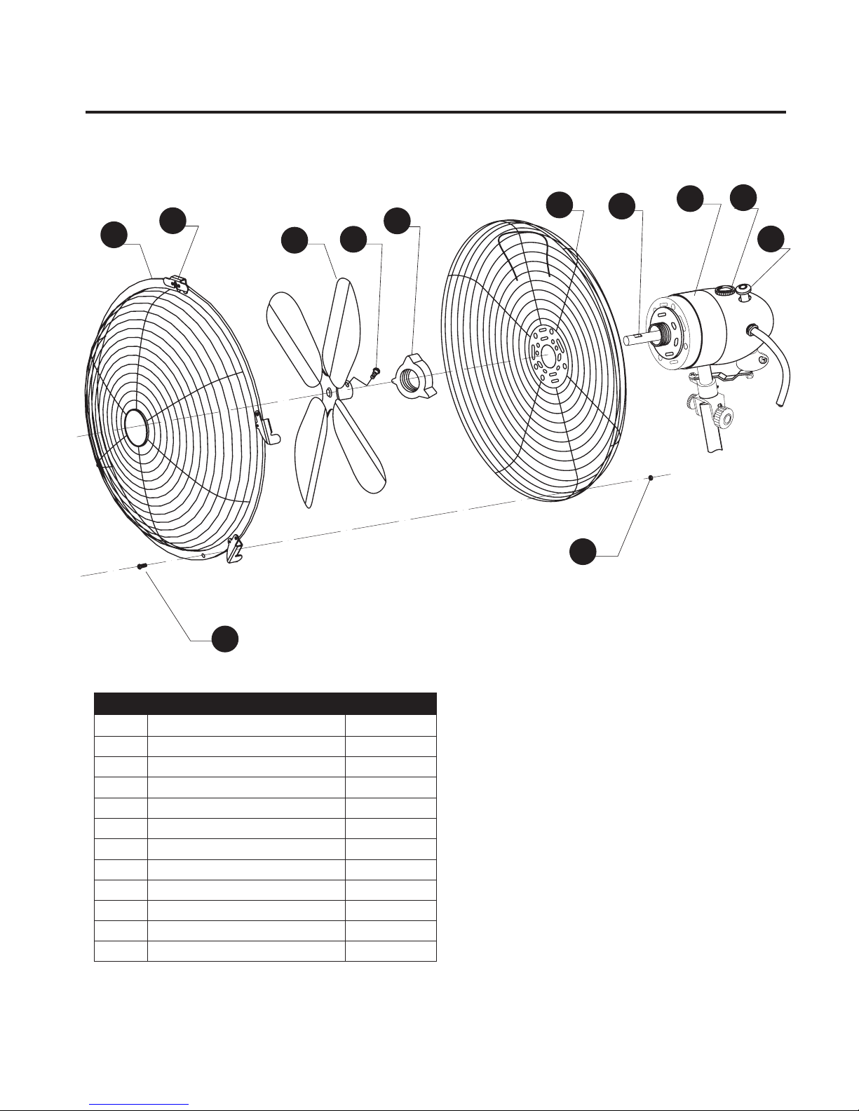
14
CONTENU DE L’EMBALLAGE
Instructions d’assemblage de la tête du ventilateur
X
9
Imprimé en Chine
Instructions d’assemblage de la tête du ventilateur
1. Retirez la vis de verrouillage sur la grille noire (C) de
l’ensemble du moteur (E).
2. Glissez la grille arrière (D) vers le devant de l’ensemble
du moteur (E) en gardant la poignée au centre supérieur.
3. Insérez la vis de verrouillage sur la grille noire (C) et
tournez dans le sens des aiguilles d’une montre pour la
serrer.
4.
Retirez la vis 5x8 (G) du tube reliant l’hélice du
ventilateur (B). Glissez l’hélice du ventilateur (B) sur
l’axe du moteur (H) ; réinsérez la vis 5x8 (G) et serrez
fermement.
5. Ouvrez tous les crochets qui se trouvent sur la grille
avant (A). Retirez la vis de sécurité (I) du bas de la grille
avant (A) et réservez-la sur le côté. Positionnez le crochet
de la grille (F) sur le centre supérieur de la grille noire (D)
et accrochez-le au cadre. Verrouillez tous les crochets
des grilles en pressant les deux grilles ensemble à
l’intérieur des crochets. Réintroduisez la vis de sécurité (I)
et vissez fermement.
1
2
3
5
4
INSTRUCTIONS
D'ASSAMBLAGE
VENTILATEUR CHEF
Des questions, des problèmes, des pièces manquantes? Avant de retourner l’article au
détaillant, appelez notre service à la clientèle au 1 800 979-4326, entre 8 h et 17 h (TVP), du
lundi au vendredi.
JOIGNEZ VOTRE REÇU ICI
Numéro de série Date d’achat
MODE D’EMPLOI
• Le bouton de commande de la vitesse (H) se trouve dans la
partie supérieure de l’arrière de l’ensemble de moteur de
ventilateur (J) (position 0 = arrêt, position I = vitesse lente,
position II = vitesse moyenne et position III = vitesse rapide).
Vous n’avez qu’à le faire tourner à la position souhaitée.
• Le ventilateur peut osciller ou rester immobile. Le bouton de
réglage de l’oscillation (I) se trouve dans la partie supérieure
de l’arrière de l’ensemble de moteur de ventilateur (J). Pour
mettre la fonction d’oscillation en marche, enfoncez
simplement le bouton. Pour l’arrêter, tirez le bouton.
• La tige supérieure (X) du ventilateur est télescopique.
Pour la régler à la hauteur désirée, desserrez puis
resserrez simplement la bague de réglage de la
hauteur (W).
• La tête de ventilateur peut également s’incliner légèrement.
Desserrez le bouton de réglage de l’inclinaison (K), inclinez
la tête de ventilateur selon l’angle désiré, puis resserrez le bouton.
ENTRETIEN
• Éteignez toujours le ventilateur avant de le nettoyer.
• Nettoyez les pièces à l’aide d’un plumeau, d’un linge doux ou d’une bonbonne d’air comprimé
(comme celle qui sert à nettoyer les ordinateurs). Avertissement : N’utilisez pas de solutions
nettoyantes ni de produits nettoyants abrasifs, car ils pourraient endommager le fini ou les
pièces du ventilateur.
Assurez-vous que l’interrupteur n’est pas sur la position d’arrêt (OFF).
Vérifiez que la fiche est bien branchée sur la prise.
Le ventilateur n’oscille
pas.
Appuyez sur le bouton de réglage de l’oscillation situé sur le haut du
moteur pour activer l’oscillation.
DÉPANNAGE
PROBLÉME MESURE CORRECTIVE
Le ventilateur ne
fonctionne pas.
Si vous avez des questions, veuillez téléphoner à notre service à la clientèle au
1 800 979-4326, entre 8 h et
17 h (TVP), du lundi au vendredi.
INSTRUCTIONS POUR L’ENTRETIEN
Ce produit est muni d’un dispositif permettant de prévenir la surchauffe (fusible). Un fusible grillé indique
une surcharge ou un court-circuit. Si un fusible grille, débranchez l’article. Remplacez le fusible
conformément aux instructions pour l’entretien (reportez-vous à l’article afin d’utiliser un fusible du
calibre approprié) et vérifiez le fonctionnement de l’article. Si le fusible de remplacement grille également,
il s’agit probablement d’un court-circuit; jetez l’article ou rapportez-le au centre de service agréé pour
inspection ou réparation.
1. Débranchez l’article en tirant sur la fiche.
Évitez de le débrancher en tirant sur le cordon
d’alimentation.
1
Prise
Fiche
Cordon d’alimentation
2. Ouvrez le compartiment à fusible en glissant le
couvercle d’accès au-dessus de la fiche de
branchement en direction des lames à l’aide d’un
tournevis à tête plate.
3. Retirez le fusible avec précaution en appuyant
doucement sur son extrémité à l’aide du tournevis
à tête plate et en tirant vers le haut. Afin de prévenir
les risques d’incendie, utilisez seulement les fusibles
de 5-ampères et 125-volts.
2
3
Tournevis
Fiche
Couvercle
d’accès
Fiche
Couvercle
d’accès
Fusible
(5 A)
4. Refermez le compartiment à fusible en glissant le
couvercle d’accès au-dessus de la fiche et rebranchez
la fiche sur la prise.
4
Fiche
Couvercle
d’accès
Fusible
(5 A)
GARANTIE
Garantie limitée de deux (2) ans
1. La présente garantie n’est offerte qu’au propriétaire initial de ce produit.
2. Cette garantie ne couvre que la réparation ou le remplacement des pièces défectueuses de ce
ventilateur. Le fabricant se réserve le droit de déterminer si la réparation ou le remplacement sont
couverts par la garantie.
3. Le fait de faire fonctionner ce ventilateur dans des conditions ou à des fins non spécifiées dans
les avertissements, le mode d’emploi ou les directives d’entretien du présent manuel peut entraîner
l’annulation de la garantie.
4. À moins d’une disposition contraire prévue à la loi, le fabricant ne peut être tenu responsable de
blessures ni de dommages matériels, accessoires ou consécutifs d’aucune sorte (y compris les
dégâts causés par l’eau), résultant d’un usage inapproprié, d’un défaut, d’une défaillance, d’une
installation inadéquate ou d’une modification du produit.
5. Toutes les pièces de ce produit sont garanties pour une période de deux (2) ans à compter
de la date d’achat.
6. Si le ventilateur présente un problème ou démontre une défaillance, veuillez communiquer avec
notre service à la clientèle au 1 800 979-4326, entre 8 h et 17 h (TVP), du lundi au vendredi.
7. Cette garantie vous confère des droits précis. Il est possible que vous disposiez également
d’autres droits, qui varient d’un État ou d’une province à l’autre. Les dispositions de la présente
garantie constituent un ajout aux garanties expresses et aux autres droits et garanties faisant partie
de toute loi applicable, sans qu’elles entraînent de modification ni de suppression d’aucune sorte.
Le cas échéant, toute disposition de la présente garantie sera considérée comme annulée ou
modifiée aux fins de conformité aux lois applicables.
H
I
J
6. La tête du ventilateur peut à présent être jointe à sa
base.
6
D
E
E
C
C
B
GH
AFD
IJ
A Grille avant du ventilateur 1
B Hélice 1
C
Grille arrière du ventilateur bague
1
D Grille arrière du ventilateur 1
E
Ensemble de moteur de ventilateur
1
F Fermoir de la grille 1
G M5x8 bague 1
H Arbre moteur 1
I M2.5x8 bague 1
J M2.5 Écrou 1
K
Bouton de commande de la vitesse
1
L
Bouton de réglage de l’oscillation
1
AF
BG
C
DHEK
L
J
I
PIÈCE DESCRIPTION QUANTITÉ
AA
Avant de commencer l’assemblage du produit, assurez-vous d’avoir toutes les pièces. Comparez les pièces
dans l’emballage avec la liste ci-dessus. S’il y a des pièces manquantes ou endommagées, ne tentez pas
d’assembler le produit. Communiquez avec le service à la clientèle pour obtenir des pièces de rechange.
Temps d’assemblage approximatif : de 10 à 15 minutes.
Outils nécessaires pour l’assemblage (non inclus) : tournevis cruciforme.
PRÉPARATION
CONSIGNES DE SÉCURITÉ
Assurez-vous de lire et de comprendre l’intégralité de ce manuel avant de tenter d’assembler, d’installer
ou d’utiliser le produit. Si vous avez des questions, veuillez téléphoner à notre service à la clientèle au
1 800 979-4326, entre 8 h et 17 h (TVP), du lundi au vendredi.
• Utilisez le ventilateur uniquement aux fins décrites dans le présent manuel.
• Ne faites pas fonctionner le ventilateur avant qu’il ne soit complètement assemblé.
• Assurez-vous d’utiliser la tension appropriée avant de brancher votre ventilateur (prise de 120 V c.a.).
• Débranchez le ventilateur de la prise lorsque vous ne l’utilisez pas, lorsque vous le déplacez ou avant
de le nettoyer.
• Ne touchez pas aux pièces en mouvement. N’insérez jamais vos doigts, des crayons ou tout autre objet
dans la grille pendant que le ventilateur fonctionne.
• Placez le ventilateur sur une surface stable et horizontale pour éviter de le faire basculer ou tomber
accidentellement.
• Afin de prévenir tout emmêlement accidentel, ne faites pas fonctionner le ventilateur directement à côté
de plantes, de rideaux ou de revêtements de fenêtres, entre autres.
• Même si votre ventilateur fonctionne à la plupart des températures, il est recommandé de le mettre
à couvert ou de le garder à l’intérieur de la maison lorsqu’il fait extrêmement froid ou que les précipitations
(de neige ou de pluie) sont abondantes.
• N’immergez pas votre ventilateur dans l’eau et gardez-le à une distance sécuritaire des piscines, des plans
d’eau et des arroseurs.
• N’utilisez pas un boyau d’arrosage ou un pulvérisateur à pression pour nettoyer votre ventilateur.
Reportez-vous à la section ENTRETIEN pour en savoir davantage sur le nettoyage du ventilateur.
• Pour éviter tout risque d’incendie, ne placez jamais le ventilateur ou son cordon d’alimentation sous un tapis.
• Ne couvrez pas le cordon avec une carpette, un tapis de passage ou un autre article semblable. Ne passez
pas le cordon sous des meubles ou des électroménagers. Ne placez pas le cordon dans un endroit achalandé
où il pourrait être accroché.
• Placez le cordon d’alimentation loin des endroits passants afin d’éviter que quelqu’un ne l’accroche ou
n’entre accidentellement en contact avec lui.
• Branchez ou débranchez toujours le cordon d’alimentation en empoignant la fiche. Ne tirez pas sur le cordon
d’alimentation.
• N’utilisez pas le ventilateur à proximité d’une flamme nue, ni en présence de vapeurs ou de gaz explosifs ou
inflammables.
• En cas de défectuosité ou de bris du ventilateur (ou de son cordon d’alimentation), cessez immédiatement
d’utiliser l’appareil jusqu’à ce qu’il soit réparé par un technicien qualifié.
• Gardez le ventilateur hors de la portée des enfants et des animaux.
• N’exposez pas directement les enfants et les personnes âgées à des courants d’air froid pendant de longues
périodes.
• Ne tentez jamais de démonter ni de modifier le produit contrairement aux indications du présent manuel.
RISQUE DE CHOC ÉLECTRIQUE
Ne branchez pas la fiche sur une prise avec les mains mouillées. Consultez le manuel
pour connaître les usages appropriés.
DANGER
Page 1
Page 2 Page 3
Page 4 Page 5
Page 6 Page 7 Page 8 Page 9
Page 10 Page 11
Page 12
NOTE: Start Canadian French section here,
followed by Latin American Spanish.
All covers will have page number.
100%
BLACK
FONT & SOFTWARE USAGE STATEMENT
COLOR USAGE & PRINT REQUIREMENTS
ALL INSTRUCTION MANUALS AND RELATED MATERIAL CREATED THROUGH
ADAPTATION OF THESE TEMPLATES MUST BE APPROVED BY LOWE’S
BRAND PACKAGING DEPARTMENT PRIOR TO PRODUCTION.
CONTACT: BRAND PACKAGING DEPARTMENT, LOWE’S COMPANIES, INC.
ATTN: PACKAGING STANDARDS
1000 LOWE’S BOULEVARD, MAIL STOP: 4WTD
MOORESVILLE, NC 28117
704-758-2785
DO NOT USE ANY COLOR GRAPHICS OR PHOTOGRAPHY IN YOUR INSTRUCTION
MANUALS. INSTRUCTION MANUALS PRINT IN GREYSCALE ONLY.
ALL GRAPHICS SHOWN ARE FOR SIZE AND POSITION ONLY; FINAL LINE-ART GRAPHICS
ARE REQUIRED FOR RELEASE TO PRESS.
IMPORTANT VENDOR NOTE
VENDORS ARE RESPONSIBLE FOR THE EXECUTION AND ACCURACY OF THEIR
INSTRUCTION MANUALS. THEY ARE SOLELY RESPONSIBLE FOR INSERTING ALL OF THE
CORRECT LEGAL CERTIFICATION, WARNING, WARRANTY, AND OTHER APPLICABLE
PRODUCT INFORMATION. HARDWARE MUST BE SHOWN AS ACTUAL SIZE IN THE
HARDWARE CONTENTS SECTION WITH LINE ART DRAWING OF THE HARDWARE, THE
DIMENSIONS, NAME DESCRIPTOR AND QUANTITY. LOWE’S IS NOT RESPONSIBLE FOR
ANY INCURRED DESIGN, TRANSLATION OR PRINTING COSTS. PLEASE REFER TO THE
TRANSLATION REQUIREMENTS ON LOWESLINK.COM
• FONTS USED ON THIS FILE: SEE FONT LEGEND.
• CONTACT YOUR APPROPRIATE FONT VENDOR TO PURCHASE THE REQUIRED FONTS
FOR THIS PACKAGE LINE.
• ADOBE ILLUSTRATOR CS3 WAS USED TO CREATE THIS FILE.
LOWE’S REQUIRES EACH VENDOR TO OBTAIN THEIR OWN LINE-ART GRAPHICS. ALL INSTRUCTION MANUAL GRAPHICS WILL
BE APPROVED BY LOWE’S BRAND MANAGEMENT DURING PROOFING.
THIS DESIGN IS PROPRIETARY AND CONFIDENTIAL TO LOWE’S COMPANIES, INC. AND CANNOT BE COPIED OR OTHERWISE
REPRODUCED OR USED WITHOUT THE EXPRESS WRITTEN PERMISSION OF LOWE’S.
THESE ARE THE PANTONE COLORS THAT ARE USED IN THIS FILE.
THESE MUST BE USED WHEN CREATING ANY OTHER PACKAGING.
THE ADDITION OF OTHER SPOT COLORS IS NOT PERMITTED.
ARTWORK DISCLAIMERS
FONT LEGEND
ALL FONTS MUST BE ARIAL BOLD OR ARIAL REGULAR, 12 PT. (MINIMUM) ON 14 PT. LEADING UNLESS OTHERWISE SPECIFIED.
REQUIRED PAPER TYPE
USE THE FOLLOWING PAPER FOR YOUR INSTRUCTION MANUALS:
• PAPER BASIS WEIGHT: 20-lb. PAPER OR 75 GRAMS/SQ METER
• DOCUMENT SIZE: PRINTED TWO-SIDES ON TABLOID OR A3 AND FOLDS
TO LETTER SIZE OR A4. INCLUDE SAMPLE MOCK-UP TO INDICATE
FOLD(S) AND PAGE LAYOUT.
THIS COLOR IS USED FOR
NOTES AND DOES NOT
PRINT.
CALL OUTS
(DO NOT PRINT)
THIS COLOR INDICATES
ALL TEXT TO BE CHANGED
WITH PRODUCT SPECIFIC
TEXT.
EDITABLE TEXT
(DO NOT PRINT)

15
B
A
Ensemble de moteur de ventilateur
1
B Ampoule 1
C Bague de blocage 1
CONTENU DE L’EMBALLAGE
Remplacement de l’ampoule du ventilateur en mosaïques de verre
X
9
Imprimé en Chine
Remplacement de l’ampoule du ventilateur en mosaïques de verre
1. Dévissez et retirez l’écrou à oreilles (C) du bas de la
base de l’ampoule du ventilateur.
2. Glissez avec précaution la tête du ventilateur (A) de
sa base et de la pièce centrale en mosaïques de verre
pour atteindre la douille de la lampe (B).
3. Dévissez et retirez l’ampoule (B). Remplacez-la.
4.
Réinsérez avec précaution la tête du ventilateur (A)
à travers la pièce centrale en mosaïques de verre et
dans la base du ventilateur.
5. Rattachez et serrez fermement l’écrou à oreilles (C)
pour compléter le processus d’assemblage.
1
2
3
5
4
C
A
A
B
A
C
H
I
J
A
B
C
AA
Avant de commencer l’assemblage du produit, assurez-vous d’avoir toutes les pièces. Comparez les pièces
dans l’emballage avec la liste ci-dessus. S’il y a des pièces manquantes ou endommagées, ne tentez pas
d’assembler le produit. Communiquez avec le service à la clientèle pour obtenir des pièces de rechange.
Temps d’assemblage approximatif : de 10 à 15 minutes.
Outils nécessaires pour l’assemblage (non inclus) : tournevis cruciforme.
PRÉPARATION
CONSIGNES DE SÉCURITÉ
Assurez-vous de lire et de comprendre l’intégralité de ce manuel avant de tenter d’assembler, d’installer
ou d’utiliser le produit. Si vous avez des questions, veuillez téléphoner à notre service à la clientèle au
1 800 979-4326, entre 8 h et 17 h (TVP), du lundi au vendredi.
• Utilisez le ventilateur uniquement aux fins décrites dans le présent manuel.
• Ne faites pas fonctionner le ventilateur avant qu’il ne soit complètement assemblé.
• Assurez-vous d’utiliser la tension appropriée avant de brancher votre ventilateur (prise de 120 V c.a.).
• Débranchez le ventilateur de la prise lorsque vous ne l’utilisez pas, lorsque vous le déplacez ou avant
de le nettoyer.
• Ne touchez pas aux pièces en mouvement. N’insérez jamais vos doigts, des crayons ou tout autre objet
dans la grille pendant que le ventilateur fonctionne.
• Placez le ventilateur sur une surface stable et horizontale pour éviter de le faire basculer ou tomber
accidentellement.
• Afin de prévenir tout emmêlement accidentel, ne faites pas fonctionner le ventilateur directement à côté
de plantes, de rideaux ou de revêtements de fenêtres, entre autres.
• Même si votre ventilateur fonctionne à la plupart des températures, il est recommandé de le mettre
à couvert ou de le garder à l’intérieur de la maison lorsqu’il fait extrêmement froid ou que les précipitations
(de neige ou de pluie) sont abondantes.
• N’immergez pas votre ventilateur dans l’eau et gardez-le à une distance sécuritaire des piscines, des plans
d’eau et des arroseurs.
• N’utilisez pas un boyau d’arrosage ou un pulvérisateur à pression pour nettoyer votre ventilateur.
Reportez-vous à la section ENTRETIEN pour en savoir davantage sur le nettoyage du ventilateur.
• Pour éviter tout risque d’incendie, ne placez jamais le ventilateur ou son cordon d’alimentation sous un tapis.
• Ne couvrez pas le cordon avec une carpette, un tapis de passage ou un autre article semblable. Ne passez
pas le cordon sous des meubles ou des électroménagers. Ne placez pas le cordon dans un endroit achalandé
où il pourrait être accroché.
• Placez le cordon d’alimentation loin des endroits passants afin d’éviter que quelqu’un ne l’accroche ou
n’entre accidentellement en contact avec lui.
• Branchez ou débranchez toujours le cordon d’alimentation en empoignant la fiche. Ne tirez pas sur le cordon
d’alimentation.
• N’utilisez pas le ventilateur à proximité d’une flamme nue, ni en présence de vapeurs ou de gaz explosifs ou
inflammables.
• En cas de défectuosité ou de bris du ventilateur (ou de son cordon d’alimentation), cessez immédiatement
d’utiliser l’appareil jusqu’à ce qu’il soit réparé par un technicien qualifié.
• Gardez le ventilateur hors de la portée des enfants et des animaux.
• N’exposez pas directement les enfants et les personnes âgées à des courants d’air froid pendant de longues
périodes.
• Ne tentez jamais de démonter ni de modifier le produit contrairement aux indications du présent manuel.
RISQUE DE CHOC ÉLECTRIQUE
Ne branchez pas la fiche sur une prise avec les mains mouillées. Consultez le manuel
pour connaître les usages appropriés.
DANGER
TABLE
VENTILATEUR
DÉCORATIFS
HAUT
Des questions, des problèmes, des pièces manquantes? Avant de retourner l’article au
détaillant, appelez notre service à la clientèle au 1 800 979-4326, entre 8 h et 17 h (TVP), du
lundi au vendredi.
JOIGNEZ VOTRE REÇU ICI
Numéro de série Date d’achat
PIÈCE DESCRIPTION QUANTITÉ
MODE D’EMPLOI
• Le bouton de commande de la vitesse (H) se trouve dans la
partie supérieure de l’arrière de l’ensemble de moteur de
ventilateur (J) (position 0 = arrêt, position I = vitesse lente,
position II = vitesse moyenne et position III = vitesse rapide).
Vous n’avez qu’à le faire tourner à la position souhaitée.
• Le ventilateur peut osciller ou rester immobile. Le bouton de
réglage de l’oscillation (I) se trouve dans la partie supérieure
de l’arrière de l’ensemble de moteur de ventilateur (J). Pour
mettre la fonction d’oscillation en marche, enfoncez
simplement le bouton. Pour l’arrêter, tirez le bouton.
• La tige supérieure (X) du ventilateur est télescopique.
Pour la régler à la hauteur désirée, desserrez puis
resserrez simplement la bague de réglage de la
hauteur (W).
• La tête de ventilateur peut également s’incliner légèrement.
Desserrez le bouton de réglage de l’inclinaison (K), inclinez
la tête de ventilateur selon l’angle désiré, puis resserrez le bouton.
ENTRETIEN
• Éteignez toujours le ventilateur avant de le nettoyer.
• Nettoyez les pièces à l’aide d’un plumeau, d’un linge doux ou d’une bonbonne d’air comprimé
(comme celle qui sert à nettoyer les ordinateurs). Avertissement : N’utilisez pas de solutions
nettoyantes ni de produits nettoyants abrasifs, car ils pourraient endommager le fini ou les
pièces du ventilateur.
Assurez-vous que l’interrupteur n’est pas sur la position d’arrêt (OFF).
Vérifiez que la fiche est bien branchée sur la prise.
Le ventilateur n’oscille
pas.
Appuyez sur le bouton de réglage de l’oscillation situé sur le haut du
moteur pour activer l’oscillation.
DÉPANNAGE
PROBLÉME MESURE CORRECTIVE
Le ventilateur ne
fonctionne pas.
Si vous avez des questions, veuillez téléphoner à notre service à la clientèle au
1 800 979-4326, entre 8 h et
17 h (TVP), du lundi au vendredi.
INSTRUCTIONS POUR L’ENTRETIEN
Ce produit est muni d’un dispositif permettant de prévenir la surchauffe (fusible). Un fusible grillé indique
une surcharge ou un court-circuit. Si un fusible grille, débranchez l’article. Remplacez le fusible
conformément aux instructions pour l’entretien (reportez-vous à l’article afin d’utiliser un fusible du
calibre approprié) et vérifiez le fonctionnement de l’article. Si le fusible de remplacement grille également,
il s’agit probablement d’un court-circuit; jetez l’article ou rapportez-le au centre de service agréé pour
inspection ou réparation.
1. Débranchez l’article en tirant sur la fiche.
Évitez de le débrancher en tirant sur le cordon
d’alimentation.
1
Prise
Fiche
Cordon d’alimentation
2. Ouvrez le compartiment à fusible en glissant le
couvercle d’accès au-dessus de la fiche de
branchement en direction des lames à l’aide d’un
tournevis à tête plate.
3. Retirez le fusible avec précaution en appuyant
doucement sur son extrémité à l’aide du tournevis
à tête plate et en tirant vers le haut. Afin de prévenir
les risques d’incendie, utilisez seulement les fusibles
de 5-ampères et 125-volts.
2
3
Tournevis
Fiche
Couvercle
d’accès
Fiche
Couvercle
d’accès
Fusible
(5 A)
4. Refermez le compartiment à fusible en glissant le
couvercle d’accès au-dessus de la fiche et rebranchez
la fiche sur la prise.
4
Fiche
Couvercle
d’accès
Fusible
(5 A)
GARANTIE
Garantie limitée de deux (2) ans
1. La présente garantie n’est offerte qu’au propriétaire initial de ce produit.
2. Cette garantie ne couvre que la réparation ou le remplacement des pièces défectueuses de ce
ventilateur. Le fabricant se réserve le droit de déterminer si la réparation ou le remplacement sont
couverts par la garantie.
3. Le fait de faire fonctionner ce ventilateur dans des conditions ou à des fins non spécifiées dans
les avertissements, le mode d’emploi ou les directives d’entretien du présent manuel peut entraîner
l’annulation de la garantie.
4. À moins d’une disposition contraire prévue à la loi, le fabricant ne peut être tenu responsable de
blessures ni de dommages matériels, accessoires ou consécutifs d’aucune sorte (y compris les
dégâts causés par l’eau), résultant d’un usage inapproprié, d’un défaut, d’une défaillance, d’une
installation inadéquate ou d’une modification du produit.
5. Toutes les pièces de ce produit sont garanties pour une période de deux (2) ans à compter
de la date d’achat.
6. Si le ventilateur présente un problème ou démontre une défaillance, veuillez communiquer avec
notre service à la clientèle au 1 800 979-4326, entre 8 h et 17 h (TVP), du lundi au vendredi.
7. Cette garantie vous confère des droits précis. Il est possible que vous disposiez également
d’autres droits, qui varient d’un État ou d’une province à l’autre. Les dispositions de la présente
garantie constituent un ajout aux garanties expresses et aux autres droits et garanties faisant partie
de toute loi applicable, sans qu’elles entraînent de modification ni de suppression d’aucune sorte.
Le cas échéant, toute disposition de la présente garantie sera considérée comme annulée ou
modifiée aux fins de conformité aux lois applicables.
Page 1
Page 2 Page 3
Page 4 Page 5
Page 6 Page 7 Page 8 Page 9
Page 10 Page 11
Page 12
NOTE: Start Canadian French section here,
followed by Latin American Spanish.
All covers will have page number.
100%
BLACK
FONT & SOFTWARE USAGE STATEMENT
COLOR USAGE & PRINT REQUIREMENTS
ALL INSTRUCTION MANUALS AND RELATED MATERIAL CREATED THROUGH
ADAPTATION OF THESE TEMPLATES MUST BE APPROVED BY LOWE’S
BRAND PACKAGING DEPARTMENT PRIOR TO PRODUCTION.
CONTACT: BRAND PACKAGING DEPARTMENT, LOWE’S COMPANIES, INC.
ATTN: PACKAGING STANDARDS
1000 LOWE’S BOULEVARD, MAIL STOP: 4WTD
MOORESVILLE, NC 28117
704-758-2785
DO NOT USE ANY COLOR GRAPHICS OR PHOTOGRAPHY IN YOUR INSTRUCTION
MANUALS. INSTRUCTION MANUALS PRINT IN GREYSCALE ONLY.
ALL GRAPHICS SHOWN ARE FOR SIZE AND POSITION ONLY; FINAL LINE-ART GRAPHICS
ARE REQUIRED FOR RELEASE TO PRESS.
IMPORTANT VENDOR NOTE
VENDORS ARE RESPONSIBLE FOR THE EXECUTION AND ACCURACY OF THEIR
INSTRUCTION MANUALS. THEY ARE SOLELY RESPONSIBLE FOR INSERTING ALL OF THE
CORRECT LEGAL CERTIFICATION, WARNING, WARRANTY, AND OTHER APPLICABLE
PRODUCT INFORMATION. HARDWARE MUST BE SHOWN AS ACTUAL SIZE IN THE
HARDWARE CONTENTS SECTION WITH LINE ART DRAWING OF THE HARDWARE, THE
DIMENSIONS, NAME DESCRIPTOR AND QUANTITY. LOWE’S IS NOT RESPONSIBLE FOR
ANY INCURRED DESIGN, TRANSLATION OR PRINTING COSTS. PLEASE REFER TO THE
TRANSLATION REQUIREMENTS ON LOWESLINK.COM
• FONTS USED ON THIS FILE: SEE FONT LEGEND.
• CONTACT YOUR APPROPRIATE FONT VENDOR TO PURCHASE THE REQUIRED FONTS
FOR THIS PACKAGE LINE.
• ADOBE ILLUSTRATOR CS3 WAS USED TO CREATE THIS FILE.
LOWE’S REQUIRES EACH VENDOR TO OBTAIN THEIR OWN LINE-ART GRAPHICS. ALL INSTRUCTION MANUAL GRAPHICS WILL
BE APPROVED BY LOWE’S BRAND MANAGEMENT DURING PROOFING.
THIS DESIGN IS PROPRIETARY AND CONFIDENTIAL TO LOWE’S COMPANIES, INC. AND CANNOT BE COPIED OR OTHERWISE
REPRODUCED OR USED WITHOUT THE EXPRESS WRITTEN PERMISSION OF LOWE’S.
THESE ARE THE PANTONE COLORS THAT ARE USED IN THIS FILE.
THESE MUST BE USED WHEN CREATING ANY OTHER PACKAGING.
THE ADDITION OF OTHER SPOT COLORS IS NOT PERMITTED.
ARTWORK DISCLAIMERS
FONT LEGEND
ALL FONTS MUST BE ARIAL BOLD OR ARIAL REGULAR, 12 PT. (MINIMUM) ON 14 PT. LEADING UNLESS OTHERWISE SPECIFIED.
REQUIRED PAPER TYPE
USE THE FOLLOWING PAPER FOR YOUR INSTRUCTION MANUALS:
• PAPER BASIS WEIGHT: 20-lb. PAPER OR 75 GRAMS/SQ METER
• DOCUMENT SIZE: PRINTED TWO-SIDES ON TABLOID OR A3 AND FOLDS
TO LETTER SIZE OR A4. INCLUDE SAMPLE MOCK-UP TO INDICATE
FOLD(S) AND PAGE LAYOUT.
THIS COLOR IS USED FOR
NOTES AND DOES NOT
PRINT.
CALL OUTS
(DO NOT PRINT)
THIS COLOR INDICATES
ALL TEXT TO BE CHANGED
WITH PRODUCT SPECIFIC
TEXT.
EDITABLE TEXT
(DO NOT PRINT)

16
CONTENU DE L’EMBALLAGE
Instructions d’assemblage de la tête du ventilateur
X
9
Imprimé en Chine
Instructions d’assemblage de la tête du ventilateur
1. Retirez la vis de verrouillage sur la grille noire (C) de
l’ensemble du moteur (E).
2. Glissez la grille arrière (D) vers le devant de l’ensemble
du moteur (E) en gardant la poignée au centre supérieur.
3. Insérez la vis de verrouillage sur la grille noire (C) et
tournez dans le sens des aiguilles d’une montre pour la
serrer.
4.
Retirez la vis 5x8 (G) du tube reliant l’hélice du
ventilateur (B). Glissez l’hélice du ventilateur (B) sur
l’axe du moteur (H) ; réinsérez la vis 5x8 (G) et serrez
fermement.
5. Ouvrez tous les crochets qui se trouvent sur la grille
avant (A). Retirez la vis de sécurité (I) du bas de la grille
avant (A) et réservez-la sur le côté. Positionnez le crochet
de la grille (F) sur le centre supérieur de la grille noire (D)
et accrochez-le au cadre. Verrouillez tous les crochets
des grilles en pressant les deux grilles ensemble à
l’intérieur des crochets. Réintroduisez la vis de sécurité (I)
et vissez fermement.
1
2
3
5
4
INSTRUCTIONS
D'ASSAMBLAGE
VENTILATEUR CHEF
Des questions, des problèmes, des pièces manquantes? Avant de retourner l’article au
détaillant, appelez notre service à la clientèle au 1 800 979-4326, entre 8 h et 17 h (TVP), du
lundi au vendredi.
JOIGNEZ VOTRE REÇU ICI
Numéro de série Date d’achat
MODE D’EMPLOI
• Le bouton de commande de la vitesse (H) se trouve dans la
partie supérieure de l’arrière de l’ensemble de moteur de
ventilateur (J) (position 0 = arrêt, position I = vitesse lente,
position II = vitesse moyenne et position III = vitesse rapide).
Vous n’avez qu’à le faire tourner à la position souhaitée.
• Le ventilateur peut osciller ou rester immobile. Le bouton de
réglage de l’oscillation (I) se trouve dans la partie supérieure
de l’arrière de l’ensemble de moteur de ventilateur (J). Pour
mettre la fonction d’oscillation en marche, enfoncez
simplement le bouton. Pour l’arrêter, tirez le bouton.
• La tige supérieure (X) du ventilateur est télescopique.
Pour la régler à la hauteur désirée, desserrez puis
resserrez simplement la bague de réglage de la
hauteur (W).
• La tête de ventilateur peut également s’incliner légèrement.
Desserrez le bouton de réglage de l’inclinaison (K), inclinez
la tête de ventilateur selon l’angle désiré, puis resserrez le bouton.
ENTRETIEN
• Éteignez toujours le ventilateur avant de le nettoyer.
• Nettoyez les pièces à l’aide d’un plumeau, d’un linge doux ou d’une bonbonne d’air comprimé
(comme celle qui sert à nettoyer les ordinateurs). Avertissement : N’utilisez pas de solutions
nettoyantes ni de produits nettoyants abrasifs, car ils pourraient endommager le fini ou les
pièces du ventilateur.
Assurez-vous que l’interrupteur n’est pas sur la position d’arrêt (OFF).
Vérifiez que la fiche est bien branchée sur la prise.
Le ventilateur n’oscille
pas.
Appuyez sur le bouton de réglage de l’oscillation situé sur le haut du
moteur pour activer l’oscillation.
DÉPANNAGE
PROBLÉME MESURE CORRECTIVE
Le ventilateur ne
fonctionne pas.
Si vous avez des questions, veuillez téléphoner à notre service à la clientèle au
1 800 979-4326, entre 8 h et
17 h (TVP), du lundi au vendredi.
INSTRUCTIONS POUR L’ENTRETIEN
Ce produit est muni d’un dispositif permettant de prévenir la surchauffe (fusible). Un fusible grillé indique
une surcharge ou un court-circuit. Si un fusible grille, débranchez l’article. Remplacez le fusible
conformément aux instructions pour l’entretien (reportez-vous à l’article afin d’utiliser un fusible du
calibre approprié) et vérifiez le fonctionnement de l’article. Si le fusible de remplacement grille également,
il s’agit probablement d’un court-circuit; jetez l’article ou rapportez-le au centre de service agréé pour
inspection ou réparation.
1. Débranchez l’article en tirant sur la fiche.
Évitez de le débrancher en tirant sur le cordon
d’alimentation.
1
Prise
Fiche
Cordon d’alimentation
2. Ouvrez le compartiment à fusible en glissant le
couvercle d’accès au-dessus de la fiche de
branchement en direction des lames à l’aide d’un
tournevis à tête plate.
3. Retirez le fusible avec précaution en appuyant
doucement sur son extrémité à l’aide du tournevis
à tête plate et en tirant vers le haut. Afin de prévenir
les risques d’incendie, utilisez seulement les fusibles
de 5-ampères et 125-volts.
2
3
Tournevis
Fiche
Couvercle
d’accès
Fiche
Couvercle
d’accès
Fusible
(5 A)
4. Refermez le compartiment à fusible en glissant le
couvercle d’accès au-dessus de la fiche et rebranchez
la fiche sur la prise.
4
Fiche
Couvercle
d’accès
Fusible
(5 A)
GARANTIE
Garantie limitée de deux (2) ans
1. La présente garantie n’est offerte qu’au propriétaire initial de ce produit.
2. Cette garantie ne couvre que la réparation ou le remplacement des pièces défectueuses de ce
ventilateur. Le fabricant se réserve le droit de déterminer si la réparation ou le remplacement sont
couverts par la garantie.
3. Le fait de faire fonctionner ce ventilateur dans des conditions ou à des fins non spécifiées dans
les avertissements, le mode d’emploi ou les directives d’entretien du présent manuel peut entraîner
l’annulation de la garantie.
4. À moins d’une disposition contraire prévue à la loi, le fabricant ne peut être tenu responsable de
blessures ni de dommages matériels, accessoires ou consécutifs d’aucune sorte (y compris les
dégâts causés par l’eau), résultant d’un usage inapproprié, d’un défaut, d’une défaillance, d’une
installation inadéquate ou d’une modification du produit.
5. Toutes les pièces de ce produit sont garanties pour une période de deux (2) ans à compter
de la date d’achat.
6. Si le ventilateur présente un problème ou démontre une défaillance, veuillez communiquer avec
notre service à la clientèle au 1 800 979-4326, entre 8 h et 17 h (TVP), du lundi au vendredi.
7. Cette garantie vous confère des droits précis. Il est possible que vous disposiez également
d’autres droits, qui varient d’un État ou d’une province à l’autre. Les dispositions de la présente
garantie constituent un ajout aux garanties expresses et aux autres droits et garanties faisant partie
de toute loi applicable, sans qu’elles entraînent de modification ni de suppression d’aucune sorte.
Le cas échéant, toute disposition de la présente garantie sera considérée comme annulée ou
modifiée aux fins de conformité aux lois applicables.
H
I
J
6. La tête du ventilateur peut à présent être jointe à sa
base. 6
D
E
E
C
C
B
GH
AFD
IJ
A Grille avant du ventilateur 1
B Hélice 1
C
Grille arrière du ventilateur bague
1
D Grille arrière du ventilateur 1
E Ensemble de moteur de ventilateur 1
F Fermoir de la grille 1
G M5x8 bague 1
H Arbre moteur 1
I M2.5x8 bague 1
J M2.5 Écrou 1
K Bouton de commande de la vitesse 1
L
Bouton de réglage de l’oscillation
1
AF
BG
C
DHEK
L
J
I
PIÈCE DESCRIPTION QUANTITÉ
AA
Avant de commencer l’assemblage du produit, assurez-vous d’avoir toutes les pièces. Comparez les pièces
dans l’emballage avec la liste ci-dessus. S’il y a des pièces manquantes ou endommagées, ne tentez pas
d’assembler le produit. Communiquez avec le service à la clientèle pour obtenir des pièces de rechange.
Temps d’assemblage approximatif : de 10 à 15 minutes.
Outils nécessaires pour l’assemblage (non inclus) : tournevis cruciforme.
PRÉPARATION
CONSIGNES DE SÉCURITÉ
Assurez-vous de lire et de comprendre l’intégralité de ce manuel avant de tenter d’assembler, d’installer
ou d’utiliser le produit. Si vous avez des questions, veuillez téléphoner à notre service à la clientèle au
1 800 979-4326, entre 8 h et 17 h (TVP), du lundi au vendredi.
• Utilisez le ventilateur uniquement aux fins décrites dans le présent manuel.
• Ne faites pas fonctionner le ventilateur avant qu’il ne soit complètement assemblé.
• Assurez-vous d’utiliser la tension appropriée avant de brancher votre ventilateur (prise de 120 V c.a.).
• Débranchez le ventilateur de la prise lorsque vous ne l’utilisez pas, lorsque vous le déplacez ou avant
de le nettoyer.
• Ne touchez pas aux pièces en mouvement. N’insérez jamais vos doigts, des crayons ou tout autre objet
dans la grille pendant que le ventilateur fonctionne.
• Placez le ventilateur sur une surface stable et horizontale pour éviter de le faire basculer ou tomber
accidentellement.
• Afin de prévenir tout emmêlement accidentel, ne faites pas fonctionner le ventilateur directement à côté
de plantes, de rideaux ou de revêtements de fenêtres, entre autres.
• Même si votre ventilateur fonctionne à la plupart des températures, il est recommandé de le mettre
à couvert ou de le garder à l’intérieur de la maison lorsqu’il fait extrêmement froid ou que les précipitations
(de neige ou de pluie) sont abondantes.
• N’immergez pas votre ventilateur dans l’eau et gardez-le à une distance sécuritaire des piscines, des plans
d’eau et des arroseurs.
• N’utilisez pas un boyau d’arrosage ou un pulvérisateur à pression pour nettoyer votre ventilateur.
Reportez-vous à la section ENTRETIEN pour en savoir davantage sur le nettoyage du ventilateur.
• Pour éviter tout risque d’incendie, ne placez jamais le ventilateur ou son cordon d’alimentation sous un tapis.
• Ne couvrez pas le cordon avec une carpette, un tapis de passage ou un autre article semblable. Ne passez
pas le cordon sous des meubles ou des électroménagers. Ne placez pas le cordon dans un endroit achalandé
où il pourrait être accroché.
• Placez le cordon d’alimentation loin des endroits passants afin d’éviter que quelqu’un ne l’accroche ou
n’entre accidentellement en contact avec lui.
• Branchez ou débranchez toujours le cordon d’alimentation en empoignant la fiche. Ne tirez pas sur le cordon
d’alimentation.
• N’utilisez pas le ventilateur à proximité d’une flamme nue, ni en présence de vapeurs ou de gaz explosifs ou
inflammables.
• En cas de défectuosité ou de bris du ventilateur (ou de son cordon d’alimentation), cessez immédiatement
d’utiliser l’appareil jusqu’à ce qu’il soit réparé par un technicien qualifié.
• Gardez le ventilateur hors de la portée des enfants et des animaux.
• N’exposez pas directement les enfants et les personnes âgées à des courants d’air froid pendant de longues
périodes.
• Ne tentez jamais de démonter ni de modifier le produit contrairement aux indications du présent manuel.
RISQUE DE CHOC ÉLECTRIQUE
Ne branchez pas la fiche sur une prise avec les mains mouillées. Consultez le manuel
pour connaître les usages appropriés.
DANGER
Page 1
Page 2 Page 3
Page 4 Page 5
Page 6 Page 7 Page 8 Page 9
Page 10 Page 11
Page 12
NOTE: Start Canadian French section here,
followed by Latin American Spanish.
All covers will have page number.
100%
BLACK
FONT & SOFTWARE USAGE STATEMENT
COLOR USAGE & PRINT REQUIREMENTS
ALL INSTRUCTION MANUALS AND RELATED MATERIAL CREATED THROUGH
ADAPTATION OF THESE TEMPLATES MUST BE APPROVED BY LOWE’S
BRAND PACKAGING DEPARTMENT PRIOR TO PRODUCTION.
CONTACT: BRAND PACKAGING DEPARTMENT, LOWE’S COMPANIES, INC.
ATTN: PACKAGING STANDARDS
1000 LOWE’S BOULEVARD, MAIL STOP: 4WTD
MOORESVILLE, NC 28117
704-758-2785
DO NOT USE ANY COLOR GRAPHICS OR PHOTOGRAPHY IN YOUR INSTRUCTION
MANUALS. INSTRUCTION MANUALS PRINT IN GREYSCALE ONLY.
ALL GRAPHICS SHOWN ARE FOR SIZE AND POSITION ONLY; FINAL LINE-ART GRAPHICS
ARE REQUIRED FOR RELEASE TO PRESS.
IMPORTANT VENDOR NOTE
VENDORS ARE RESPONSIBLE FOR THE EXECUTION AND ACCURACY OF THEIR
INSTRUCTION MANUALS. THEY ARE SOLELY RESPONSIBLE FOR INSERTING ALL OF THE
CORRECT LEGAL CERTIFICATION, WARNING, WARRANTY, AND OTHER APPLICABLE
PRODUCT INFORMATION. HARDWARE MUST BE SHOWN AS ACTUAL SIZE IN THE
HARDWARE CONTENTS SECTION WITH LINE ART DRAWING OF THE HARDWARE, THE
DIMENSIONS, NAME DESCRIPTOR AND QUANTITY. LOWE’S IS NOT RESPONSIBLE FOR
ANY INCURRED DESIGN, TRANSLATION OR PRINTING COSTS. PLEASE REFER TO THE
TRANSLATION REQUIREMENTS ON LOWESLINK.COM
• FONTS USED ON THIS FILE: SEE FONT LEGEND.
• CONTACT YOUR APPROPRIATE FONT VENDOR TO PURCHASE THE REQUIRED FONTS
FOR THIS PACKAGE LINE.
• ADOBE ILLUSTRATOR CS3 WAS USED TO CREATE THIS FILE.
LOWE’S REQUIRES EACH VENDOR TO OBTAIN THEIR OWN LINE-ART GRAPHICS. ALL INSTRUCTION MANUAL GRAPHICS WILL
BE APPROVED BY LOWE’S BRAND MANAGEMENT DURING PROOFING.
THIS DESIGN IS PROPRIETARY AND CONFIDENTIAL TO LOWE’S COMPANIES, INC. AND CANNOT BE COPIED OR OTHERWISE
REPRODUCED OR USED WITHOUT THE EXPRESS WRITTEN PERMISSION OF LOWE’S.
THESE ARE THE PANTONE COLORS THAT ARE USED IN THIS FILE.
THESE MUST BE USED WHEN CREATING ANY OTHER PACKAGING.
THE ADDITION OF OTHER SPOT COLORS IS NOT PERMITTED.
ARTWORK DISCLAIMERS
FONT LEGEND
ALL FONTS MUST BE ARIAL BOLD OR ARIAL REGULAR, 12 PT. (MINIMUM) ON 14 PT. LEADING UNLESS OTHERWISE SPECIFIED.
REQUIRED PAPER TYPE
USE THE FOLLOWING PAPER FOR YOUR INSTRUCTION MANUALS:
• PAPER BASIS WEIGHT: 20-lb. PAPER OR 75 GRAMS/SQ METER
• DOCUMENT SIZE: PRINTED TWO-SIDES ON TABLOID OR A3 AND FOLDS
TO LETTER SIZE OR A4. INCLUDE SAMPLE MOCK-UP TO INDICATE
FOLD(S) AND PAGE LAYOUT.
THIS COLOR IS USED FOR
NOTES AND DOES NOT
PRINT.
CALL OUTS
(DO NOT PRINT)
THIS COLOR INDICATES
ALL TEXT TO BE CHANGED
WITH PRODUCT SPECIFIC
TEXT.
EDITABLE TEXT
(DO NOT PRINT)

17
CONTENU DE L’EMBALLAGE
Instructions d’assemblage de la tête du ventilateur
X
9
Imprimé en Chine
Instructions d’assemblage de la tête du ventilateur
1. Retirez la vis de verrouillage sur la grille noire (C) de
l’ensemble du moteur (E).
2. Glissez la grille arrière (D) vers le devant de l’ensemble
du moteur (E) en gardant la poignée au centre supérieur.
3. Insérez la vis de verrouillage sur la grille noire (C) et
tournez dans le sens des aiguilles d’une montre pour la
serrer.
4.
Retirez la vis 5x8 (G) du tube reliant l’hélice du
ventilateur (B). Glissez l’hélice du ventilateur (B) sur
l’axe du moteur (H) ; réinsérez la vis 5x8 (G) et serrez
fermement.
5. Ouvrez tous les crochets qui se trouvent sur la grille
avant (A). Retirez la vis de sécurité (I) du bas de la grille
avant (A) et réservez-la sur le côté. Positionnez le crochet
de la grille (F) sur le centre supérieur de la grille noire (D)
et accrochez-le au cadre. Verrouillez tous les crochets
des grilles en pressant les deux grilles ensemble à
l’intérieur des crochets. Réintroduisez la vis de sécurité (I)
et vissez fermement.
1
2
3
5
4
INSTRUCTIONS
D'ASSAMBLAGE
VENTILATEUR CHEF
Des questions, des problèmes, des pièces manquantes? Avant de retourner l’article au
détaillant, appelez notre service à la clientèle au 1 800 979-4326, entre 8 h et 17 h (TVP), du
lundi au vendredi.
JOIGNEZ VOTRE REÇU ICI
Numéro de série Date d’achat
MODE D’EMPLOI
• Le bouton de commande de la vitesse (H) se trouve dans la
partie supérieure de l’arrière de l’ensemble de moteur de
ventilateur (J) (position 0 = arrêt, position I = vitesse lente,
position II = vitesse moyenne et position III = vitesse rapide).
Vous n’avez qu’à le faire tourner à la position souhaitée.
• Le ventilateur peut osciller ou rester immobile. Le bouton de
réglage de l’oscillation (I) se trouve dans la partie supérieure
de l’arrière de l’ensemble de moteur de ventilateur (J). Pour
mettre la fonction d’oscillation en marche, enfoncez
simplement le bouton. Pour l’arrêter, tirez le bouton.
• La tige supérieure (X) du ventilateur est télescopique.
Pour la régler à la hauteur désirée, desserrez puis
resserrez simplement la bague de réglage de la
hauteur (W).
• La tête de ventilateur peut également s’incliner légèrement.
Desserrez le bouton de réglage de l’inclinaison (K), inclinez
la tête de ventilateur selon l’angle désiré, puis resserrez le bouton.
ENTRETIEN
• Éteignez toujours le ventilateur avant de le nettoyer.
• Nettoyez les pièces à l’aide d’un plumeau, d’un linge doux ou d’une bonbonne d’air comprimé
(comme celle qui sert à nettoyer les ordinateurs). Avertissement : N’utilisez pas de solutions
nettoyantes ni de produits nettoyants abrasifs, car ils pourraient endommager le fini ou les
pièces du ventilateur.
Assurez-vous que l’interrupteur n’est pas sur la position d’arrêt (OFF).
Vérifiez que la fiche est bien branchée sur la prise.
Le ventilateur n’oscille
pas.
Appuyez sur le bouton de réglage de l’oscillation situé sur le haut du
moteur pour activer l’oscillation.
DÉPANNAGE
PROBLÉME MESURE CORRECTIVE
Le ventilateur ne
fonctionne pas.
Si vous avez des questions, veuillez téléphoner à notre service à la clientèle au
1 800 979-4326, entre 8 h et
17 h (TVP), du lundi au vendredi.
INSTRUCTIONS POUR L’ENTRETIEN
Ce produit est muni d’un dispositif permettant de prévenir la surchauffe (fusible). Un fusible grillé indique
une surcharge ou un court-circuit. Si un fusible grille, débranchez l’article. Remplacez le fusible
conformément aux instructions pour l’entretien (reportez-vous à l’article afin d’utiliser un fusible du
calibre approprié) et vérifiez le fonctionnement de l’article. Si le fusible de remplacement grille également,
il s’agit probablement d’un court-circuit; jetez l’article ou rapportez-le au centre de service agréé pour
inspection ou réparation.
1. Débranchez l’article en tirant sur la fiche.
Évitez de le débrancher en tirant sur le cordon
d’alimentation.
1
Prise
Fiche
Cordon d’alimentation
2. Ouvrez le compartiment à fusible en glissant le
couvercle d’accès au-dessus de la fiche de
branchement en direction des lames à l’aide d’un
tournevis à tête plate.
3. Retirez le fusible avec précaution en appuyant
doucement sur son extrémité à l’aide du tournevis
à tête plate et en tirant vers le haut. Afin de prévenir
les risques d’incendie, utilisez seulement les fusibles
de 5-ampères et 125-volts.
2
3
Tournevis
Fiche
Couvercle
d’accès
Fiche
Couvercle
d’accès
Fusible
(5 A)
4. Refermez le compartiment à fusible en glissant le
couvercle d’accès au-dessus de la fiche et rebranchez
la fiche sur la prise.
4
Fiche
Couvercle
d’accès
Fusible
(5 A)
GARANTIE
Garantie limitée de deux (2) ans
1. La présente garantie n’est offerte qu’au propriétaire initial de ce produit.
2. Cette garantie ne couvre que la réparation ou le remplacement des pièces défectueuses de ce
ventilateur. Le fabricant se réserve le droit de déterminer si la réparation ou le remplacement sont
couverts par la garantie.
3. Le fait de faire fonctionner ce ventilateur dans des conditions ou à des fins non spécifiées dans
les avertissements, le mode d’emploi ou les directives d’entretien du présent manuel peut entraîner
l’annulation de la garantie.
4. À moins d’une disposition contraire prévue à la loi, le fabricant ne peut être tenu responsable de
blessures ni de dommages matériels, accessoires ou consécutifs d’aucune sorte (y compris les
dégâts causés par l’eau), résultant d’un usage inapproprié, d’un défaut, d’une défaillance, d’une
installation inadéquate ou d’une modification du produit.
5. Toutes les pièces de ce produit sont garanties pour une période de deux (2) ans à compter
de la date d’achat.
6. Si le ventilateur présente un problème ou démontre une défaillance, veuillez communiquer avec
notre service à la clientèle au 1 800 979-4326, entre 8 h et 17 h (TVP), du lundi au vendredi.
7. Cette garantie vous confère des droits précis. Il est possible que vous disposiez également
d’autres droits, qui varient d’un État ou d’une province à l’autre. Les dispositions de la présente
garantie constituent un ajout aux garanties expresses et aux autres droits et garanties faisant partie
de toute loi applicable, sans qu’elles entraînent de modification ni de suppression d’aucune sorte.
Le cas échéant, toute disposition de la présente garantie sera considérée comme annulée ou
modifiée aux fins de conformité aux lois applicables.
H
I
J
6. La tête du ventilateur peut à présent être jointe à sa
base.
6
D
E
E
C
C
B
GH
AFD
IJ
A Grille avant du ventilateur 1
B Hélice 1
C
Grille arrière du ventilateur bague
1
D Grille arrière du ventilateur 1
E
Ensemble de moteur de ventilateur
1
F Fermoir de la grille 1
G M5x8 bague 1
H Arbre moteur 1
I M2.5x8 bague 1
J M2.5 Écrou 1
K
Bouton de commande de la vitesse
1
L
Bouton de réglage de l’oscillation
1
AF
BG
C
DHEK
L
J
I
PIÈCE DESCRIPTION QUANTITÉ
AA
Avant de commencer l’assemblage du produit, assurez-vous d’avoir toutes les pièces. Comparez les pièces
dans l’emballage avec la liste ci-dessus. S’il y a des pièces manquantes ou endommagées, ne tentez pas
d’assembler le produit. Communiquez avec le service à la clientèle pour obtenir des pièces de rechange.
Temps d’assemblage approximatif : de 10 à 15 minutes.
Outils nécessaires pour l’assemblage (non inclus) : tournevis cruciforme.
PRÉPARATION
CONSIGNES DE SÉCURITÉ
Assurez-vous de lire et de comprendre l’intégralité de ce manuel avant de tenter d’assembler, d’installer
ou d’utiliser le produit. Si vous avez des questions, veuillez téléphoner à notre service à la clientèle au
1 800 979-4326, entre 8 h et 17 h (TVP), du lundi au vendredi.
• Utilisez le ventilateur uniquement aux fins décrites dans le présent manuel.
• Ne faites pas fonctionner le ventilateur avant qu’il ne soit complètement assemblé.
• Assurez-vous d’utiliser la tension appropriée avant de brancher votre ventilateur (prise de 120 V c.a.).
• Débranchez le ventilateur de la prise lorsque vous ne l’utilisez pas, lorsque vous le déplacez ou avant
de le nettoyer.
• Ne touchez pas aux pièces en mouvement. N’insérez jamais vos doigts, des crayons ou tout autre objet
dans la grille pendant que le ventilateur fonctionne.
• Placez le ventilateur sur une surface stable et horizontale pour éviter de le faire basculer ou tomber
accidentellement.
• Afin de prévenir tout emmêlement accidentel, ne faites pas fonctionner le ventilateur directement à côté
de plantes, de rideaux ou de revêtements de fenêtres, entre autres.
• Même si votre ventilateur fonctionne à la plupart des températures, il est recommandé de le mettre
à couvert ou de le garder à l’intérieur de la maison lorsqu’il fait extrêmement froid ou que les précipitations
(de neige ou de pluie) sont abondantes.
• N’immergez pas votre ventilateur dans l’eau et gardez-le à une distance sécuritaire des piscines, des plans
d’eau et des arroseurs.
• N’utilisez pas un boyau d’arrosage ou un pulvérisateur à pression pour nettoyer votre ventilateur.
Reportez-vous à la section ENTRETIEN pour en savoir davantage sur le nettoyage du ventilateur.
• Pour éviter tout risque d’incendie, ne placez jamais le ventilateur ou son cordon d’alimentation sous un tapis.
• Ne couvrez pas le cordon avec une carpette, un tapis de passage ou un autre article semblable. Ne passez
pas le cordon sous des meubles ou des électroménagers. Ne placez pas le cordon dans un endroit achalandé
où il pourrait être accroché.
• Placez le cordon d’alimentation loin des endroits passants afin d’éviter que quelqu’un ne l’accroche ou
n’entre accidentellement en contact avec lui.
• Branchez ou débranchez toujours le cordon d’alimentation en empoignant la fiche. Ne tirez pas sur le cordon
d’alimentation.
• N’utilisez pas le ventilateur à proximité d’une flamme nue, ni en présence de vapeurs ou de gaz explosifs ou
inflammables.
• En cas de défectuosité ou de bris du ventilateur (ou de son cordon d’alimentation), cessez immédiatement
d’utiliser l’appareil jusqu’à ce qu’il soit réparé par un technicien qualifié.
• Gardez le ventilateur hors de la portée des enfants et des animaux.
• N’exposez pas directement les enfants et les personnes âgées à des courants d’air froid pendant de longues
périodes.
• Ne tentez jamais de démonter ni de modifier le produit contrairement aux indications du présent manuel.
RISQUE DE CHOC ÉLECTRIQUE
Ne branchez pas la fiche sur une prise avec les mains mouillées. Consultez le manuel
pour connaître les usages appropriés.
DANGER
Page 1
Page 2 Page 3
Page 4 Page 5
Page 6 Page 7 Page 8 Page 9
Page 10 Page 11
Page 12
NOTE: Start Canadian French section here,
followed by Latin American Spanish.
All covers will have page number.
100%
BLACK
FONT & SOFTWARE USAGE STATEMENT
COLOR USAGE & PRINT REQUIREMENTS
ALL INSTRUCTION MANUALS AND RELATED MATERIAL CREATED THROUGH
ADAPTATION OF THESE TEMPLATES MUST BE APPROVED BY LOWE’S
BRAND PACKAGING DEPARTMENT PRIOR TO PRODUCTION.
CONTACT: BRAND PACKAGING DEPARTMENT, LOWE’S COMPANIES, INC.
ATTN: PACKAGING STANDARDS
1000 LOWE’S BOULEVARD, MAIL STOP: 4WTD
MOORESVILLE, NC 28117
704-758-2785
DO NOT USE ANY COLOR GRAPHICS OR PHOTOGRAPHY IN YOUR INSTRUCTION
MANUALS. INSTRUCTION MANUALS PRINT IN GREYSCALE ONLY.
ALL GRAPHICS SHOWN ARE FOR SIZE AND POSITION ONLY; FINAL LINE-ART GRAPHICS
ARE REQUIRED FOR RELEASE TO PRESS.
IMPORTANT VENDOR NOTE
VENDORS ARE RESPONSIBLE FOR THE EXECUTION AND ACCURACY OF THEIR
INSTRUCTION MANUALS. THEY ARE SOLELY RESPONSIBLE FOR INSERTING ALL OF THE
CORRECT LEGAL CERTIFICATION, WARNING, WARRANTY, AND OTHER APPLICABLE
PRODUCT INFORMATION. HARDWARE MUST BE SHOWN AS ACTUAL SIZE IN THE
HARDWARE CONTENTS SECTION WITH LINE ART DRAWING OF THE HARDWARE, THE
DIMENSIONS, NAME DESCRIPTOR AND QUANTITY. LOWE’S IS NOT RESPONSIBLE FOR
ANY INCURRED DESIGN, TRANSLATION OR PRINTING COSTS. PLEASE REFER TO THE
TRANSLATION REQUIREMENTS ON LOWESLINK.COM
• FONTS USED ON THIS FILE: SEE FONT LEGEND.
• CONTACT YOUR APPROPRIATE FONT VENDOR TO PURCHASE THE REQUIRED FONTS
FOR THIS PACKAGE LINE.
• ADOBE ILLUSTRATOR CS3 WAS USED TO CREATE THIS FILE.
LOWE’S REQUIRES EACH VENDOR TO OBTAIN THEIR OWN LINE-ART GRAPHICS. ALL INSTRUCTION MANUAL GRAPHICS WILL
BE APPROVED BY LOWE’S BRAND MANAGEMENT DURING PROOFING.
THIS DESIGN IS PROPRIETARY AND CONFIDENTIAL TO LOWE’S COMPANIES, INC. AND CANNOT BE COPIED OR OTHERWISE
REPRODUCED OR USED WITHOUT THE EXPRESS WRITTEN PERMISSION OF LOWE’S.
THESE ARE THE PANTONE COLORS THAT ARE USED IN THIS FILE.
THESE MUST BE USED WHEN CREATING ANY OTHER PACKAGING.
THE ADDITION OF OTHER SPOT COLORS IS NOT PERMITTED.
ARTWORK DISCLAIMERS
FONT LEGEND
ALL FONTS MUST BE ARIAL BOLD OR ARIAL REGULAR, 12 PT. (MINIMUM) ON 14 PT. LEADING UNLESS OTHERWISE SPECIFIED.
REQUIRED PAPER TYPE
USE THE FOLLOWING PAPER FOR YOUR INSTRUCTION MANUALS:
• PAPER BASIS WEIGHT: 20-lb. PAPER OR 75 GRAMS/SQ METER
• DOCUMENT SIZE: PRINTED TWO-SIDES ON TABLOID OR A3 AND FOLDS
TO LETTER SIZE OR A4. INCLUDE SAMPLE MOCK-UP TO INDICATE
FOLD(S) AND PAGE LAYOUT.
THIS COLOR IS USED FOR
NOTES AND DOES NOT
PRINT.
CALL OUTS
(DO NOT PRINT)
THIS COLOR INDICATES
ALL TEXT TO BE CHANGED
WITH PRODUCT SPECIFIC
TEXT.
EDITABLE TEXT
(DO NOT PRINT)

18
B
A
Ensemble de moteur de ventilateur
1
B Ampoule 1
C Bague de blocage 1
CONTENU DE L’EMBALLAGE
Remplacement de l’ampoule du ventilateur en mosaïques de verre
X
9
Imprimé en Chine
Remplacement de l’ampoule du ventilateur en mosaïques de verre
1. Dévissez et retirez l’écrou à oreilles (C) du bas de la
base de l’ampoule du ventilateur.
2. Glissez avec précaution la tête du ventilateur (A) de
sa base et de la pièce centrale en mosaïques de verre
pour atteindre la douille de la lampe (B).
3. Dévissez et retirez l’ampoule (B). Remplacez-la.
4.
Réinsérez avec précaution la tête du ventilateur (A)
à travers la pièce centrale en mosaïques de verre et
dans la base du ventilateur.
5. Rattachez et serrez fermement l’écrou à oreilles (C)
pour compléter le processus d’assemblage.
1
2
3
5
4
C
A
A
B
A
C
H
I
J
A
B
C
AA
Avant de commencer l’assemblage du produit, assurez-vous d’avoir toutes les pièces. Comparez les pièces
dans l’emballage avec la liste ci-dessus. S’il y a des pièces manquantes ou endommagées, ne tentez pas
d’assembler le produit. Communiquez avec le service à la clientèle pour obtenir des pièces de rechange.
Temps d’assemblage approximatif : de 10 à 15 minutes.
Outils nécessaires pour l’assemblage (non inclus) : tournevis cruciforme.
PRÉPARATION
CONSIGNES DE SÉCURITÉ
Assurez-vous de lire et de comprendre l’intégralité de ce manuel avant de tenter d’assembler, d’installer
ou d’utiliser le produit. Si vous avez des questions, veuillez téléphoner à notre service à la clientèle au
1 800 979-4326, entre 8 h et 17 h (TVP), du lundi au vendredi.
• Utilisez le ventilateur uniquement aux fins décrites dans le présent manuel.
• Ne faites pas fonctionner le ventilateur avant qu’il ne soit complètement assemblé.
• Assurez-vous d’utiliser la tension appropriée avant de brancher votre ventilateur (prise de 120 V c.a.).
• Débranchez le ventilateur de la prise lorsque vous ne l’utilisez pas, lorsque vous le déplacez ou avant
de le nettoyer.
• Ne touchez pas aux pièces en mouvement. N’insérez jamais vos doigts, des crayons ou tout autre objet
dans la grille pendant que le ventilateur fonctionne.
• Placez le ventilateur sur une surface stable et horizontale pour éviter de le faire basculer ou tomber
accidentellement.
• Afin de prévenir tout emmêlement accidentel, ne faites pas fonctionner le ventilateur directement à côté
de plantes, de rideaux ou de revêtements de fenêtres, entre autres.
• Même si votre ventilateur fonctionne à la plupart des températures, il est recommandé de le mettre
à couvert ou de le garder à l’intérieur de la maison lorsqu’il fait extrêmement froid ou que les précipitations
(de neige ou de pluie) sont abondantes.
• N’immergez pas votre ventilateur dans l’eau et gardez-le à une distance sécuritaire des piscines, des plans
d’eau et des arroseurs.
• N’utilisez pas un boyau d’arrosage ou un pulvérisateur à pression pour nettoyer votre ventilateur.
Reportez-vous à la section ENTRETIEN pour en savoir davantage sur le nettoyage du ventilateur.
• Pour éviter tout risque d’incendie, ne placez jamais le ventilateur ou son cordon d’alimentation sous un tapis.
• Ne couvrez pas le cordon avec une carpette, un tapis de passage ou un autre article semblable. Ne passez
pas le cordon sous des meubles ou des électroménagers. Ne placez pas le cordon dans un endroit achalandé
où il pourrait être accroché.
• Placez le cordon d’alimentation loin des endroits passants afin d’éviter que quelqu’un ne l’accroche ou
n’entre accidentellement en contact avec lui.
• Branchez ou débranchez toujours le cordon d’alimentation en empoignant la fiche. Ne tirez pas sur le cordon
d’alimentation.
• N’utilisez pas le ventilateur à proximité d’une flamme nue, ni en présence de vapeurs ou de gaz explosifs ou
inflammables.
• En cas de défectuosité ou de bris du ventilateur (ou de son cordon d’alimentation), cessez immédiatement
d’utiliser l’appareil jusqu’à ce qu’il soit réparé par un technicien qualifié.
• Gardez le ventilateur hors de la portée des enfants et des animaux.
• N’exposez pas directement les enfants et les personnes âgées à des courants d’air froid pendant de longues
périodes.
• Ne tentez jamais de démonter ni de modifier le produit contrairement aux indications du présent manuel.
RISQUE DE CHOC ÉLECTRIQUE
Ne branchez pas la fiche sur une prise avec les mains mouillées. Consultez le manuel
pour connaître les usages appropriés.
DANGER
TABLE
VENTILATEUR
DÉCORATIFS
HAUT
Des questions, des problèmes, des pièces manquantes? Avant de retourner l’article au
détaillant, appelez notre service à la clientèle au 1 800 979-4326, entre 8 h et 17 h (TVP), du
lundi au vendredi.
JOIGNEZ VOTRE REÇU ICI
Numéro de série Date d’achat
PIÈCE DESCRIPTION QUANTITÉ
MODE D’EMPLOI
• Le bouton de commande de la vitesse (H) se trouve dans la
partie supérieure de l’arrière de l’ensemble de moteur de
ventilateur (J) (position 0 = arrêt, position I = vitesse lente,
position II = vitesse moyenne et position III = vitesse rapide).
Vous n’avez qu’à le faire tourner à la position souhaitée.
• Le ventilateur peut osciller ou rester immobile. Le bouton de
réglage de l’oscillation (I) se trouve dans la partie supérieure
de l’arrière de l’ensemble de moteur de ventilateur (J). Pour
mettre la fonction d’oscillation en marche, enfoncez
simplement le bouton. Pour l’arrêter, tirez le bouton.
• La tige supérieure (X) du ventilateur est télescopique.
Pour la régler à la hauteur désirée, desserrez puis
resserrez simplement la bague de réglage de la
hauteur (W).
• La tête de ventilateur peut également s’incliner légèrement.
Desserrez le bouton de réglage de l’inclinaison (K), inclinez
la tête de ventilateur selon l’angle désiré, puis resserrez le bouton.
ENTRETIEN
• Éteignez toujours le ventilateur avant de le nettoyer.
• Nettoyez les pièces à l’aide d’un plumeau, d’un linge doux ou d’une bonbonne d’air comprimé
(comme celle qui sert à nettoyer les ordinateurs). Avertissement : N’utilisez pas de solutions
nettoyantes ni de produits nettoyants abrasifs, car ils pourraient endommager le fini ou les
pièces du ventilateur.
Assurez-vous que l’interrupteur n’est pas sur la position d’arrêt (OFF).
Vérifiez que la fiche est bien branchée sur la prise.
Le ventilateur n’oscille
pas.
Appuyez sur le bouton de réglage de l’oscillation situé sur le haut du
moteur pour activer l’oscillation.
DÉPANNAGE
PROBLÉME MESURE CORRECTIVE
Le ventilateur ne
fonctionne pas.
Si vous avez des questions, veuillez téléphoner à notre service à la clientèle au
1 800 979-4326, entre 8 h et
17 h (TVP), du lundi au vendredi.
INSTRUCTIONS POUR L’ENTRETIEN
Ce produit est muni d’un dispositif permettant de prévenir la surchauffe (fusible). Un fusible grillé indique
une surcharge ou un court-circuit. Si un fusible grille, débranchez l’article. Remplacez le fusible
conformément aux instructions pour l’entretien (reportez-vous à l’article afin d’utiliser un fusible du
calibre approprié) et vérifiez le fonctionnement de l’article. Si le fusible de remplacement grille également,
il s’agit probablement d’un court-circuit; jetez l’article ou rapportez-le au centre de service agréé pour
inspection ou réparation.
1. Débranchez l’article en tirant sur la fiche.
Évitez de le débrancher en tirant sur le cordon
d’alimentation.
1
Prise
Fiche
Cordon d’alimentation
2. Ouvrez le compartiment à fusible en glissant le
couvercle d’accès au-dessus de la fiche de
branchement en direction des lames à l’aide d’un
tournevis à tête plate.
3. Retirez le fusible avec précaution en appuyant
doucement sur son extrémité à l’aide du tournevis
à tête plate et en tirant vers le haut. Afin de prévenir
les risques d’incendie, utilisez seulement les fusibles
de 5-ampères et 125-volts.
2
3
Tournevis
Fiche
Couvercle
d’accès
Fiche
Couvercle
d’accès
Fusible
(5 A)
4. Refermez le compartiment à fusible en glissant le
couvercle d’accès au-dessus de la fiche et rebranchez
la fiche sur la prise.
4
Fiche
Couvercle
d’accès
Fusible
(5 A)
GARANTIE
Garantie limitée de deux (2) ans
1. La présente garantie n’est offerte qu’au propriétaire initial de ce produit.
2. Cette garantie ne couvre que la réparation ou le remplacement des pièces défectueuses de ce
ventilateur. Le fabricant se réserve le droit de déterminer si la réparation ou le remplacement sont
couverts par la garantie.
3. Le fait de faire fonctionner ce ventilateur dans des conditions ou à des fins non spécifiées dans
les avertissements, le mode d’emploi ou les directives d’entretien du présent manuel peut entraîner
l’annulation de la garantie.
4. À moins d’une disposition contraire prévue à la loi, le fabricant ne peut être tenu responsable de
blessures ni de dommages matériels, accessoires ou consécutifs d’aucune sorte (y compris les
dégâts causés par l’eau), résultant d’un usage inapproprié, d’un défaut, d’une défaillance, d’une
installation inadéquate ou d’une modification du produit.
5. Toutes les pièces de ce produit sont garanties pour une période de deux (2) ans à compter
de la date d’achat.
6. Si le ventilateur présente un problème ou démontre une défaillance, veuillez communiquer avec
notre service à la clientèle au 1 800 979-4326, entre 8 h et 17 h (TVP), du lundi au vendredi.
7. Cette garantie vous confère des droits précis. Il est possible que vous disposiez également
d’autres droits, qui varient d’un État ou d’une province à l’autre. Les dispositions de la présente
garantie constituent un ajout aux garanties expresses et aux autres droits et garanties faisant partie
de toute loi applicable, sans qu’elles entraînent de modification ni de suppression d’aucune sorte.
Le cas échéant, toute disposition de la présente garantie sera considérée comme annulée ou
modifiée aux fins de conformité aux lois applicables.
Page 1
Page 2 Page 3
Page 4 Page 5
Page 6 Page 7 Page 8 Page 9
Page 10 Page 11
Page 12
NOTE: Start Canadian French section here,
followed by Latin American Spanish.
All covers will have page number.
100%
BLACK
FONT & SOFTWARE USAGE STATEMENT
COLOR USAGE & PRINT REQUIREMENTS
ALL INSTRUCTION MANUALS AND RELATED MATERIAL CREATED THROUGH
ADAPTATION OF THESE TEMPLATES MUST BE APPROVED BY LOWE’S
BRAND PACKAGING DEPARTMENT PRIOR TO PRODUCTION.
CONTACT: BRAND PACKAGING DEPARTMENT, LOWE’S COMPANIES, INC.
ATTN: PACKAGING STANDARDS
1000 LOWE’S BOULEVARD, MAIL STOP: 4WTD
MOORESVILLE, NC 28117
704-758-2785
DO NOT USE ANY COLOR GRAPHICS OR PHOTOGRAPHY IN YOUR INSTRUCTION
MANUALS. INSTRUCTION MANUALS PRINT IN GREYSCALE ONLY.
ALL GRAPHICS SHOWN ARE FOR SIZE AND POSITION ONLY; FINAL LINE-ART GRAPHICS
ARE REQUIRED FOR RELEASE TO PRESS.
IMPORTANT VENDOR NOTE
VENDORS ARE RESPONSIBLE FOR THE EXECUTION AND ACCURACY OF THEIR
INSTRUCTION MANUALS. THEY ARE SOLELY RESPONSIBLE FOR INSERTING ALL OF THE
CORRECT LEGAL CERTIFICATION, WARNING, WARRANTY, AND OTHER APPLICABLE
PRODUCT INFORMATION. HARDWARE MUST BE SHOWN AS ACTUAL SIZE IN THE
HARDWARE CONTENTS SECTION WITH LINE ART DRAWING OF THE HARDWARE, THE
DIMENSIONS, NAME DESCRIPTOR AND QUANTITY. LOWE’S IS NOT RESPONSIBLE FOR
ANY INCURRED DESIGN, TRANSLATION OR PRINTING COSTS. PLEASE REFER TO THE
TRANSLATION REQUIREMENTS ON LOWESLINK.COM
• FONTS USED ON THIS FILE: SEE FONT LEGEND.
• CONTACT YOUR APPROPRIATE FONT VENDOR TO PURCHASE THE REQUIRED FONTS
FOR THIS PACKAGE LINE.
• ADOBE ILLUSTRATOR CS3 WAS USED TO CREATE THIS FILE.
LOWE’S REQUIRES EACH VENDOR TO OBTAIN THEIR OWN LINE-ART GRAPHICS. ALL INSTRUCTION MANUAL GRAPHICS WILL
BE APPROVED BY LOWE’S BRAND MANAGEMENT DURING PROOFING.
THIS DESIGN IS PROPRIETARY AND CONFIDENTIAL TO LOWE’S COMPANIES, INC. AND CANNOT BE COPIED OR OTHERWISE
REPRODUCED OR USED WITHOUT THE EXPRESS WRITTEN PERMISSION OF LOWE’S.
THESE ARE THE PANTONE COLORS THAT ARE USED IN THIS FILE.
THESE MUST BE USED WHEN CREATING ANY OTHER PACKAGING.
THE ADDITION OF OTHER SPOT COLORS IS NOT PERMITTED.
ARTWORK DISCLAIMERS
FONT LEGEND
ALL FONTS MUST BE ARIAL BOLD OR ARIAL REGULAR, 12 PT. (MINIMUM) ON 14 PT. LEADING UNLESS OTHERWISE SPECIFIED.
REQUIRED PAPER TYPE
USE THE FOLLOWING PAPER FOR YOUR INSTRUCTION MANUALS:
• PAPER BASIS WEIGHT: 20-lb. PAPER OR 75 GRAMS/SQ METER
• DOCUMENT SIZE: PRINTED TWO-SIDES ON TABLOID OR A3 AND FOLDS
TO LETTER SIZE OR A4. INCLUDE SAMPLE MOCK-UP TO INDICATE
FOLD(S) AND PAGE LAYOUT.
THIS COLOR IS USED FOR
NOTES AND DOES NOT
PRINT.
CALL OUTS
(DO NOT PRINT)
THIS COLOR INDICATES
ALL TEXT TO BE CHANGED
WITH PRODUCT SPECIFIC
TEXT.
EDITABLE TEXT
(DO NOT PRINT)

19
B
A
Ensemble de moteur de ventilateur
1
B Ampoule 1
C Bague de blocage 1
CONTENU DE L’EMBALLAGE
Remplacement de l’ampoule du ventilateur en mosaïques de verre
X
9
Imprimé en Chine
Remplacement de l’ampoule du ventilateur en mosaïques de verre
1. Dévissez et retirez l’écrou à oreilles (C) du bas de la
base de l’ampoule du ventilateur.
2. Glissez avec précaution la tête du ventilateur (A) de
sa base et de la pièce centrale en mosaïques de verre
pour atteindre la douille de la lampe (B).
3. Dévissez et retirez l’ampoule (B). Remplacez-la.
4.
Réinsérez avec précaution la tête du ventilateur (A)
à travers la pièce centrale en mosaïques de verre et
dans la base du ventilateur.
5. Rattachez et serrez fermement l’écrou à oreilles (C)
pour compléter le processus d’assemblage.
1
2
3
5
4
C
A
A
B
A
C
H
I
J
A
B
C
AA
Avant de commencer l’assemblage du produit, assurez-vous d’avoir toutes les pièces. Comparez les pièces
dans l’emballage avec la liste ci-dessus. S’il y a des pièces manquantes ou endommagées, ne tentez pas
d’assembler le produit. Communiquez avec le service à la clientèle pour obtenir des pièces de rechange.
Temps d’assemblage approximatif : de 10 à 15 minutes.
Outils nécessaires pour l’assemblage (non inclus) : tournevis cruciforme.
PRÉPARATION
CONSIGNES DE SÉCURITÉ
Assurez-vous de lire et de comprendre l’intégralité de ce manuel avant de tenter d’assembler, d’installer
ou d’utiliser le produit. Si vous avez des questions, veuillez téléphoner à notre service à la clientèle au
1 800 979-4326, entre 8 h et 17 h (TVP), du lundi au vendredi.
• Utilisez le ventilateur uniquement aux fins décrites dans le présent manuel.
• Ne faites pas fonctionner le ventilateur avant qu’il ne soit complètement assemblé.
• Assurez-vous d’utiliser la tension appropriée avant de brancher votre ventilateur (prise de 120 V c.a.).
• Débranchez le ventilateur de la prise lorsque vous ne l’utilisez pas, lorsque vous le déplacez ou avant
de le nettoyer.
• Ne touchez pas aux pièces en mouvement. N’insérez jamais vos doigts, des crayons ou tout autre objet
dans la grille pendant que le ventilateur fonctionne.
• Placez le ventilateur sur une surface stable et horizontale pour éviter de le faire basculer ou tomber
accidentellement.
• Afin de prévenir tout emmêlement accidentel, ne faites pas fonctionner le ventilateur directement à côté
de plantes, de rideaux ou de revêtements de fenêtres, entre autres.
• Même si votre ventilateur fonctionne à la plupart des températures, il est recommandé de le mettre
à couvert ou de le garder à l’intérieur de la maison lorsqu’il fait extrêmement froid ou que les précipitations
(de neige ou de pluie) sont abondantes.
• N’immergez pas votre ventilateur dans l’eau et gardez-le à une distance sécuritaire des piscines, des plans
d’eau et des arroseurs.
• N’utilisez pas un boyau d’arrosage ou un pulvérisateur à pression pour nettoyer votre ventilateur.
Reportez-vous à la section ENTRETIEN pour en savoir davantage sur le nettoyage du ventilateur.
• Pour éviter tout risque d’incendie, ne placez jamais le ventilateur ou son cordon d’alimentation sous un tapis.
• Ne couvrez pas le cordon avec une carpette, un tapis de passage ou un autre article semblable. Ne passez
pas le cordon sous des meubles ou des électroménagers. Ne placez pas le cordon dans un endroit achalandé
où il pourrait être accroché.
• Placez le cordon d’alimentation loin des endroits passants afin d’éviter que quelqu’un ne l’accroche ou
n’entre accidentellement en contact avec lui.
• Branchez ou débranchez toujours le cordon d’alimentation en empoignant la fiche. Ne tirez pas sur le cordon
d’alimentation.
• N’utilisez pas le ventilateur à proximité d’une flamme nue, ni en présence de vapeurs ou de gaz explosifs ou
inflammables.
• En cas de défectuosité ou de bris du ventilateur (ou de son cordon d’alimentation), cessez immédiatement
d’utiliser l’appareil jusqu’à ce qu’il soit réparé par un technicien qualifié.
• Gardez le ventilateur hors de la portée des enfants et des animaux.
• N’exposez pas directement les enfants et les personnes âgées à des courants d’air froid pendant de longues
périodes.
• Ne tentez jamais de démonter ni de modifier le produit contrairement aux indications du présent manuel.
RISQUE DE CHOC ÉLECTRIQUE
Ne branchez pas la fiche sur une prise avec les mains mouillées. Consultez le manuel
pour connaître les usages appropriés.
DANGER
TABLE
VENTILATEUR
DÉCORATIFS
HAUT
Des questions, des problèmes, des pièces manquantes? Avant de retourner l’article au
détaillant, appelez notre service à la clientèle au 1 800 979-4326, entre 8 h et 17 h (TVP), du
lundi au vendredi.
JOIGNEZ VOTRE REÇU ICI
Numéro de série Date d’achat
PIÈCE DESCRIPTION QUANTITÉ
MODE D’EMPLOI
• Le bouton de commande de la vitesse (H) se trouve dans la
partie supérieure de l’arrière de l’ensemble de moteur de
ventilateur (J) (position 0 = arrêt, position I = vitesse lente,
position II = vitesse moyenne et position III = vitesse rapide).
Vous n’avez qu’à le faire tourner à la position souhaitée.
• Le ventilateur peut osciller ou rester immobile. Le bouton de
réglage de l’oscillation (I) se trouve dans la partie supérieure
de l’arrière de l’ensemble de moteur de ventilateur (J). Pour
mettre la fonction d’oscillation en marche, enfoncez
simplement le bouton. Pour l’arrêter, tirez le bouton.
• La tige supérieure (X) du ventilateur est télescopique.
Pour la régler à la hauteur désirée, desserrez puis
resserrez simplement la bague de réglage de la
hauteur (W).
• La tête de ventilateur peut également s’incliner légèrement.
Desserrez le bouton de réglage de l’inclinaison (K), inclinez
la tête de ventilateur selon l’angle désiré, puis resserrez le bouton.
ENTRETIEN
• Éteignez toujours le ventilateur avant de le nettoyer.
• Nettoyez les pièces à l’aide d’un plumeau, d’un linge doux ou d’une bonbonne d’air comprimé
(comme celle qui sert à nettoyer les ordinateurs). Avertissement : N’utilisez pas de solutions
nettoyantes ni de produits nettoyants abrasifs, car ils pourraient endommager le fini ou les
pièces du ventilateur.
Assurez-vous que l’interrupteur n’est pas sur la position d’arrêt (OFF).
Vérifiez que la fiche est bien branchée sur la prise.
Le ventilateur n’oscille
pas.
Appuyez sur le bouton de réglage de l’oscillation situé sur le haut du
moteur pour activer l’oscillation.
DÉPANNAGE
PROBLÉME MESURE CORRECTIVE
Le ventilateur ne
fonctionne pas.
Si vous avez des questions, veuillez téléphoner à notre service à la clientèle au
1 800 979-4326, entre 8 h et
17 h (TVP), du lundi au vendredi.
INSTRUCTIONS POUR L’ENTRETIEN
Ce produit est muni d’un dispositif permettant de prévenir la surchauffe (fusible). Un fusible grillé indique
une surcharge ou un court-circuit. Si un fusible grille, débranchez l’article. Remplacez le fusible
conformément aux instructions pour l’entretien (reportez-vous à l’article afin d’utiliser un fusible du
calibre approprié) et vérifiez le fonctionnement de l’article. Si le fusible de remplacement grille également,
il s’agit probablement d’un court-circuit; jetez l’article ou rapportez-le au centre de service agréé pour
inspection ou réparation.
1. Débranchez l’article en tirant sur la fiche.
Évitez de le débrancher en tirant sur le cordon
d’alimentation.
1
Prise
Fiche
Cordon d’alimentation
2. Ouvrez le compartiment à fusible en glissant le
couvercle d’accès au-dessus de la fiche de
branchement en direction des lames à l’aide d’un
tournevis à tête plate.
3. Retirez le fusible avec précaution en appuyant
doucement sur son extrémité à l’aide du tournevis
à tête plate et en tirant vers le haut. Afin de prévenir
les risques d’incendie, utilisez seulement les fusibles
de 5-ampères et 125-volts.
2
3
Tournevis
Fiche
Couvercle
d’accès
Fiche
Couvercle
d’accès
Fusible
(5 A)
4. Refermez le compartiment à fusible en glissant le
couvercle d’accès au-dessus de la fiche et rebranchez
la fiche sur la prise.
4
Fiche
Couvercle
d’accès
Fusible
(5 A)
GARANTIE
Garantie limitée de deux (2) ans
1. La présente garantie n’est offerte qu’au propriétaire initial de ce produit.
2. Cette garantie ne couvre que la réparation ou le remplacement des pièces défectueuses de ce
ventilateur. Le fabricant se réserve le droit de déterminer si la réparation ou le remplacement sont
couverts par la garantie.
3. Le fait de faire fonctionner ce ventilateur dans des conditions ou à des fins non spécifiées dans
les avertissements, le mode d’emploi ou les directives d’entretien du présent manuel peut entraîner
l’annulation de la garantie.
4. À moins d’une disposition contraire prévue à la loi, le fabricant ne peut être tenu responsable de
blessures ni de dommages matériels, accessoires ou consécutifs d’aucune sorte (y compris les
dégâts causés par l’eau), résultant d’un usage inapproprié, d’un défaut, d’une défaillance, d’une
installation inadéquate ou d’une modification du produit.
5. Toutes les pièces de ce produit sont garanties pour une période de deux (2) ans à compter
de la date d’achat.
6. Si le ventilateur présente un problème ou démontre une défaillance, veuillez communiquer avec
notre service à la clientèle au 1 800 979-4326, entre 8 h et 17 h (TVP), du lundi au vendredi.
7. Cette garantie vous confère des droits précis. Il est possible que vous disposiez également
d’autres droits, qui varient d’un État ou d’une province à l’autre. Les dispositions de la présente
garantie constituent un ajout aux garanties expresses et aux autres droits et garanties faisant partie
de toute loi applicable, sans qu’elles entraînent de modification ni de suppression d’aucune sorte.
Le cas échéant, toute disposition de la présente garantie sera considérée comme annulée ou
modifiée aux fins de conformité aux lois applicables.
Page 1
Page 2 Page 3
Page 4 Page 5
Page 6 Page 7 Page 8 Page 9
Page 10 Page 11
Page 12
NOTE: Start Canadian French section here,
followed by Latin American Spanish.
All covers will have page number.
100%
BLACK
FONT & SOFTWARE USAGE STATEMENT
COLOR USAGE & PRINT REQUIREMENTS
ALL INSTRUCTION MANUALS AND RELATED MATERIAL CREATED THROUGH
ADAPTATION OF THESE TEMPLATES MUST BE APPROVED BY LOWE’S
BRAND PACKAGING DEPARTMENT PRIOR TO PRODUCTION.
CONTACT: BRAND PACKAGING DEPARTMENT, LOWE’S COMPANIES, INC.
ATTN: PACKAGING STANDARDS
1000 LOWE’S BOULEVARD, MAIL STOP: 4WTD
MOORESVILLE, NC 28117
704-758-2785
DO NOT USE ANY COLOR GRAPHICS OR PHOTOGRAPHY IN YOUR INSTRUCTION
MANUALS. INSTRUCTION MANUALS PRINT IN GREYSCALE ONLY.
ALL GRAPHICS SHOWN ARE FOR SIZE AND POSITION ONLY; FINAL LINE-ART GRAPHICS
ARE REQUIRED FOR RELEASE TO PRESS.
IMPORTANT VENDOR NOTE
VENDORS ARE RESPONSIBLE FOR THE EXECUTION AND ACCURACY OF THEIR
INSTRUCTION MANUALS. THEY ARE SOLELY RESPONSIBLE FOR INSERTING ALL OF THE
CORRECT LEGAL CERTIFICATION, WARNING, WARRANTY, AND OTHER APPLICABLE
PRODUCT INFORMATION. HARDWARE MUST BE SHOWN AS ACTUAL SIZE IN THE
HARDWARE CONTENTS SECTION WITH LINE ART DRAWING OF THE HARDWARE, THE
DIMENSIONS, NAME DESCRIPTOR AND QUANTITY. LOWE’S IS NOT RESPONSIBLE FOR
ANY INCURRED DESIGN, TRANSLATION OR PRINTING COSTS. PLEASE REFER TO THE
TRANSLATION REQUIREMENTS ON LOWESLINK.COM
• FONTS USED ON THIS FILE: SEE FONT LEGEND.
• CONTACT YOUR APPROPRIATE FONT VENDOR TO PURCHASE THE REQUIRED FONTS
FOR THIS PACKAGE LINE.
• ADOBE ILLUSTRATOR CS3 WAS USED TO CREATE THIS FILE.
LOWE’S REQUIRES EACH VENDOR TO OBTAIN THEIR OWN LINE-ART GRAPHICS. ALL INSTRUCTION MANUAL GRAPHICS WILL
BE APPROVED BY LOWE’S BRAND MANAGEMENT DURING PROOFING.
THIS DESIGN IS PROPRIETARY AND CONFIDENTIAL TO LOWE’S COMPANIES, INC. AND CANNOT BE COPIED OR OTHERWISE
REPRODUCED OR USED WITHOUT THE EXPRESS WRITTEN PERMISSION OF LOWE’S.
THESE ARE THE PANTONE COLORS THAT ARE USED IN THIS FILE.
THESE MUST BE USED WHEN CREATING ANY OTHER PACKAGING.
THE ADDITION OF OTHER SPOT COLORS IS NOT PERMITTED.
ARTWORK DISCLAIMERS
FONT LEGEND
ALL FONTS MUST BE ARIAL BOLD OR ARIAL REGULAR, 12 PT. (MINIMUM) ON 14 PT. LEADING UNLESS OTHERWISE SPECIFIED.
REQUIRED PAPER TYPE
USE THE FOLLOWING PAPER FOR YOUR INSTRUCTION MANUALS:
• PAPER BASIS WEIGHT: 20-lb. PAPER OR 75 GRAMS/SQ METER
• DOCUMENT SIZE: PRINTED TWO-SIDES ON TABLOID OR A3 AND FOLDS
TO LETTER SIZE OR A4. INCLUDE SAMPLE MOCK-UP TO INDICATE
FOLD(S) AND PAGE LAYOUT.
THIS COLOR IS USED FOR
NOTES AND DOES NOT
PRINT.
CALL OUTS
(DO NOT PRINT)
THIS COLOR INDICATES
ALL TEXT TO BE CHANGED
WITH PRODUCT SPECIFIC
TEXT.
EDITABLE TEXT
(DO NOT PRINT)

20
B
A Ensemble de moteur de ventilateur 1
B Ampoule 1
C Bague de blocage 1
CONTENU DE L’EMBALLAGE
Remplacement de l’ampoule du ventilateur en mosaïques de verre
X
9
Imprimé en Chine
Remplacement de l’ampoule du ventilateur en mosaïques de verre
1. Dévissez et retirez l’écrou à oreilles (C) du bas de la
base de l’ampoule du ventilateur.
2. Glissez avec précaution la tête du ventilateur (A) de
sa base et de la pièce centrale en mosaïques de verre
pour atteindre la douille de la lampe (B).
3. Dévissez et retirez l’ampoule (B). Remplacez-la.
4.
Réinsérez avec précaution la tête du ventilateur (A)
à travers la pièce centrale en mosaïques de verre et
dans la base du ventilateur.
5. Rattachez et serrez fermement l’écrou à oreilles (C)
pour compléter le processus d’assemblage.
1
2
3
5
4
C
A
A
B
A
C
H
I
J
A
B
C
AA
Avant de commencer l’assemblage du produit, assurez-vous d’avoir toutes les pièces. Comparez les pièces
dans l’emballage avec la liste ci-dessus. S’il y a des pièces manquantes ou endommagées, ne tentez pas
d’assembler le produit. Communiquez avec le service à la clientèle pour obtenir des pièces de rechange.
Temps d’assemblage approximatif : de 10 à 15 minutes.
Outils nécessaires pour l’assemblage (non inclus) : tournevis cruciforme.
PRÉPARATION
CONSIGNES DE SÉCURITÉ
Assurez-vous de lire et de comprendre l’intégralité de ce manuel avant de tenter d’assembler, d’installer
ou d’utiliser le produit. Si vous avez des questions, veuillez téléphoner à notre service à la clientèle au
1 800 979-4326, entre 8 h et 17 h (TVP), du lundi au vendredi.
• Utilisez le ventilateur uniquement aux fins décrites dans le présent manuel.
• Ne faites pas fonctionner le ventilateur avant qu’il ne soit complètement assemblé.
• Assurez-vous d’utiliser la tension appropriée avant de brancher votre ventilateur (prise de 120 V c.a.).
• Débranchez le ventilateur de la prise lorsque vous ne l’utilisez pas, lorsque vous le déplacez ou avant
de le nettoyer.
• Ne touchez pas aux pièces en mouvement. N’insérez jamais vos doigts, des crayons ou tout autre objet
dans la grille pendant que le ventilateur fonctionne.
• Placez le ventilateur sur une surface stable et horizontale pour éviter de le faire basculer ou tomber
accidentellement.
• Afin de prévenir tout emmêlement accidentel, ne faites pas fonctionner le ventilateur directement à côté
de plantes, de rideaux ou de revêtements de fenêtres, entre autres.
• Même si votre ventilateur fonctionne à la plupart des températures, il est recommandé de le mettre
à couvert ou de le garder à l’intérieur de la maison lorsqu’il fait extrêmement froid ou que les précipitations
(de neige ou de pluie) sont abondantes.
• N’immergez pas votre ventilateur dans l’eau et gardez-le à une distance sécuritaire des piscines, des plans
d’eau et des arroseurs.
• N’utilisez pas un boyau d’arrosage ou un pulvérisateur à pression pour nettoyer votre ventilateur.
Reportez-vous à la section ENTRETIEN pour en savoir davantage sur le nettoyage du ventilateur.
• Pour éviter tout risque d’incendie, ne placez jamais le ventilateur ou son cordon d’alimentation sous un tapis.
• Ne couvrez pas le cordon avec une carpette, un tapis de passage ou un autre article semblable. Ne passez
pas le cordon sous des meubles ou des électroménagers. Ne placez pas le cordon dans un endroit achalandé
où il pourrait être accroché.
• Placez le cordon d’alimentation loin des endroits passants afin d’éviter que quelqu’un ne l’accroche ou
n’entre accidentellement en contact avec lui.
• Branchez ou débranchez toujours le cordon d’alimentation en empoignant la fiche. Ne tirez pas sur le cordon
d’alimentation.
• N’utilisez pas le ventilateur à proximité d’une flamme nue, ni en présence de vapeurs ou de gaz explosifs ou
inflammables.
• En cas de défectuosité ou de bris du ventilateur (ou de son cordon d’alimentation), cessez immédiatement
d’utiliser l’appareil jusqu’à ce qu’il soit réparé par un technicien qualifié.
• Gardez le ventilateur hors de la portée des enfants et des animaux.
• N’exposez pas directement les enfants et les personnes âgées à des courants d’air froid pendant de longues
périodes.
• Ne tentez jamais de démonter ni de modifier le produit contrairement aux indications du présent manuel.
RISQUE DE CHOC ÉLECTRIQUE
Ne branchez pas la fiche sur une prise avec les mains mouillées. Consultez le manuel
pour connaître les usages appropriés.
DANGER
TABLE
VENTILATEUR
DÉCORATIFS
HAUT
Des questions, des problèmes, des pièces manquantes? Avant de retourner l’article au
détaillant, appelez notre service à la clientèle au 1 800 979-4326, entre 8 h et 17 h (TVP), du
lundi au vendredi.
JOIGNEZ VOTRE REÇU ICI
Numéro de série Date d’achat
PIÈCE DESCRIPTION QUANTITÉ
MODE D’EMPLOI
• Le bouton de commande de la vitesse (H) se trouve dans la
partie supérieure de l’arrière de l’ensemble de moteur de
ventilateur (J) (position 0 = arrêt, position I = vitesse lente,
position II = vitesse moyenne et position III = vitesse rapide).
Vous n’avez qu’à le faire tourner à la position souhaitée.
• Le ventilateur peut osciller ou rester immobile. Le bouton de
réglage de l’oscillation (I) se trouve dans la partie supérieure
de l’arrière de l’ensemble de moteur de ventilateur (J). Pour
mettre la fonction d’oscillation en marche, enfoncez
simplement le bouton. Pour l’arrêter, tirez le bouton.
• La tige supérieure (X) du ventilateur est télescopique.
Pour la régler à la hauteur désirée, desserrez puis
resserrez simplement la bague de réglage de la
hauteur (W).
• La tête de ventilateur peut également s’incliner légèrement.
Desserrez le bouton de réglage de l’inclinaison (K), inclinez
la tête de ventilateur selon l’angle désiré, puis resserrez le bouton.
ENTRETIEN
• Éteignez toujours le ventilateur avant de le nettoyer.
• Nettoyez les pièces à l’aide d’un plumeau, d’un linge doux ou d’une bonbonne d’air comprimé
(comme celle qui sert à nettoyer les ordinateurs). Avertissement : N’utilisez pas de solutions
nettoyantes ni de produits nettoyants abrasifs, car ils pourraient endommager le fini ou les
pièces du ventilateur.
Assurez-vous que l’interrupteur n’est pas sur la position d’arrêt (OFF).
Vérifiez que la fiche est bien branchée sur la prise.
Le ventilateur n’oscille
pas.
Appuyez sur le bouton de réglage de l’oscillation situé sur le haut du
moteur pour activer l’oscillation.
DÉPANNAGE
PROBLÉME MESURE CORRECTIVE
Le ventilateur ne
fonctionne pas.
Si vous avez des questions, veuillez téléphoner à notre service à la clientèle au
1 800 979-4326, entre 8 h et
17 h (TVP), du lundi au vendredi.
INSTRUCTIONS POUR L’ENTRETIEN
Ce produit est muni d’un dispositif permettant de prévenir la surchauffe (fusible). Un fusible grillé indique
une surcharge ou un court-circuit. Si un fusible grille, débranchez l’article. Remplacez le fusible
conformément aux instructions pour l’entretien (reportez-vous à l’article afin d’utiliser un fusible du
calibre approprié) et vérifiez le fonctionnement de l’article. Si le fusible de remplacement grille également,
il s’agit probablement d’un court-circuit; jetez l’article ou rapportez-le au centre de service agréé pour
inspection ou réparation.
1. Débranchez l’article en tirant sur la fiche.
Évitez de le débrancher en tirant sur le cordon
d’alimentation.
1
Prise
Fiche
Cordon d’alimentation
2. Ouvrez le compartiment à fusible en glissant le
couvercle d’accès au-dessus de la fiche de
branchement en direction des lames à l’aide d’un
tournevis à tête plate.
3. Retirez le fusible avec précaution en appuyant
doucement sur son extrémité à l’aide du tournevis
à tête plate et en tirant vers le haut. Afin de prévenir
les risques d’incendie, utilisez seulement les fusibles
de 5-ampères et 125-volts.
2
3
Tournevis
Fiche
Couvercle
d’accès
Fiche
Couvercle
d’accès
Fusible
(5 A)
4. Refermez le compartiment à fusible en glissant le
couvercle d’accès au-dessus de la fiche et rebranchez
la fiche sur la prise.
4
Fiche
Couvercle
d’accès
Fusible
(5 A)
GARANTIE
Garantie limitée de deux (2) ans
1. La présente garantie n’est offerte qu’au propriétaire initial de ce produit.
2. Cette garantie ne couvre que la réparation ou le remplacement des pièces défectueuses de ce
ventilateur. Le fabricant se réserve le droit de déterminer si la réparation ou le remplacement sont
couverts par la garantie.
3. Le fait de faire fonctionner ce ventilateur dans des conditions ou à des fins non spécifiées dans
les avertissements, le mode d’emploi ou les directives d’entretien du présent manuel peut entraîner
l’annulation de la garantie.
4. À moins d’une disposition contraire prévue à la loi, le fabricant ne peut être tenu responsable de
blessures ni de dommages matériels, accessoires ou consécutifs d’aucune sorte (y compris les
dégâts causés par l’eau), résultant d’un usage inapproprié, d’un défaut, d’une défaillance, d’une
installation inadéquate ou d’une modification du produit.
5. Toutes les pièces de ce produit sont garanties pour une période de deux (2) ans à compter
de la date d’achat.
6. Si le ventilateur présente un problème ou démontre une défaillance, veuillez communiquer avec
notre service à la clientèle au 1 800 979-4326, entre 8 h et 17 h (TVP), du lundi au vendredi.
7. Cette garantie vous confère des droits précis. Il est possible que vous disposiez également
d’autres droits, qui varient d’un État ou d’une province à l’autre. Les dispositions de la présente
garantie constituent un ajout aux garanties expresses et aux autres droits et garanties faisant partie
de toute loi applicable, sans qu’elles entraînent de modification ni de suppression d’aucune sorte.
Le cas échéant, toute disposition de la présente garantie sera considérée comme annulée ou
modifiée aux fins de conformité aux lois applicables.
Page 1
Page 2 Page 3
Page 4 Page 5
Page 6 Page 7 Page 8 Page 9
Page 10 Page 11
Page 12
NOTE: Start Canadian French section here,
followed by Latin American Spanish.
All covers will have page number.
100%
BLACK
FONT & SOFTWARE USAGE STATEMENT
COLOR USAGE & PRINT REQUIREMENTS
ALL INSTRUCTION MANUALS AND RELATED MATERIAL CREATED THROUGH
ADAPTATION OF THESE TEMPLATES MUST BE APPROVED BY LOWE’S
BRAND PACKAGING DEPARTMENT PRIOR TO PRODUCTION.
CONTACT: BRAND PACKAGING DEPARTMENT, LOWE’S COMPANIES, INC.
ATTN: PACKAGING STANDARDS
1000 LOWE’S BOULEVARD, MAIL STOP: 4WTD
MOORESVILLE, NC 28117
704-758-2785
DO NOT USE ANY COLOR GRAPHICS OR PHOTOGRAPHY IN YOUR INSTRUCTION
MANUALS. INSTRUCTION MANUALS PRINT IN GREYSCALE ONLY.
ALL GRAPHICS SHOWN ARE FOR SIZE AND POSITION ONLY; FINAL LINE-ART GRAPHICS
ARE REQUIRED FOR RELEASE TO PRESS.
IMPORTANT VENDOR NOTE
VENDORS ARE RESPONSIBLE FOR THE EXECUTION AND ACCURACY OF THEIR
INSTRUCTION MANUALS. THEY ARE SOLELY RESPONSIBLE FOR INSERTING ALL OF THE
CORRECT LEGAL CERTIFICATION, WARNING, WARRANTY, AND OTHER APPLICABLE
PRODUCT INFORMATION. HARDWARE MUST BE SHOWN AS ACTUAL SIZE IN THE
HARDWARE CONTENTS SECTION WITH LINE ART DRAWING OF THE HARDWARE, THE
DIMENSIONS, NAME DESCRIPTOR AND QUANTITY. LOWE’S IS NOT RESPONSIBLE FOR
ANY INCURRED DESIGN, TRANSLATION OR PRINTING COSTS. PLEASE REFER TO THE
TRANSLATION REQUIREMENTS ON LOWESLINK.COM
• FONTS USED ON THIS FILE: SEE FONT LEGEND.
• CONTACT YOUR APPROPRIATE FONT VENDOR TO PURCHASE THE REQUIRED FONTS
FOR THIS PACKAGE LINE.
• ADOBE ILLUSTRATOR CS3 WAS USED TO CREATE THIS FILE.
LOWE’S REQUIRES EACH VENDOR TO OBTAIN THEIR OWN LINE-ART GRAPHICS. ALL INSTRUCTION MANUAL GRAPHICS WILL
BE APPROVED BY LOWE’S BRAND MANAGEMENT DURING PROOFING.
THIS DESIGN IS PROPRIETARY AND CONFIDENTIAL TO LOWE’S COMPANIES, INC. AND CANNOT BE COPIED OR OTHERWISE
REPRODUCED OR USED WITHOUT THE EXPRESS WRITTEN PERMISSION OF LOWE’S.
THESE ARE THE PANTONE COLORS THAT ARE USED IN THIS FILE.
THESE MUST BE USED WHEN CREATING ANY OTHER PACKAGING.
THE ADDITION OF OTHER SPOT COLORS IS NOT PERMITTED.
ARTWORK DISCLAIMERS
FONT LEGEND
ALL FONTS MUST BE ARIAL BOLD OR ARIAL REGULAR, 12 PT. (MINIMUM) ON 14 PT. LEADING UNLESS OTHERWISE SPECIFIED.
REQUIRED PAPER TYPE
USE THE FOLLOWING PAPER FOR YOUR INSTRUCTION MANUALS:
• PAPER BASIS WEIGHT: 20-lb. PAPER OR 75 GRAMS/SQ METER
• DOCUMENT SIZE: PRINTED TWO-SIDES ON TABLOID OR A3 AND FOLDS
TO LETTER SIZE OR A4. INCLUDE SAMPLE MOCK-UP TO INDICATE
FOLD(S) AND PAGE LAYOUT.
THIS COLOR IS USED FOR
NOTES AND DOES NOT
PRINT.
CALL OUTS
(DO NOT PRINT)
THIS COLOR INDICATES
ALL TEXT TO BE CHANGED
WITH PRODUCT SPECIFIC
TEXT.
EDITABLE TEXT
(DO NOT PRINT)
This manual suits for next models
1
Table of contents
Languages:
Other DecoBREEZE Fan manuals


Popular Fan manuals by other brands


cecotec
cecotec FORCESILENCE 890 SKYLINE instruction manual

Holmes
Holmes Blizzard HAOF87 owner's guide

Savoy
Savoy 52-771-5TK-13 owner's manual

Bahamas Breeze
Bahamas Breeze FW40-F3 owner's manual

Progress Lighting
Progress Lighting AirPro P2548 installation manual

Ebmpapst
Ebmpapst W4E400-CP02-31 operating instructions


