DecorQuip Dream Range User manual

MOTORISATION MADE EASY
THE DREAM RANGE
USER’S GUIDE

CONTENTS
1. DREAM MOTORS............................................................................................. 6
1a. ROLLER MOTORS................................................................................................ 6
FUNCTIONAL FEATURES.................................................................................. 7
INSTALLATION..................................................................................................... 8
CHARGING............................................................................................................ 8
1b. ROMAN AND PLEATED MOTOR...................................................................... 8
FUNCTIONAL FEATURES.................................................................................. 9
INSTALLATION..................................................................................................... 9
POWER SOURCE................................................................................................. 9
CHARGING............................................................................................................ 10
2. DREAM CONTROLS........................................................................................ 10
2a. DREAM MULTI-CHANNEL REMOTE............................................................... 10
2b. DREAM 15-CHANNEL WALL SWITCH............................................................ 11
2c. DREAM HUB-PRO............................................................................................... 12
2d. DREAM HUB-MINI............................................................................................... 12
2e. DREAM SIGNAL BOOSTER............................................................................... 13
2f. SUN SENSOR....................................................................................................... 13
1. DREAM MOTORS AND MULTI-CHANNEL REMOTE................................... 15
1a. BUTTON SPECIFICATION.................................................................................. 15
1b. P1 BUTTON SETTINGS....................................................................................... 15
SHORT PRESS FUNCTION................................................................................ 15
SLEEP MODE........................................................................................................ 16
SWITCHING DIRECTION.................................................................................... 16
RESTORING FACTORY SETTINGS................................................................... 16
1c. PAIRING A REMOTE AND INITIAL SETTINGS............................................... 17
PAIRING A REMOTE WITH A MOTOR............................................................. 17
REMOVING A MOTOR FROM A REMOTE..................................................... 17
SWITCHING DIRECTION.................................................................................... 17
SETTING THE TOP LIMIT................................................................................... 18
SETTING THE BOTTOM LIMIT.......................................................................... 18
1d. ADVANCED SETTINGS....................................................................................... 18
SWITCHING FROM CONTINUOUS MODE TO JOG MODE....................... 18
SWITCHING FROM JOG MODE TO CONTINUOUS MODE....................... 19
INCREASING MOTOR SPEED........................................................................... 19
DEACREASING MOTOR SPEED....................................................................... 19
SETTING A FAVOURITE STOP POSITION..................................................... 19
CLEARING A FAVOURITE STOP POSITION.................................................. 20
FINE-TUNING A TOP LIMIT............................................................................... 20
FINE-TUNING A BOTTOM LIMIT...................................................................... 20
ADDING OR REMOVING AN EXTRA REMOTE............................................ 20
DREAM RANGE PRODUCT SPECIFICATION.................................................... 5
PROGRAMMING INSTRUCTIONS - MOTORS.................................................. 14
2

CONTENTS
1. DREAM MOTORS............................................................................................. 6
1a. ROLLER MOTORS................................................................................................ 6
FUNCTIONAL FEATURES.................................................................................. 7
INSTALLATION..................................................................................................... 8
CHARGING............................................................................................................ 8
1b. ROMAN AND PLEATED MOTOR...................................................................... 8
FUNCTIONAL FEATURES.................................................................................. 9
INSTALLATION..................................................................................................... 9
POWER SOURCE................................................................................................. 9
CHARGING............................................................................................................ 10
2. DREAM CONTROLS........................................................................................ 10
2a. DREAM MULTI-CHANNEL REMOTE............................................................... 10
2b. DREAM 15-CHANNEL WALL SWITCH............................................................ 11
2c. DREAM HUB-PRO............................................................................................... 12
2d. DREAM HUB-MINI............................................................................................... 12
2e. DREAM SIGNAL BOOSTER............................................................................... 13
2f. SUN SENSOR....................................................................................................... 13
DREAM RANGE PRODUCT SPECIFICATION.................................................... 5
PROGRAMMING INSTRUCTIONS - MOTORS.................................................. 14
2. DREAM MULTI-CHANNEL REMOTE (ADDITIONAL FUNCTIONS).............. 21
HIDE OR UNHIDE CHANNEL FUNCTIONS................................................... 21
UNI-DIRECTION/BI-DIRECTION SWITCHING MODE................................. 21
LOCK/UNLOCK MODE....................................................................................... 21
3. DREAM HUB-PRO AND DREAM HUB-MINI................................................ 22
CONNECTOR APP DOWNLOAD INSTRUCTIONS....................................... 22
4. DREAM SIGNAL BOOSTER............................................................................ 22
SETUP INSTRUCTIONS...................................................................................... 22
5. SUN SENSOR.................................................................................................. 23
PAIRING A SENSOR WITH A SINGLE BLIND................................................. 23
PAIRING A SENSOR WITH MULTIPLE BLINDS............................................. 23
SWITCHING BETWEEN SENSOR MODES...................................................... 23
MODES INDICATION........................................................................................... 24
SWITCHING LIGHT LEVELS............................................................................... 24
LOW BATTERY ALERT......................................................................................... 24
TESTING APPLIED SETTINGS........................................................................... 24
PROGRAMMING INSTRUCTIONS - CONTROLS............................................. 21
CONFORMITY DECLARATION AND DISPOSAL INSTRUCTIONS.................. 24
3


5
PRODUCT
SPECIFICATION

1.DREAM MOTORS
The Dream Motors come in a few shapes and sizes but the setup and programming options are
identical for all of them.
For programming options go to page 10.
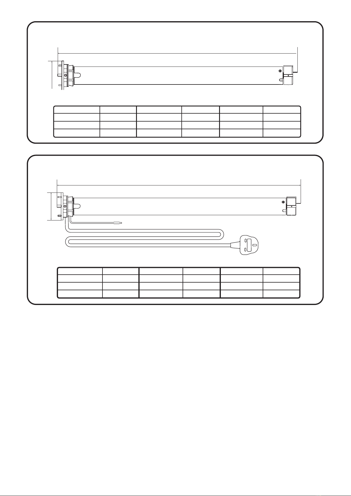
1a. ROLLER MOTORS
504mm
40mm
ROLLER 38 BATTERY MOTOR 191723
ROLLER 45 BATTERY MOTOR 191713
TECHNICAL SPECIFICATION - ROLLER 38 BATTERY MOTOR 191723
OUTPUT SPEED 40RPM
RATED TORQUE 1.1 N.m
RATED VOLTAGE 12v
RATED POWER 10W
RATED CURRENT0 .83A
IP PROTECTION RATING 44
LIFTING CAPACITY
RUNNING NOISE
TECHNICAL SPECIFICATION
TECHICAL SPECIFICATION
710mm
64mm
TECHNICAL SPECIFICATION - ROLLER 55 BATTERY MOTOR 191711
OUTPUT SPEED 28RPM
RATED TORQUE 2N.m
RATED VOLTAGE 12v
RATED POWER 14W
RATED CURRENT1 .16A
IP PROTECTION RATING 44
LIFTING CAPACITY
RUNNING NOISE
TECHNICAL SPECIFICATION
ROLLER 45 MAINS MOTOR 191714
TECHNICAL SPECIFICATION
OUTPUT SPEED 28RPM
RATED TORQUE 2N.m
RATED VOLTAGE 12v
RATED POWER 14W
RATED CURRENT1 .16A
IP PROTECTION RATING 44
LIFTING CAPACITY
RUNNING NOISE
710mm
mm46
700mm
CONTROL TYPE
LIMITS
OUTPUT SPEED
RATED TORQUE
RATED VOLTAGE
RATED POWER
RATED CURRENT
RADIO FREQUENCY
IP RATING
LIFTING CAPACITY
MIN. BLIND WIDTH
MOTOR LENGHT
RADIO
ELECTRONIC
(set remotely)
40 rmp
12 V
10 W
0.83 A
1.1 N.m 433.92 MHz
IP44
5.8 Kg
510 mm
590 mm
CONTROL TYPE
LIMITS
OUTPUT SPEED
RATED TORQUE
RATED VOLTAGE
RATED POWER
RATED CURRENT
RADIO FREQUENCY
IP RATING
LIFTING CAPACITY
MIN. BLIND WIDTH
MOTOR LENGHT
RADIO
ELECTRONIC
(set remotely)
28 rmp
12 V
18 W
1.5 A
3 N.m 433.92 MHz
IP44
13.3 Kg
700 mm
770 mm
CONTROL TYPE
LIMITS
OUTPUT SPEED
RATED TORQUE
RATED VOLTAGE
RATED POWER
RATED CURRENT
RADIO FREQUENCY
IP RATING
LIFTING CAPACITY
MIN. BLIND WIDTH
MOTOR LENGHT
RADIO
ELECTRONIC
(set remotely)
20 rmp
230 V
121 W
0.53 A
6 N.m 433.92 MHz
IP44
26.7 Kg
570 mm
640 mm
510mm
570mm
CONTROL TYPE
LIMITS
OUTPUT SPEED
RATED TORQUE
RATED VOLTAGE
RATED POWER
RATED CURRENT
RADIO FREQUENCY
IP RATING
LIFTING CAPACITY
MIN. BLIND WIDTH
MOTOR LENGHT
RADIO
ELECTRONIC
(set remotely)
20 rmp
230 V
121 W
0.53 A
6 N.m 433.92 MHz
IP44
26.7 Kg
570 mm
640 mm
CONTROL TYPE
LIMITS
OUTPUT SPEED
RATED TORQUE
RATED VOLTAGE
RATED POWER
RATED CURRENT
RADIO FREQUENCY
IP RATING
LIFTING CAPACITY
MIN. BLIND WIDTH
MOTOR LENGHT
RADIO
ELECTRONIC
(set remotely)
28 rmp
12 V
18 W
1.5 A
3 N.m 433.92 MHz
IP44
13.3 Kg
700 mm
770 mm
CONTROL TYPE
LIMITS
OUTPUT SPEED
RATED TORQUE
RATED VOLTAGE
RATED POWER
RATED CURRENT
RADIO FREQUENCY
IP RATING
LIFTING CAPACITY
MIN. BLIND WIDTH
MOTOR LENGHT
RADIO
ELECTRONIC
(set remotely)
40 rmp
12 V
10 W
0.83 A
1.1 N.m 433.92 MHz
IP44
5.8 Kg
510 mm
590 mm
MOTOR LENGTH
MOTOR LENGTH
MOTOR LENGTH
7
ROLLER 55 MAINS MOTOR 191712
ROLLER 55 BATTERY MOTOR 191711
TECHNICAL SPECIFICATION
TECHNICAL SPECIFICATION
710mm
mm46
OUTPUT SPEED 28RPM
RATED TORQUE 3N.m
RATED VOLTAGE 12v
RATED POWER 26W
RATED CURRENT2 .20A
IP PROTECTION RATING 44
LIFTING CAPACITY
RUNNING NOISE
838mm
mm
4
6
OUTPUT SPEED 28RPM
RATED TORQUE 2N.m
RATED VOLTAGE 12v
RATED POWER 14W
RATED CURRENT1 .16A
IP PROTECTION RATING 44
LIFTING CAPACITY
RUNNING NOISE
CONTROL TYPE
LIMITS
OUTPUT SPEED
RATED TORQUE
RATED VOLTAGE
RATED POWER
RATED CURRENT
RADIO FREQUENCY
IP RATING
LIFTING CAPACITY
MIN. BLIND WIDTH
MOTOR LENGHT
RADIO
ELECTRONIC
(set remotely)
28 rmp
12 V
26 W
1.5 A
3 N.m 433.92 MHz
IP44
10.9 Kg
760 mm
890 mm
CONTROL TYPE
LIMITS
OUTPUT SPEED
RATED TORQUE
RATED VOLTAGE
RATED POWER
RATED CURRENT
RADIO FREQUENCY
IP RATING
LIFTING CAPACITY
MIN. BLIND WIDTH
MOTOR LENGHT
RADIO
ELECTRONIC
(set remotely)
28 rmp
230 V
155 W
0.63 A
6 N.m 433.92 MHz
IP44
21.8 Kg
760 mm
830 mm
760mm
760mm
CONTROL TYPE
LIMITS
OUTPUT SPEED
RATED TORQUE
RATED VOLTAGE
RATED POWER
RATED CURRENT
RADIO FREQUENCY
IP RATING
LIFTING CAPACITY
MIN. BLIND WIDTH
MOTOR LENGHT
RADIO
ELECTRONIC
(set remotely)
28 rmp
12 V
26 W
1.5 A
3 N.m 433.92 MHz
IP44
10.9 Kg
760 mm
890 mm
MOTOR LENGTH 830 mm
CONTROL TYPE
LIMITS
OUTPUT SPEED
RATED TORQUE
RATED VOLTAGE
RATED POWER
RATED CURRENT
RADIO FREQUENCY
IP RATING
LIFTING CAPACITY
MIN. BLIND WIDTH
MOTOR LENGTH
RADIO
ELECTRONIC
(set remotely)
28 rmp
230 V
155 W
0.63 A
6 N.m 433.92 MHz
IP44
21.8 Kg
780 mm
830 mm
FUNCTIONAL FEATURES
• Bi-Directional Functionality
• Electronic Limit Setting
• Jog Mode
• Program / Operation Button (P1)
• Three Speed Settings (battery motors)
• Built-in Lithium-ion Battery (battery motors)
• Mains / Solar Charging (battery motors)
• Switch Direction
• Built-in Radio Receiver
• Favourite Stop Position
• Internally Stored Settings
• Pair with up to 10 Control Devices
8
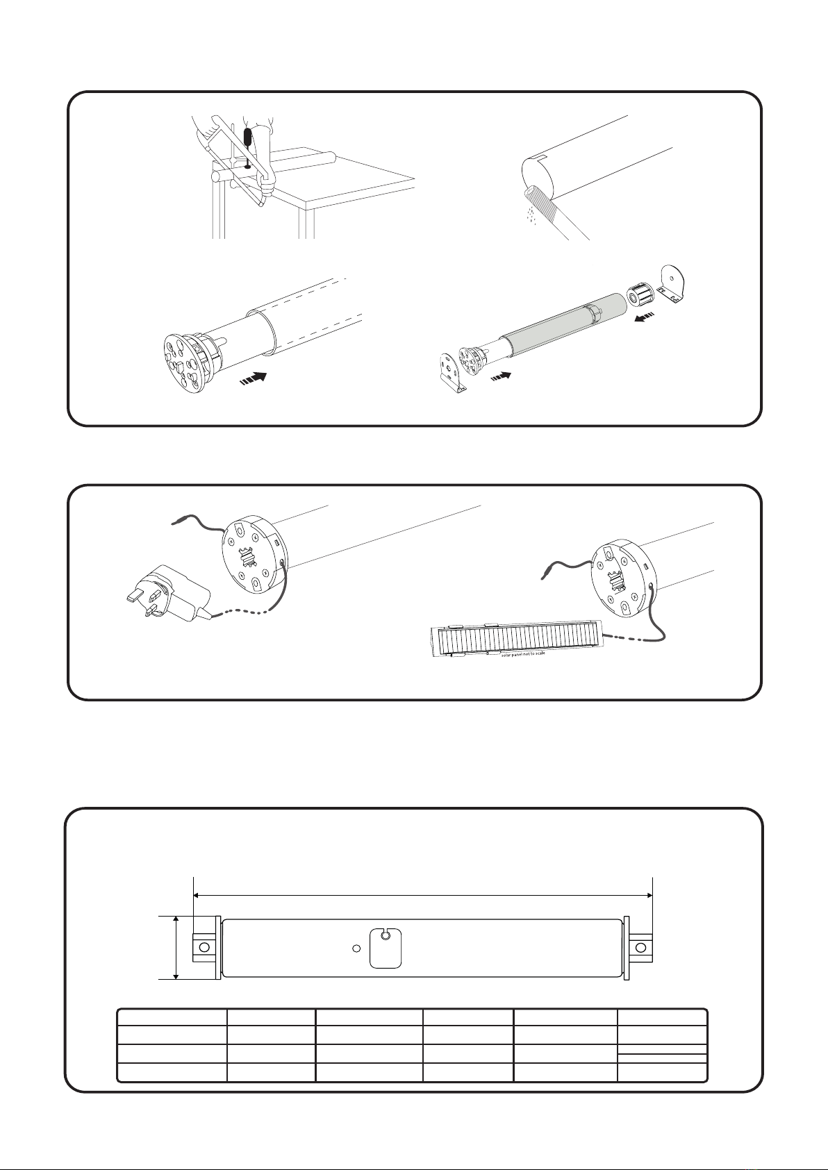
INSTALLATION
1 2
3 4
CHARGING
APPLICABLE FOR BATTERY MOTORS ONLY
The Dream Motors have a built-in battery that utillises
a mains charger 191692 or solar panel 191682 to recharge.
1b. ROMAN/PLEATED MOTORS
ROMAN BLIND LV BATTERY MOTOR 191695
PLEATED BLIND LV BATTERY MOTOR 191699
TECHNICAL SPECIFICATION
205mm
mm82
OUTPUT SPEED 34RPM
RATED TORQUE 0.8 N.m
RATED VOLTAGE 12v
RATED POWER 12W
RATED CURRENT1 .03A
IP PROTECTION RATING 20
LIFTING CAPACITY
RUNNING NOISE
CONTROL TYPE
LIMITS
OUTPUT SPEED
RATED TORQUE
RATED VOLTAGE
RATED POWER
RATED CURRENT
RADIO FREQUENCY
IP RATING
LIFTING CAPACITY
MIN. BLIND WIDTH
MOTOR LENGHT
RADIO
ELECTRONIC
(set remotely)
34 rmp
12 V
12 W
0.3 A
0.82 N.m 433.92 MHz
IP1.9
8 Kg
205 mm
PLEATED 450 mm
ROMAN 500 mm
FUNCTIONAL FEATURES
• Bi-Directional Functionality
• Electronic Limit Setting
• Jog Mode
• Program / Operation Button (P1)
• Three Speed Settings
• External Li-ion Battery attached by a wire
• Mains / Solar battery charging
• Mains power option with a power adapter
• Built-in Radio Receiver
• Favourite Stop Position
• Internally Stored Settings
• Pair with up to 10 Control Devices
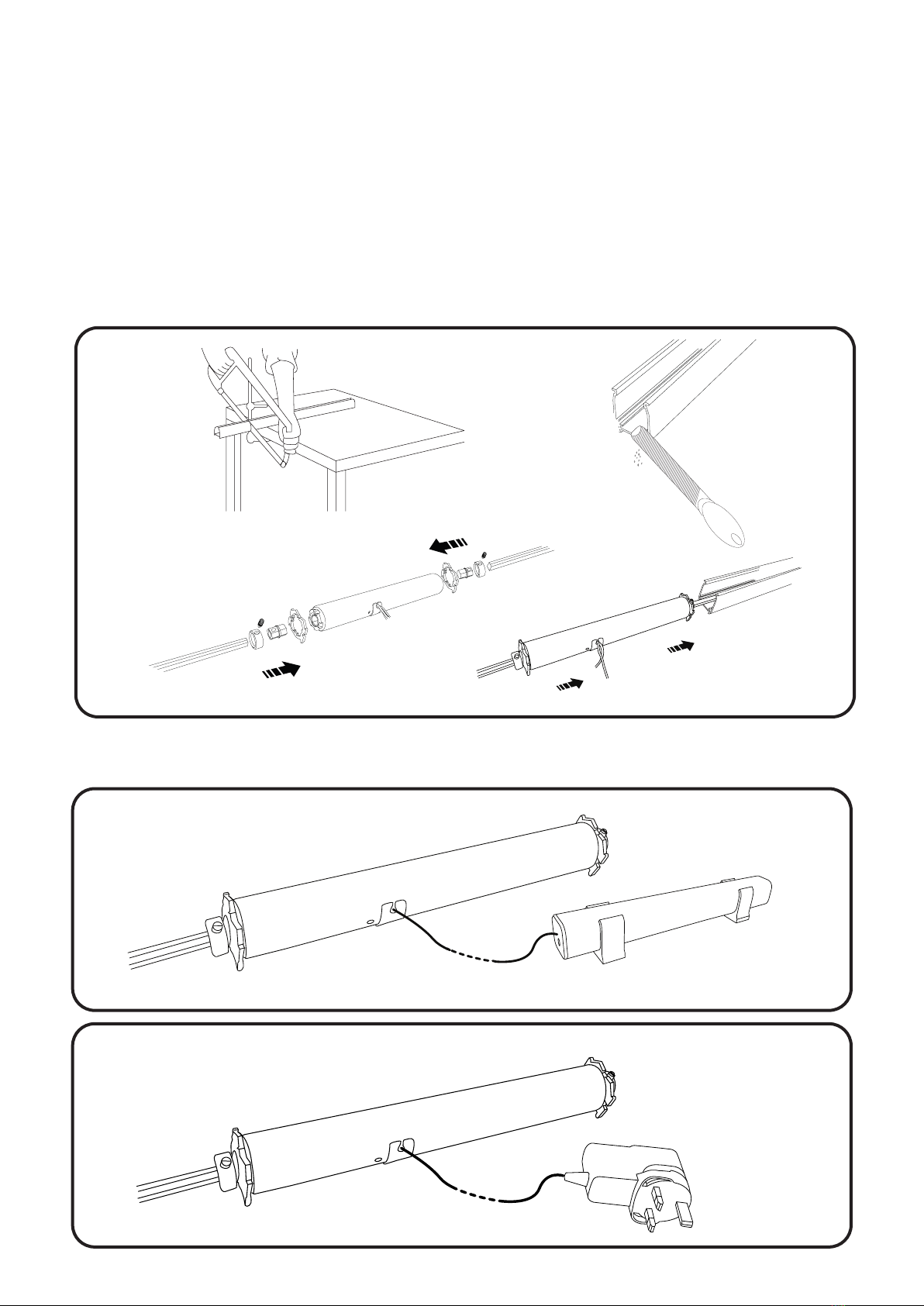
2b. INSTALLATION
INSTALLATION
1 2
3 4
POWER SOURCE
BATTERY
MAINS - POWER ADAPTER
Li-ion Rechargeable Battery 191720
Power Adapter 191702
Plug Roman/Pleated blind motor
directly into a mains socket
Power Roman/Pleated blind motor
with no visible power cables
9

10
CHARGING
Li-ion rechargeable battery utillises a mains charger 191692 or solar panel 191682 to recharge.
The remote is compatible with all bi-directional Dream Motors and older uni-directional motors.
For programming and paring options go to page 10.
For programming the additional wall switch’s features go to page 17.
TECHINCAL SPECIFICATION
DISPLAY SCREEN
UP
STOP
DOWN
CHANNEL SELECTOR
P2
SETTING
BUTTONS
BATTERY
44
11
130
INPUT VOLTAGE 3V
BATTERY CR2450
TRANSMITTING FREQUENCY 433.925MHz
TRANSMITTING POWER 10MW
OUTSIDE TRANSMISSION RANGE 200m
INSIDE TREANSMISSION RANGE 35m
2a. DREAM 15-CHANNEL REMOTE 191679
2.DREAM CONTROLS
5515
11
The wall switch is compatible with all bi-directional Dream Motors and older uni-directional motors.
The programming and paring proccess is exactly the same as for the remote. For programming and
paring options go to page 10.
For programming the additional wall switch’s features go to page 17.
TECHINCAL SPECIFICATION
FUNCTIONAL FEATURES
FUNCTIONAL FEATURES
• Bi-directional functionality
• Uni-directional functionality
• 15 channels
• Pair up to 20 motors per channel
• Button lock/unlock option
• Hide/Unhide channel option
• Standard CR2450 cell battery
• Magnetic wall bracket
• Bi-directional functionality
• Uni-directional functionality
• 15 channels
• Pair up to 20 motors per channel
• Button lock/unlock option
• Hide/Unhide channel option
• Standard CR2450 cell battery
• Magnetic wall bracket
Channel ‘0’ to operate all paired
blinds simultaneously
80mm
Channel selector - UP
UP
STOP
DOWN
Channel selector - DOWN
P2 Setting button
Battery
Display screen
Channel ‘0’ button
80mm
INPUT VOLTAGE 3V
BATTERY CR2450
TRANSMITTING FREQUENCY 433.925MHz
TRANSMITTING POWER 10MW
OUTSIDE TRANSMISSION RANGE 200m
INSIDE TREANSMISSION RANGE 35m
2b. DREAM 15-CHANNEL WALL SWITCH 191685
• Bi-directional functionality
• Uni-directional functionality
• 15 channels
• Battery replacing tool
• Button lock/unlock option
• Hide/Unhide channel option
• Standard CR2450 cell battery
• Magnetic wall bracket
12
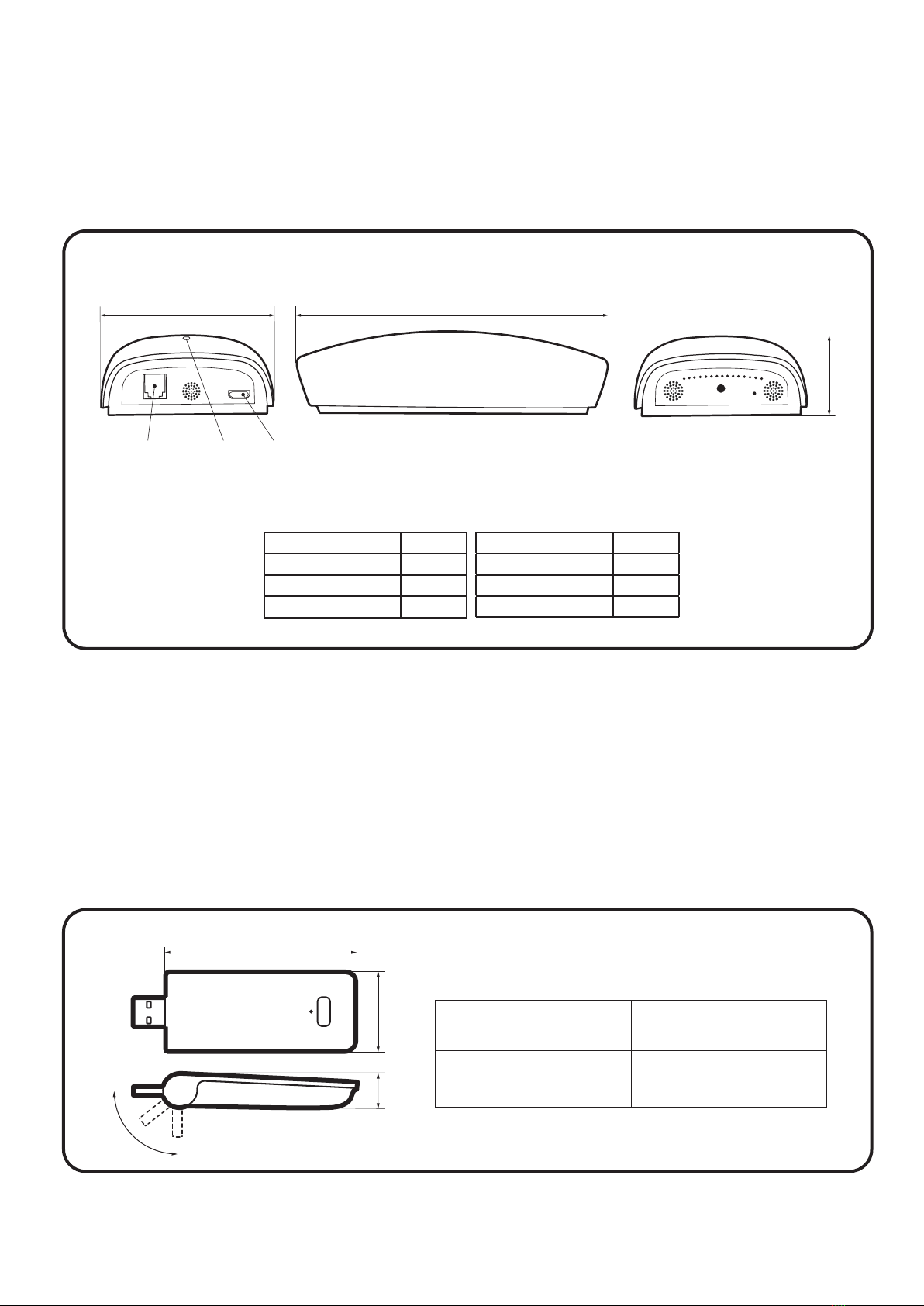
2c. DREAM HUB-PRO 191726
2d. DREAM HUB-MINI 191717
The Dream Hub works with all Dream Motors, by connecting them to your Wi-Fi network to allow you
to operate your blinds via smartphone with the free Connector app or voice control devices.
For Connector App download instructions go to page 18.
The Dream Hub-Mini is a smaller version of its Pro equivalent and likewise works with all Dream Mo-
tors, by connecting them to your Wi-Fi network to allow you to operate your blinds via smartphone
with the free Connector app or voice control devices.
For Connector App download instructions go to page 18.
72mm 132mm
32mm
USB Port
LED light
RJ9 Port
INPUT VOLTAGE3 V
BATTERYC R2450
TRANSMITTING FREQUENCY 433.925MHz
TRANSMITTING POWER 10MW
OUTSIDE TRANSMISSION RANGE 200m
INSIDE TREANSMISSION RANGE 35m
OPERATING TEMPERATURE- 5C ~ 50C
TECHNICAL SPECIFICATION
TECHNICAL SPECIFICATION
TECHICAL SPECIFICATION
84mm
84mm13mm
PRODUCT SPECIFICATION
CONNECTIVITY:
Wi-Fi: 2.4GHz (802.11b/g/n)
RADIO FREQUENCY:
433.92 MHz
WORKING TEMPERATURE:
0OC - 40OC
POWER INPUT:
DC 5V/1A (USB Type-A)

13
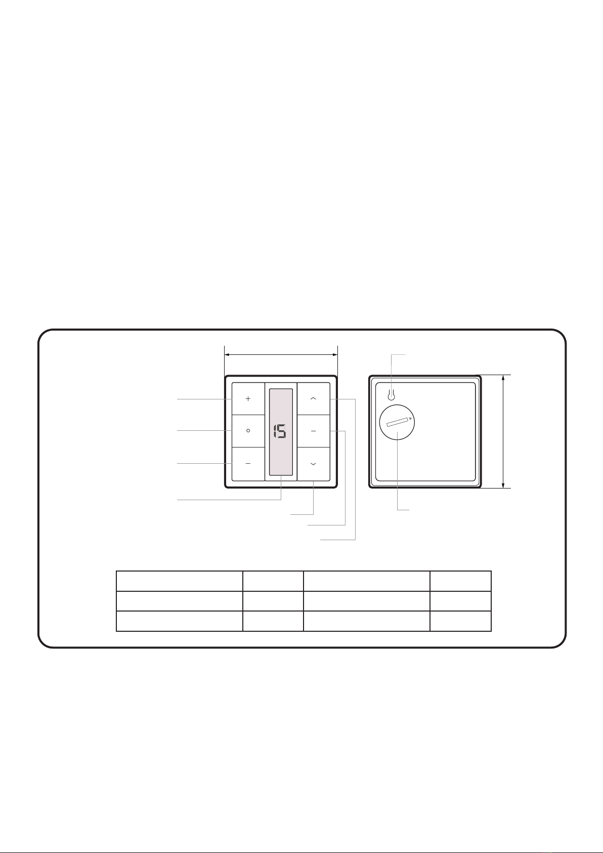
2f. SUN SENSOR 191727
2e. DREAM SIGNAL BOOSTER 191716
The Sun Sensor is compatible with all Dream Motors and works on a simple premise: automatically
closing blinds when the sun is too bright and opening them as soon as the situation changes.
For programming and pairing instructions go to page 19.
The Dream Signal Booster works with all Dream Motors and control devices. When plugged in between
a control device and blinds extends the signal range up to 200m.
For set up instructions go to page 18.
0
1
2
3
4
42mm
Light level indicators
Sun Button:
-press - indicates the light level and modes
-press & hold - switches between modes
UP Button:
moves blind upwards
P2 Button:
pairs the sensor with blind
Sensor
Suction pad slot
• Input voltage: 3V
• Transmitting frequency: 433.925MHz
• Transmitting power: 10 milliwatt
• Light intensity range: 15 ~ 75kilolux
• Operating temperature: -20c - 60c
TECHICAL SPECIFICATION
FUNCTIONAL FEATURES
• Small form for descreet positioning
• Battery included
• Operates in temperatures -20º to 60º
• Low battery alert
• Two fixing options
• Four lux thresholds
• Three modes
• Easy pairing with Dream Motors
64mm
11mm 23mm
TECHNICAL SPECIFICATION
POWER INPUT:DC 4.8V - 5.2V OPERATING TEMPERATURE: -5
O
C - 50
O
C
WORKING CURRENT:<20mA
TRANSMITION DISTANCE: up to 200m
TRANSMITING FREQUENCY:433.925MHz
TRANSMITING POWER: 10mW
INPUT VOLTAGE
TRANSMITTING DISTANCE
RADIO FREQUENCY
LIGHT RANGE
WORKING TEMPERATURE
3 V
UP TO 30 m -20OC - 60OC
10 mW
433.925 MHz
TRANSMITTING POWER 15 - 75 Kilolux
TECHICAL SPECIFICATION

PROGRAMMING
INSTRUCTIONS
14
PROGRAMMING INSTRUCTIONS
1. DREAM MOTORS/MULTI-CHANNEL REMOTE CONTROL
Every motor in our Dream range is equipped with bi-directional technology that only a� ords them
some very clever functionality when they’re coupled with smart devices, but also makes set up and
operation with our Dream Multi-Channel Handheld Remote Control a quick and easy process.
These instructions apply to all bi-directional Dream motors – including all roller, pleated and roman
motors – battery or mains powered.
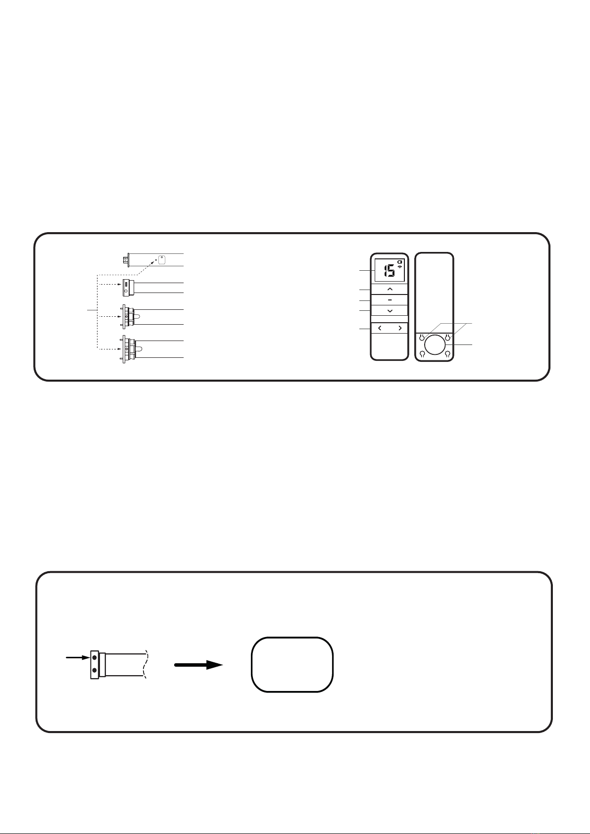
1a. BUTTON SPECIFICATION
1b. P1 BUTTON SETTINGS
DISPLAY SCREEN
UP
STOP
DOWN
CHANNEL SELECTOR P2 SETTING BUTTONS
BATTERY
P1 BUTTON
ROMAN/PLEATED LV BATTERY MOTOR
ROLLER BLIND 38 BATTERY/MAINS MOTOR
ROLLER BLIND 45 BATTERY/MAINS MOTOR
ROLLER BLIND 55 BATTERY/MAINS MOTOR
The Dream motors come in a few shapes and sizes but the set up and control instructions are identical
for all of them. Crucial to these instructions is the P1 button that can be found on every motor.
The button in recessed into the motor to avoid accidental activation but is easily accessed with a pen
or a similar device.
As well as being utilised in the pairing process, the P1 button can be used to control the blind when an
external control device is unavailable as well as functions such as restoring factory settings.
Press P1
for 1sec
UP / DOWN
/ STOP
Note:
When in jog-mode, holding the up
or down buttons will temproralily provide
continous-moving.
SHORT PRESS FUNCTION
15
PROGRAMMING INSTRUCTIONS
1. DREAM MOTORS/MULTI-CHANNEL REMOTE CONTROL
Every motor in our Dream range is equipped with bi-directional technology that only a� ords them
some very clever functionality when they’re coupled with smart devices, but also makes set up and
operation with our Dream Multi-Channel Handheld Remote Control a quick and easy process.
These instructions apply to all bi-directional Dream motors – including all roller, pleated and roman
motors – battery or mains powered.
1a. BUTTON SPECIFICATION
1b. P1 BUTTON SETTINGS
DISPLAY SCREEN
UP
STOP
DOWN
CHANNEL SELECTOR P2 SETTING BUTTONS
BATTERY
P1 BUTTON
ROMAN/PLEATED LV BATTERY MOTOR
ROLLER BLIND 38 BATTERY/MAINS MOTOR
ROLLER BLIND 45 BATTERY/MAINS MOTOR
ROLLER BLIND 55 BATTERY/MAINS MOTOR
The Dream motors come in a few shapes and sizes but the set up and control instructions are identical
for all of them. Crucial to these instructions is the P1 button that can be found on every motor.
The button in recessed into the motor to avoid accidental activation but is easily accessed with a pen
or a similar device.
As well as being utilised in the pairing process, the P1 button can be used to control the blind when an
external control device is unavailable as well as functions such as restoring factory settings.
Press P1
for 1sec
UP / DOWN
/ STOP
Note:
When in jog-mode, holding the up
or down buttons will temproralily provide
continous-moving.
SHORT PRESS FUNCTION
16
Hold P1
for 6sec
Motor
jogs x2 Beeps x2
SLEEP
MODE
Release
P1
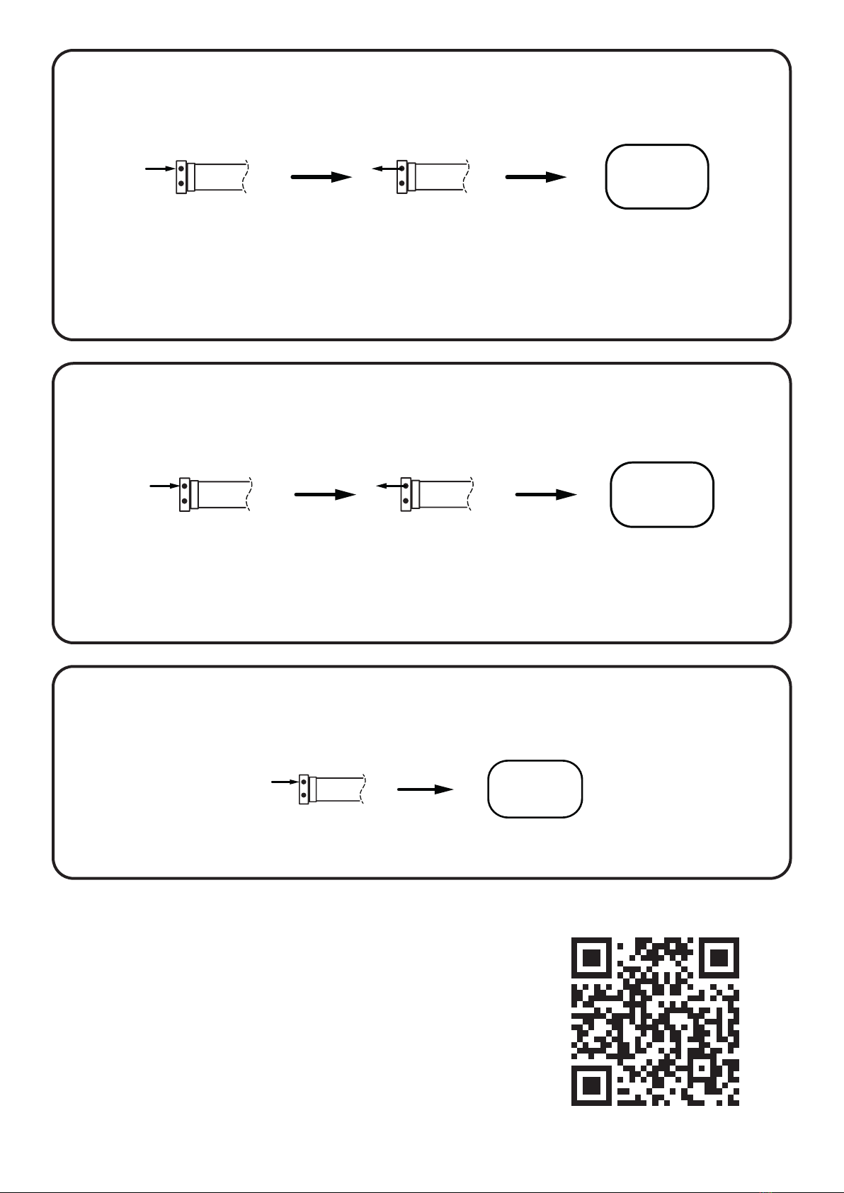
SLEEP MODE
SWITCHING DIRECTION
RESTORING FACTORY SETTINGS
Note:
Sleep mode can be utilised to temporariliy deactivate a motors’s radio functionality, allowing
for multiple motors to be added to a shared channel without disruption. Press P1 to restore
functionality.
Hold P1
for 10sec
Motor
jogs x3
Release P1
Beeps x3
DIRECTION
SWITCHED
Note:
Switching direction using the P1 button is only available once a remote has been paired
with the motor.
Hold P1
for 14sec
Motor jogs x4
Beeps x4
FACTORY
SETTINGS
RESTORED
Visit our YouTube channel for video equivalent
of these instructions.
DREAM RANGE PROGRAMMING INSTRUCTIONS
- OVERVIEW AND P1 FUNCTIONALITY

Hold P1
for 6sec
Motor
jogs x2 Beeps x2
SLEEP
MODE
Release
P1
SLEEP MODE
SWITCHING DIRECTION
RESTORING FACTORY SETTINGS
Note:
Sleep mode can be utilised to temporariliy deactivate a motors’s radio functionality, allowing
for multiple motors to be added to a shared channel without disruption. Press P1 to restore
functionality.
Hold P1
for 10sec
Motor
jogs x3
Release P1
Beeps x3
DIRECTION
SWITCHED
Note:
Switching direction using the P1 button is only available once a remote has been paired
with the motor.
Hold P1
for 14sec
Motor jogs x4
Beeps x4
FACTORY
SETTINGS
RESTORED
Visit our YouTube channel for video equivalent
of these instructions.
DREAM RANGE PROGRAMMING INSTRUCTIONS
- OVERVIEW AND P1 FUNCTIONALITY
17
1c. PAIRING A REMOTE AND INITIAL SETTINGS
Before starting the process of pairing a handheld remote to a Dream motor, choose the channel to
which it is to be paired.
Channel Zero is reserved for simultaneously controlling all blinds paired to a remote and cannot be
used for pairing, programming or other adjustments
If using a battery powered motor, ensure that it is su ciently charged to complete the set-up process.
Charging a motor from empty will take approximately 6 hours.
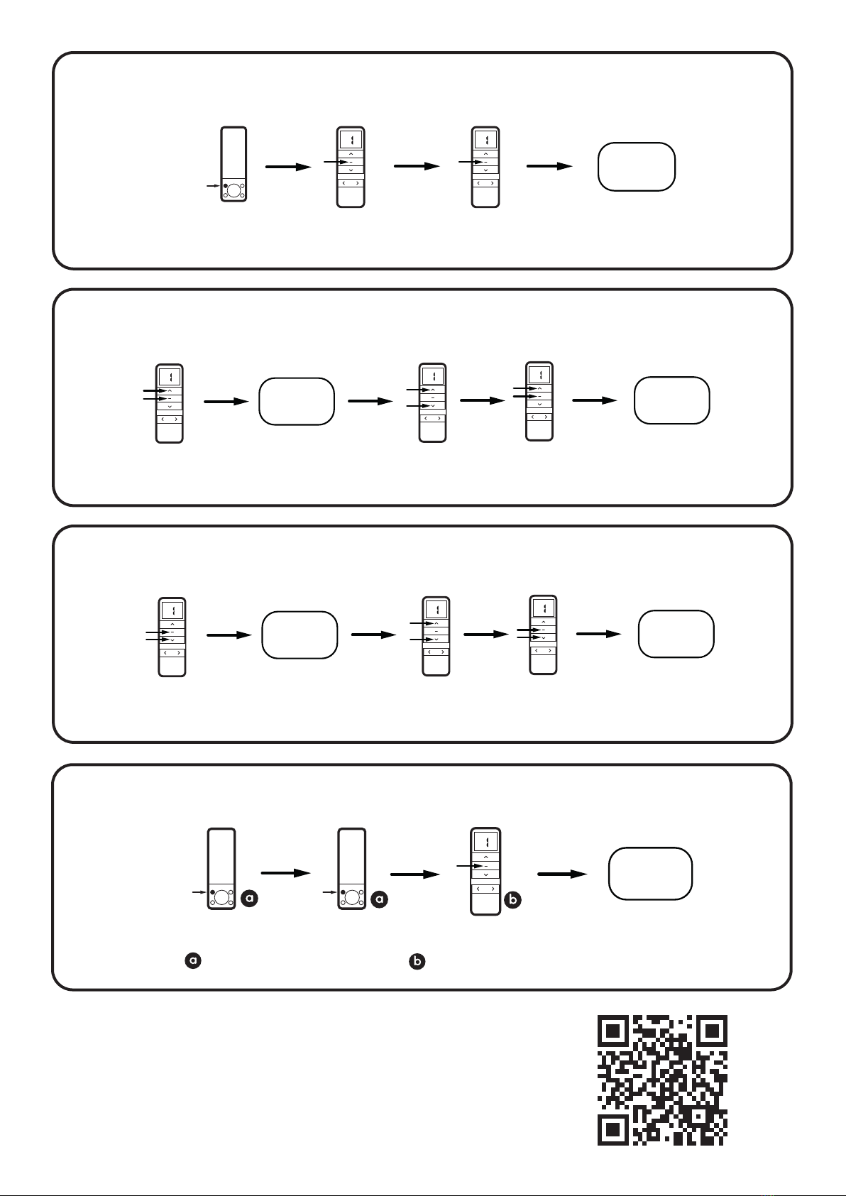
PAIRING A REMOTE WITH A MOTOR
REMOVING A MOTOR FROM A REMOTE
SWITCHING DIRECTION
Motor
jogs x1 Motor
beeps x1
Motor
jogs x2
beeps x3
Release
P1 Press for 2sec
within 10s
PAIRING
COMPLETE
Press P1
for 2sec
Motor
jogs x1 Motor
beeps x1
Motor
jogs x2
beeps x3
Release
P1 Press for 2sec
within 10s
MOTOR
REMOVED
Press P1
for 2sec
Select a motor
to remove
Note:
After pairing a remote and before setting limits, the motor will be defaulted to jog-mode. To
switch to continuous-mode, see ADVANCED FUNCTIONALITY - SWITCHING BETWEEN JOG
MODE AND CONTINUOUS MODE on page 15.
Note:
Switching direction with a remote device is only possible before setting top and bottom limits.
To switch after limits have been set, see P1 BUTTON SETTINGS - SWITCHING DIRECTION
on page 14.
Press together
for 2sec
DIRECTION
SWITCHED
Motor
jogs x1

18
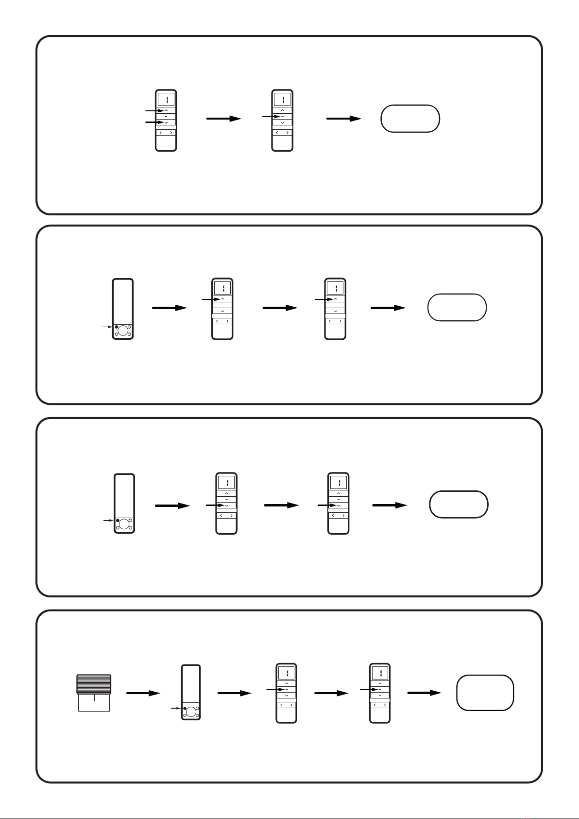
SETTING THE BOTTOM LIMIT
SWITCHING FROM CONTINUOUS MODE TO JOG MODE
Run blind to
bottom
position
BOT TOM
LIMIT SET
Motor jogs x2
Beeps x3
Press together
for 2sec
Note:
After setting top and bottom limits, the motor will automatically switch to continuous mode.
To switch to jog mode, see ADVANCED FUNCTIONALITY - SWITCHING BETWEEN JOG MODE
AND CONTINUOUS MODE on page 15.
Note:
When in jog mode, holding the up or down buttons will provide continuous-moving temporarily.
1d. ADVANCED SETTINGS
Visit our YouTube channel for video equivalent
of these instructions.
DREAM RANGE PROGRAMMING INSTRUCTIONS
- PAIRING A REMOTE AND INITIAL SETTINGS
Hold together
for 5sec
Press for
1sec
Motor
jogs x1 Motor jogs x1
Beeps x1
JOG
MODE
SETTING THE TOP LIMIT
Run blind to
top position
Press together
for 2sec
TOP
LIMIT SET
Motor jogs x2
Beeps x3
19
SWITCHING FROM JOG MODE TO CONTINUOUS MODE
INCREASING MOTOR SPEED
BATTERY MOTORS ONLY
DECREASING MOTOR SPEED
BATTERY MOTORS ONLY
SETTING A FAVOURITE STOP POSITION
Hold together
for 5sec
Press for
1sec
Motor
jogs x1 Motor jogs x2
Beeps x3
CONTINUOUS
MODE
Note:
When in jog mode, holding the up or down buttons will provide continuous-moving temporarily.
Note:
If the motor does not response to these instructions, it has already reached its upper speed setting.
Note:
If the motor does not response to these instructions, it has already reached its upper speed setting.
Note:
Once the favourite stop position has been set, it can be activated by holding the stop button for 2 seconds.
Press for
1sec
Motor jogs x2
Beeps x1
SPEED
INCREASED
Press P2
for 1sec
Press for
1sec
Motor jogs x1
Beeps x1
Motor jogs x1
Beeps x1
Motor jogs x2
Beeps x1
SPEED
DECREASED
Press P2
for 1sec
Press for
1sec
Motor jogs x1
Beeps x1
Press for
1sec
Motor jogs x1
Beeps x1
Run shade to
desired position Press P2
for 1sec
Press
for 1sec
FAVOURITE
POSITION
SET
Motor jogs x1
Beeps x1 Motor jogs x1
Beeps x1
Press
for 1sec
Motor jogs x2
Beeps x3
20
FINE-TUNING A TOP LIMIT
CLEARING A FAVOURITE STOP POSITION
FINE-TUNING A BOTTOM LIMIT
ADDING/REMOVING AN EXTRA REMOTE
Hold together
for 5sec
Hold together
for 2sec
Jog to desired
position
FINE-TUNE
MODE
ENGAGED
TOP
LIMIT SET
Motor jogs x1
Beeps x1 Motor jogs x2
Beeps x3
Hold together
for 5sec
Hold together
for 2sec
Jog to desired
position
FINE-TUNE
MODE
ENGAGED
BOT TOM
LIMIT SET
Motor jogs x1
Beeps x1 Motor jogs x2
Beeps x3
REMOTE
PAIRED
Hold
for 2sec
Press P2
for 1sec Press P2
for 1sec
Motor jogs x1
Beeps x1 Motor jogs x1
Beeps x1 Motor jogs x2
Beeps x3
Existing remote control device Remote control device to add/remove
Press
for 1sec
Press
for 1sec
FAVOURITE
CLEARED
Press P2
for 1sec
Motor jogs x1
Beeps x1 Motor jogs x1
Beeps x1
Motor jogs x1
Beeps x1
Visit our YouTube channel for video equivalent
of these instructions.
DREAM RANGE PROGRAMMING INSTRUCTIONS
- ADVANCED FUNCTIONALITY
Other manuals for Dream Range
1
Table of contents
Other DecorQuip Remote Control manuals

Popular Remote Control manuals by other brands


RCA
RCA RCR311BIR owner's manual

Raymarine
Raymarine RMK-9 Installation and operation instructions

Mitsubishi Electric
Mitsubishi Electric MRCH1 operating manual

GRAUPNER
GRAUPNER HoTT 2.4 VARIO Module 33601 manual

Acoustic Research
Acoustic Research Xsight Touch owner's manual

LUZ NEGRA
LUZ NEGRA 41.089 manual


