decrane aerospace LCD-9121-101 SERIES User manual

7300 Industry Drive, North Little Rock, AR 72117
Phone: 501-955-2929 Fax: 501-955-2988
www.decraneaerospace.com
Installation Manual
LCD-9121-101-x
12.1" LCD Monitor
Document # 540365

DeCrane Aerospace Audio International, Inc. LCD-9121-101-x Installation Manual
Document # 540365, Rev IR, 03/2008 Page 1 of 18
Document Revision History
Rev. Level Date Description
IR 03/2008 Initial Release
Reference Documents
(or latest revision)
Document # Description
526090 LCD-9121-101-x Outline Drawing
525667 SP-LCD6 Assembly Drawing
Service Bulletin List
Service
Bulletin # Subject Manual
Revision
Revision
Date
Table of Illustrations
Section # Description Page #
2.3 Typical Application 4
6.0 Reference Drawings 16-18
PROPRIETARY NOTICE: Despite any other copyright notice, this document and information
disclosed herein contains confidential, proprietary designs owned by DeCrane Aerospace Audio
International. Neither this document nor the data contained herein shall be
reproduced, used, or
disclosed to anyone without the written authorization of DeCrane Aerospace Audio International.

DeCrane Aerospace Audio International, Inc. LCD-9121-101-x Installation Manual
Document # 540365, Rev IR, 03/2008 Page 2 of 18
Table of Contents
Section Description Page
1.0 General Information ……………………………………………. 3
1.1 Introduction ……………………………………………………….. 3
1.2 Purpose of the Equipment ………………………………………. 3
1.3 Optional Equipment ……………. .………………………………. 3
2.0 Application ………………………………………………………..
3
2.1 Introduction ……………………………………………………….. 3
2.2 Communication ………………………………………………....... 4
2.3 Block Diagram - Typical Application …………………………….
4
2.4 Typical Interfaces ………………………………………………… 4
3.0 Installation ……………………………………………………….. 5
3.1 Prior to Installation ……………………………………………….. 5
3.2 Unpacking and Inspection ………………………………………. 6
3.3 Cautions & Warnings ……………………………………………..
6
3.4 Wiring Requirements …………………………………………….. 7
3.5 Physical Characteristics …………………………………………. 8
3.6 Clearance & Separation …………………………………………. 8
3.7 Electrical Characteristics………………………………………….
9
3.8 Mating Connector Information ……………..…………………….
11
3.9 Pinout Assignment Descriptions ………………………………...
11
3.10
SP-LCD6 Configuration Overview………………………………. 13
4.0 Instructions for Continued Airworthiness ……..………….. 13
4.1 Airworthiness Limitations………………..……………………..… 13
4.2 Cleaning Method………………………………………………….. 14
4.3 General Troubleshooting Procedures …………………………..
14
4.4 Troubleshooting Chart………………………………………….. 15
5.0 Specifications …………………………………………………… 15
5.1 Unit Specifications-LCD-9121-101-x..………………………….. 15
5.2 Unit Specifications-SP-LCD6……………………………………. 15
6.0 Reference Drawings ……………………………………………. 16
6.1 LCD-9121-101-x………………………………………………….. 16
6.2 SP-LCD6…………….. …………………………………………… 18

DeCrane Aerospace Audio International, Inc. LCD-9121-101-x Installation Manual
Document # 540365, Rev IR, 03/2008 Page 3 of 18
LCD-9121-101-x
12.1" LCD Monitor
1.0 General Information
1.1 Introduction
This manual contains information for the proper installation of the
DeCrane Aerospace Audio International (DAAI) 12.1LCD Monitor, Model
No: LCD-9121-101-x. The “-x” suffix designates the type of connector
utilized; “-1” = Positronic and “-2” = D-Subminiature. Also included are
physical and electrical characteristics of the unit.
1.2 Purpose of the Equipment
DeCrane Aerospace Audio International’s LCD-9121-101-x is a bulkhead
mounted, liquid crystal color active matrix display flat panel LCD monitor
with Composite NTSC/PAL/SECAM video, PC Graphic capabilities, and
Serial Digital Interface (SDI) capabilities. It has a high resolution (800 x
600 SVGA) display capable of displaying full color graphics and video.
The monitor casing is specially designed for EMI and noise-filtering,
guaranteeing a reduction in interference to ensure a high-quality display.
1.3 Optional Equipment
DeCrane Aerospace Audio International offers a comprehensive family of
Cabin Control Modules and Source Equipment, such as DVD players,
integrated touch screens, speakers, and other equipment that will perfectly
complement the LCD-9121-101-x and will be valuable and attractive
additions to any cabin interior. These modules provide convenient
solutions for a variety of frequently encountered interfacing needs or
special requirements and are an important part of DAAI’s “building block”
system for configuring total cabin management.
2.0 Application
2.1 Introduction
If a Composite Video, PC Graphics, or Serial Digital signal is applied to
the LCD-9121-101-x’s respective inputs, then the monitor will display that
format. In the case that both Composite and VGA are applied, the monitor
defaults to the VGA input. The user can switch between inputs, or set
video input priority, using the On Screen Display.

DeCrane Aerospace Audio International, Inc. LCD-9121-101-x Installation Manual
Document # 540365, Rev IR, 03/2008 Page 4 of 18
2.2 Communication
This unit incorporates an RS-485 serial data bus interface for
communication purposes to other network-connected devices. All RS-485
serial data bus electronic interface parameters are compliant to DAAI
document #640071.
2.3 Block Diagram - Typical Application
2.4 Typical Interfaces
2.4.1 Typical Video Input (Analog) interfaces include various types of
level compliant sources of VGA and composite NTSC/PAL/SECAM.
2.4.2 The digital video input accepts SDI Video as defined by
ANSI/SMPTE 259M-1997digital format.
2.4.3 SP-LCD6 is an external switch utilized for monitor set-up. The
switch, which must be ordered separately, provides configuration
control via DAAI’s proprietary RS-485 digital data bus
communication or may be configured directly to the J2 connector.
Refer to Section 3.10 SP-LCD6 Configuration Overview, for monitor
set up. The SP-LCD6 may be removed and stored after the monitor
is set up or can be mounted near the monitor for frequent use.
CONTROL PANEL
AUDIO VIDEO
CONTROL MODULE
REPEATER
AI-485RP
IR
XMTR/RCVR
IFR-485
DVD
PLAYER
POWER
SWITCHING
MODULE
DVD
PLAYER
VIDEO
VIDEO
AUDIO
AUDIO
RS232 TO RS485
CONVERTER
MSM2912
LCD-9121-101-X
SPEAKER

DeCrane Aerospace Audio International, Inc. LCD-9121-101-x Installation Manual
Document # 540365, Rev IR, 03/2008 Page 5 of 18
Connector J2 provides to the switch panel +28 VDC power and
ground input, serial data bus control, and unit ID strapping pins to
allow programming of multiple units.
2.4.4 Device addressing is accomplished via three (3) ID pins which
allow for a total of eight (8) monitors to be independently addressed
on the data bus.
3.0 Installation
3.1 Prior to installation, the following items should be considered:
3.1.1 During the design and layout of the aircraft cabin, careful
consideration of the location of this module is necessary. Some of
the items to be considered include:
•Space
•Available power supply
•Environmental conditions (temperature, humidity, etc.)
•Length of cable runs
3.1.2 The LCD-9121-101-x shall be installed to conform to the standards
designated by the customer, installing agency, and existing
conditions as to the unit location and type of installation.
3.1.3 If the adjustment switch (SP-LCD6) is to be mounted in the aircraft,
the following should be considered; the pigtail is 24 inches
(60.96 cm) in length ±1 inch (2.54 cm) and has 6-32 x 0.75 inch
mounting studs. Refer to Sections 5.0 and 6.2 for the adjustment
switch characteristics.
3.1.4 A shallow mounting depth makes this monitor ideal for bulkhead
use. The unit has four (4) 8-32 UNF-2B on the left and right sides,
two (2) on each side. In addition, the unit has eight (8) 8-32 UNF-
2B on the top and bottom, four (4) on each side. The minimum
depth should be no less than .30 inches, and the maximum depth
should be no more than .50 inches.
3.1.5 When mounting the unit to the aircraft’s frame, allow sufficient
space for mating connectors.
3.1.6 The maximum length of the connection to PC Graphic (VGA) input
is 15 feet.
3.1.7 This unit is capable of installation/mounting in any orientation
whether horizontal, vertical, inverted, or at an angle.

DeCrane Aerospace Audio International, Inc. LCD-9121-101-x Installation Manual
Document # 540365, Rev IR, 03/2008 Page 6 of 18
3.1.8 Unit chassis ground provided by 8-32 ground lug, see Section 6.0.
Bonding between ground lug and airframe installation to be <1
resistance using <50 impedance cable. No surface prep is
required due to conductive chassis finish.
3.1.9 The monitor should be located as close to the source equipment as
possible in order to reduce the possibility of noise introduced into
the video. Refer to Section 6.0 for unit dimensions.
3.1.10 The LCD-9121-101-x is configured using the external menu
selection switch, SP-LCD6. The switch utilizes a D-Subminiature
connector. This connector mates with the D-Subminiature
connector on the LCD-9121-101-1 model monitor.
3.2 Unpacking and Inspection
3.2.1 Carefully open the packaging and remove the LCD-9121-101-x.
Verify that all components have been included in the package per
the packing list. Inspect the unit for damage. Retain the packing
materials and packing list.
3.2.2 If damage has occurred during shipping, a claim should be filed
with DeCrane Aerospace Audio International WITHIN 24 hours and
a Return Request Authorization Number shall be obtained from
DAAI by contacting the Repair Department at 501.801.8101.
Repackage the unit in its original packaging materials and return it
to DAAI following instructions given by the DAAI representative.
Refer to the front cover of this manual for address. If no return is
necessary, retain the packing list and the packing materials for
storage.
3.3 Cautions and Warnings
3.3.1 It is important to do a pin-to-pin power and ground check on all
connectors. Ensure that power and ground are applied only where
specified. Damage to the unit may result if power or ground is
applied to the wrong points.
3.3.2
3.3.3 DO NOT connect or disconnect the monitor while power is applied.
3.3.4 DO NOT remove any factory-installed screws. Damage to the unit
may result and void any warranties.
3.3.4 DO NOT expose to moisture.

DeCrane Aerospace Audio International, Inc. LCD-9121-101-x Installation Manual
Document # 540365, Rev IR, 03/2008 Page 7 of 18
3.3.5 The SP-LCD6 can be removed and stored after the monitor is set
up or it can be mounted near the monitor for frequent use. Ensure
power is removed from the monitor and/or entertainment system
before connecting or disconnecting the SP-LCD6.
3.3.6 ESD (Electro Static Discharge) guidelines shall be followed.
3.4 Wiring Requirements
3.4.1 Introduction
The installing agency shall supply and fabricate all external cables
and mating connectors. The length and routing of external cables
should be carefully studied and planned before attempting
installation of the equipment. Allow adequate space for installation
of cable and connectors. Avoid sharp bends and placing cables
near aircraft control cables. Maintain a minimum clearance of three
(3) inches from any control cable. If wiring is run parallel to
combustible fluid or oxygen lines, maintain a separation of six (6)
inches between the lines.
3.4.2 Power Wires
The chassis shall be electrically bonded to the airframe structure by
a conductive mounting point with <0.1 resistance using <50
impedance cable. Aluminum wool, nylon webbing impregnated with
aluminum oxide abrasive or fiber bristle brushes are the approved
tools for removing anodized surfaces at mounting point where the
bonding wire is attached. Power and Ground wires shall be in
accordance with M22759 or equivalent. Protect power wires with
circuit breakers or fuses located close to the electrical power
source bus.
3.4.3 Video Lines
Composite Video connections shall be shielded coaxial cable in
accordance with M17/94-RG179 or equivalent. Cable shields shall

DeCrane Aerospace Audio International, Inc. LCD-9121-101-x Installation Manual
Document # 540365, Rev IR, 03/2008 Page 8 of 18
be grounded at the source. Use of individual wires rather than
proper coaxial cable connections through production breaks is
unacceptable, and will cause significant and detrimental noise
introduction to the video signal supplied to the LCD-9121-101-x.
Serial digital video connections are recommended to use shielded
coaxial cable in accordance with PIC V76261 or equivalent.
3.4.4 RS-485 Connections
RS-485 connections shall be 24 AWG (minimum) twisted shielded
cable with the shield properly grounded at the source (the ideal
practice) and floating at the load end. If shield cannot be grounded
at the source, then ground at the load end with the source end
floating. Each wire length shall be terminated at one end only. The
shield for RS-485 shall be terminated to a dedicated pin. Twisted
shielded cable shall be in accordance with NEMA WC 27500 or
equivalent.
3.4.5 Hot-Swapping
This unit is not designed to withstand active power application to
the unit when making all connections to this unit. This unit requires
input power being active prior to making all other connections to the
unit for proper operation.
3.4.6 RGB Connections
RGB wiring shall be in accordance with NEMA WC 27500 or
equivalent.
3.5 Physical Characteristics
3.5.1 Refer to Section 6.0 for unit dimensions.
3.5.2 Chassis material is 5052H32 aluminum with black powder coat
finish. Points to be clear of finish for proper contact to aircraft
frame.
3.6 Clearance and Separation Requirements
When running cables, avoid sharp bends and placing cables near aircraft
control cables. Maintain a MINIMUM clearance of three (3) inches from
any control cable. If wiring is run parallel to combustible fluid or oxygen
lines, maintain a separation of six (6) inches between the lines.

DeCrane Aerospace Audio International, Inc. LCD-9121-101-x Installation Manual
Document # 540365, Rev IR, 03/2008 Page 9 of 18
3.7 Electrical Characteristics
3.7.1 Electrical Specifications for LCD-9121-101-x:
Electrical Nominal Power 750mA @ +28 VDC
Maximum Power 1.25A @ +28 VDC
Operating Voltage
Range +18 to +32 VDC
Screen Size 12.1 (30.73 cm) diagonal
Screen Resolution
(H x V) 800 x 600 (SVGA)
Luminance 250 cd/m²
Color Depth 8-bits, 16,777,216 colors
Viewing Angle 170°Horizontal
170°Vertical
Contrast Ratio 800 Typical
Video Format
Composite
NTSC/PAL/SECAM and
RGB input (PC & SDI
compatible interfaces)
Composite Video Input 1 V
(p-p),
75
Component RGB Input Industry Standard up to
1280 X 1024 (SXGA)
Digital Video Input ANSI/SMPTE 259M-
1997
Operating Temperature +5°to +131°F
-15°to +55°C
Storage Temperature -67°to +185°F
-55°to +85°C
3.7.2 All RS-485 serial data bus electronic interface parameters are
compliant to DeCrane Aerospace Audio International document
#640071.
3.7.3 This unit is capable of maintaining full normal operation during
power interruptions not greater than 200 msec.
3.7.4 Electrical Specifications, SP-LCD6:
Electrical Power 80 mA at +28 VDC,
maximum
Switch Backlighting Green
Mounting Studs 6-32 x 0.75 inches long

DeCrane Aerospace Audio International, Inc. LCD-9121-101-x Installation Manual
Document # 540365, Rev IR, 03/2008 Page 10 of 18
3.7.5 The LCD-9121-101-x utilizes three (3) connectors. J1 is a 13-pin
connector that provides power input, ground, video input, monitor
on/off control and monitor status.
The monitor on/off function (J1, Pin 5) is transition level sensitive.
Either a constant ground input or momentary ground input may be
used. If constant ground input is used, the monitor will activate to
the ON state when +28 VDC power is applied to Pin 1 and a
constant ground is on Pin 5. If no constant ground is present, then
this input will float to a high level causing the monitor to be in the
OFF state.
If momentary ground input is used, the monitor will alternate
between ON and OFF states with each momentary ground pulse of
duration between 50 and 250 msec. If momentary ground logic is
used, then the monitor will power up to an OFF state when power is
applied to Pin 1.
3.7.6 J2 is a 9-pin connector that provides power output to the SP-LCD6,
ground, and data bus control. Three (3) ID pins are also provided
on the J2 connector. These ID pins allow for up to eight (8) units to
be connected on the same DAAI proprietary RS-485 data bus while
maintaining independent control of each unit. Depending upon the
necessary configuration, the ID 0, ID 1, and ID 2 pins shall connect
to the ID common as suggested below:
ID 2 ID 1 ID 0 No. of Units
1 1 1 1
1 1 0 2
1 0 1 3
1 0 0 4
0 1 1 5
0 1 0 6
0 0 1 7
0 0 0 8
0 = Ground 1 = Open
3.7.7 J3 is a 15-pin high-density connector that provides VGA signal to
the monitor.
3.7.8 The SP-LCD6 utilizes one (1) 9-pin connector that mates with J2 of
the LCD-9121-101-x. This connector provides +28 VDC power
input, ground, data bus connections, and data bus configuration ID
connections.

DeCrane Aerospace Audio International, Inc. LCD-9121-101-x Installation Manual
Document # 540365, Rev IR, 03/2008 Page 11 of 18
3.8 Mating Connector Information
All wiring harnesses to the unit shall be supplied and fabricated by the
installing agency.
J1 CONNECTOR
PART NUMBER MATING CONNECTOR
LCD-9121-101-1 CBC13W3F140000 Female Plug or equivalent
A1 size 8 Contact: FCC4102D (Positronic Industries)
A2 size 8 Contact: 110236 (PIC Wire & Cable)
LCD-9121-101-2 DBA13W3SF0 Female Plug w/male jackscrews or equivalent
A1 size 8 Contact: D130344 (ITT Cannon)
A2 size 8 Contact: 110236 (PIC Wire & Cable)
J2 CONNECTOR
PART NUMBER MATING CONNECTOR
LCD-9121-101-1 RD9M10JVL0 Male Plug or equivalent
(Positronic Industries)
LCD-9121-101-2 DEMA-9P Male Plug w/male jackscrews or equivalent
(ITT Cannon)
J3 CONNECTOR
PART NUMBER MATING CONNECTOR
LCD-9121-101-1 DD15M10JVL0 Male Plug or equivalent
(Positronic Industries)
LCD-9121-101-2 DEMA15PK87 Male Plug w/male jackscrews or equivalent
(ITT Cannon)
3.9 Pinout Assignment Descriptions
3.9.1 Pinout assignment for the LCD-9121-101-x is as follows:
J1
Pin #
Description
1 +28VDC Power Input
2 Ground
3 Reserved
4 Monitor Status Gnd Output (Open collector Isolated)
5 Monitor On/Off Gnd Input
6 SE Video Enable*
7 Se Video Common*
8 Reserved
9 Reserved
10 Reserved
A1 Composite Video
A2 Serial Digital Video
A3 Reserved
* Pins 6 and 7 tie together for single-ended composite video sources.

DeCrane Aerospace Audio International, Inc. LCD-9121-101-x Installation Manual
Document # 540365, Rev IR, 03/2008 Page 12 of 18
J2
Pin # Description
1 +28VDC Power Output For Monitor Control Panel
2 Ground
3 Data Bus A
4 Data Bus B
5 Data Bus Shield
6 ID0
7 ID1
8 ID2
9 ID Common
J3
Pin # Description
1 Red Video
2 Green Video
3 Blue Video
4 Reserved
5 Ground
6 Red Ground
7 Green Ground
8 Blue Ground
9 Key
10 Sync Ground
11 Reserved
12 Reserved
13 Horizontal Sync
14 Vertical Sync
15 Reserved
3.9.2 Wiring description for the SP-LCD6 is as follows:
SP-LCD6
Pin # Description
1 + 28 VDC Power Input
2 Power Ground
3 Serial Data Bus A (HI)
4 Serial Data Bus B (LO)
5 Serial Data Bus Shield
6 Unit ID 0
7 Unit ID 1
8 Unit ID 2
9 Unit ID Common

DeCrane Aerospace Audio International, Inc. LCD-9121-101-x Installation Manual
Document # 540365, Rev IR, 03/2008 Page 13 of 18
3.10 SP-LCD6 Configuration Overview
Configuration is typically accomplished via an SP-LCD6 attached to the
D-Subminiature connector on the monitor. DeCrane Aerospace Audio
International reserves the right to add, delete, or alter functions from the
setup menus without advance notification to the user. To access the Main
Menu, press the “MENU 1” button, which will cause the Monitor setup
menu to be displayed on the LCD-9121-101-x. To scroll through the setup
modes, press the “MENU 2” button to scroll forward or the “MENU1”
button to scroll back. When in the desired mode for setup monitor, press
either LEFT (-) or RIGHT (+) to change the selected value. Pressing the
LEFT button decreases the selected value and pressing the RIGHT button
increases the selected value. Press the appropriate button for the desired
adjustment. Press the “MENU 2” button to scroll to the next menu option.
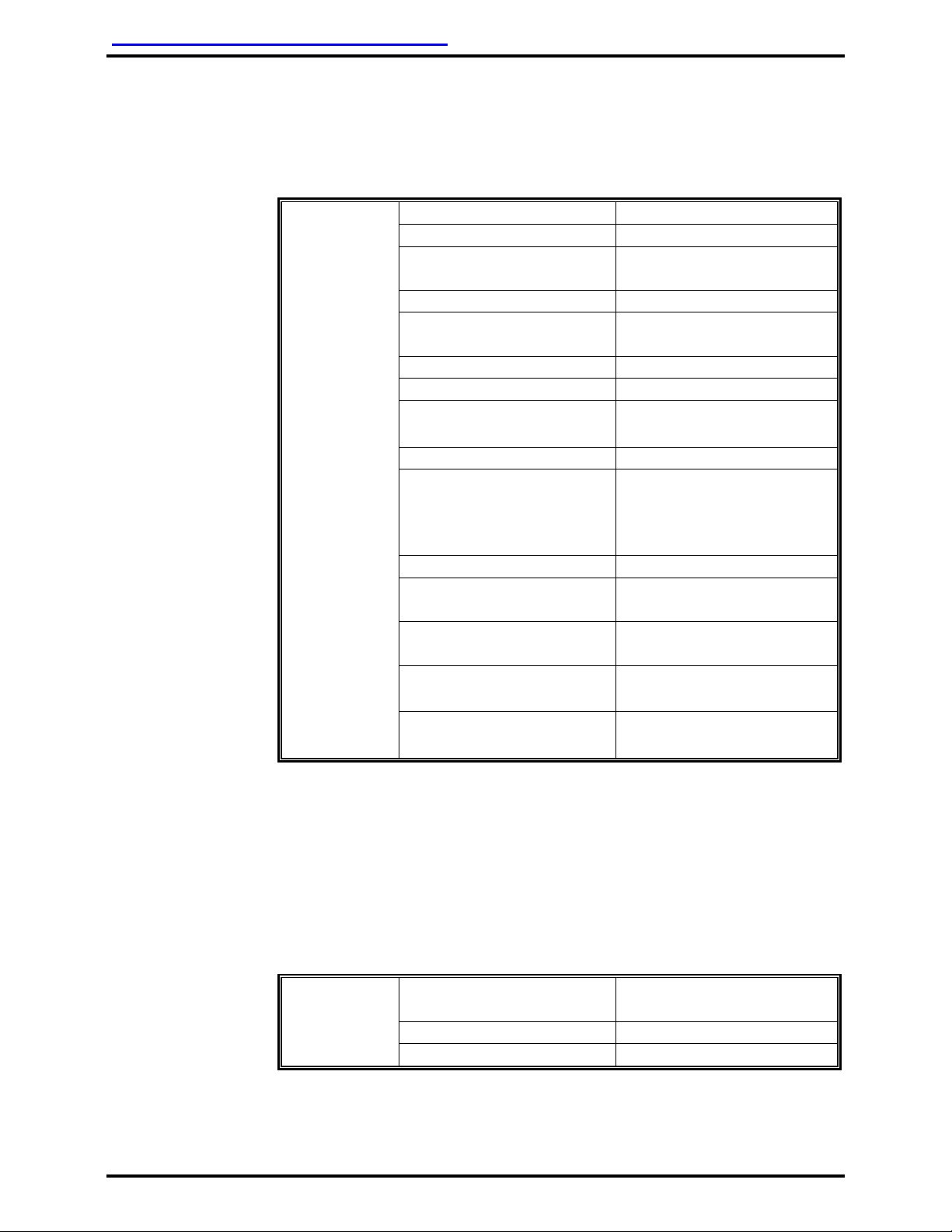
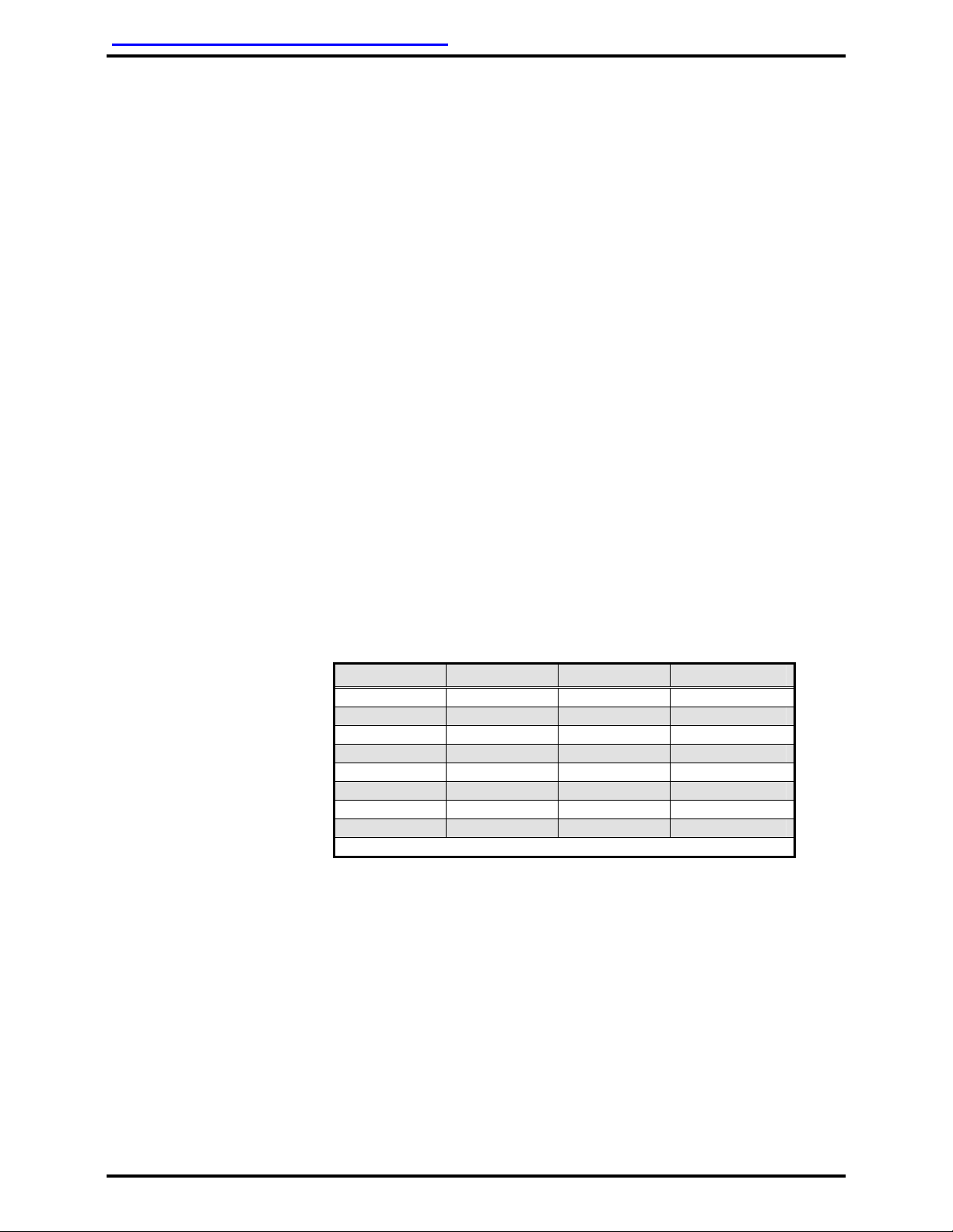
A typical Monitor Setup Menu consists of the following modes:
1. “OSD TIMEOUT”- Timeout period until monitor defaults out of menu mode.
2. “BACKLIGHT”- Backlighting intensity.
3. “FACTORY PRESET”- All modes may be reset to the default factory setting. Select
either “YES” or “NO”.
4. “SOURCE PRIORITY”- Selects priority operating mode to “PC” (personal computer)
or “None”. Setting this mode to “PC” allows user to normally view composite video
until a PC laptop is turned on, then the monitor will automatically switch to PC input
upon sensing VGA input.
5. “H-POS”- Adjusts viewing area horizontally.
6. “V-POS”- Adjusts viewing area vertically.
7. “SHARPNESS”- Adjusts picture sharpness.
8. “COLOR”- Adjusts picture color.
9. “TINT”- Adjusts picture tint.
10. “CONTRAST”- Adjusts picture contrast.
11. “BRIGHT”- Adjusts picture brightness.
The setup menu may vary slightly from monitor model to model. As
technology advances, additional features may be added to the setup
menu and existing features may be modified. DeCrane Aerospace Audio
International’s intention is to provide clear and concise instructions on any
new or modified feature in the setup menu as these changes occur.
4.0 Instructions for Continued Airworthiness
4.1 Airworthiness Limitations
No periodic scheduled maintenance or calibration is required for continued
airworthiness of the LCD-9121-101-x. If the unit fails to perform to
specifications, it must be removed and serviced by a qualified service
facility.

DeCrane Aerospace Audio International, Inc. LCD-9121-101-x Installation Manual
Document # 540365, Rev IR, 03/2008 Page 14 of 18
4.2 Cleaning Method
The LCD-9121-101-x should be cleaned when excessive dust or dirt
becomes apparent.
Use a twin pack cleaning system that employs a wet pad pre-moistened
with an Isopropyl Alcohol based cleaner/anti-static solution and a lint-free
drying cloth. DeCrane Aerospace Audio International recommends using
“Kleen & Dry” RR1205 manufactured by READ RIGHT, Nanuet, NY
10954.
Do not use benzene, ammonia, thinner, or any other volatile
substance to clean the monitor or screen. These chemicals may
damage the screen or internal circuitry.
Do not allow cleaner to puddle or pool around edges. Seepage
may damage internal circuitry.
DeCrane Aerospace Audio International’s recommended cleaning method
follows:
A. Turn off monitor.
B. Open pre-moistened pad and gently wipe evenly across display
glass. Do not allow solution to “pool” or puddle around display
edges.
C. Immediately dry display using the absorbent, lint-free cloth. Gently
wipe display to a dry, clear finish.
4.3 General Troubleshooting Procedures
•Verify power to the unit by rechecking +28 VDC power is applied to the
proper pins on the unit. Use a voltmeter to verify correct level.
•Remove power from the unit for at least one (1) minute and reapply
power.
•Recheck all connections to the unit for security. Check all harness runs
for possible pinching. Recheck all pinouts for application accuracy.
•Check data bus integrity by utilizing a voltmeter, oscilloscope, or other
voltage instrument to verify proper input voltage on the data bus pins.
Typical measurements are as follows:
A to Ground: 4.0 to 4.5 VDC
B to Ground: 0.1 to 1.0 VDC
If any device is transmitting (i.e., holding bus active), then these typical
measurements would be reversed for the A-to-Ground and
B-to-Ground. This troubleshooting tool can help indicate a data bus

DeCrane Aerospace Audio International, Inc. LCD-9121-101-x Installation Manual
Document # 540365, Rev IR, 03/2008 Page 15 of 18
lockup. If this occurs, remove the data bus from all other equipment
one piece at a time. As each is removed, check the bus status to see if
it is now functioning properly. Once you have removed the piece or
pieces of offending equipment, disconnect power and then reconnect
everything but the suspect component. Reapply power and then test
the functionality of the unit(s).
4.4 Troubleshooting Chart
Problem Possible Cause Solution
Poor picture quality or
scrambled video
LCD backlight malfunction
SP-LCD6 programming
Poor video source
Contact DAAI
Check setup
Verify function of
video source
Blank screen*
LCD not receiving power
Mother board malfunctioning
Check all cable
connections
Contact DAAI
*The monitor displays a black screen with the unit turned on and no video
signal.
5.0 Specifications
5.1 Unit Specifications for LCD-9121-101-x:
Physical Specifications – LCD-9121-101-x
Screen Size 12.10 (30.73 cm) diagonal
Weight 4.01 lb / 1.82 kg
Dimensions
(l x w x h) 11.34" x 1.39" x 8.66"
28.80 cm x 3.53 cm x 22.00 cm
5.2 Unit Specifications for SP-LCD6:
Physical Specifications – SP-LCD6
Bezel Plating Raw, unless otherwise specified
Weight Approx. 0.13 lb / 0.06 kg
with connector
Dimensions
(l x w x h) 2.38" x 2.53" x 1.29"
6.05 cm x 6.43 cm x 3.28 cm

DeCrane Aerospace Audio International, Inc. LCD-9121-101-x Installation Manual
Document # 540365, Rev IR, 03/2008 Page 16 of 18
6.0 Reference Drawings
6.1 LCD-9121-101-x
The following diagrams show the unit dimensions, mounting locations, and
connector locations for the LCD-9121-101-x.

DeCrane Aerospace Audio International, Inc. LCD-9121-101-x Installation Manual
Document # 540365, Rev IR, 03/2008 Page 17 of 18
Grounding Stud
LCD-9121-101-x connector configuration shown

DeCrane Aerospace Audio International, Inc. LCD-9121-101-x Installation Manual
Document # 540365, Rev IR, 03/2008 Page 18 of 18
6.2 External Menu Switch
The following diagrams show the unit dimensions and connector locations
for the external menu selection switch, SP-LCD6.
Table of contents
Other decrane aerospace Monitor manuals

decrane aerospace
decrane aerospace LCDW-9230-101-x User manual

decrane aerospace
decrane aerospace LCDP-9151-201 User manual

decrane aerospace
decrane aerospace LCDW-9190-101-x User manual

decrane aerospace
decrane aerospace LCDHW-420-BN1-x User manual

decrane aerospace
decrane aerospace TSC-9104-101-X User manual

decrane aerospace
decrane aerospace LCDW-9320-101-X User manual

decrane aerospace
decrane aerospace LCDP-9084-301-x User manual

decrane aerospace
decrane aerospace lcd-9084-301-x User manual