decrane aerospace LCDHW-420-BN1-x User manual

7300 Industry Drive, North Little Rock, AR 72117
Phone: 501-955-2929 Fax: 501-955-2988
www.decraneaerospace.com
Installation Manual
LCDHW-420-BN1-x
42" High Definition Widescreen LCD Monitor
Document # 540390

DeCrane Aerospace Audio International LCDHW-420-BN1-x Installation Manual
Document # 540390, Rev IR, 08/2010 Page 1 of 16
Document Revision History
Rev. Level
Date
Des
cription
IR 08/2010 Initial Release
Reference Documents
(or latest revision)
Document #
Description
526403 Rev B LCDHW-420-BN1-x Outline Drawing
Service Bulletin List
Service
Bulletin # Subject
Manual
Revision
Revision
Date
Table of Illustrations
Section #
Description
Page #
2.3 Block Diagram - Typical Application 4
7.0 Reference Drawings 14-16
PROPRIETARY NOTICE: Despite any other copyright notice, this document and information
disclosed herein contains confidential, proprietary designs owned by DeCrane Aerospace Audio
International. Neither this document nor the data contained herein shall be
reproduced, used, or
disclosed to anyone without the written authorization of DeCrane Aerospace Audio International.

DeCrane Aerospace Audio International LCDHW-420-BN1-x Installation Manual
Document # 540390, Rev IR, 08/2010 Page 2 of 16
Table of Contents
Section
Description Page
1.0
General Information
. . . . . . . . . . . . . . . . . . . . . . . . . . . . . . . .
3
1.1
Introduction . . . . . . . . . . . . . . . . . . . . . . . . . . . . . . . . . . . . . . . . 3
1.2
Purpose of the Equipment . . . . . . . . . . . . . . . . . . . . . . . . . . . . .
3
1.3
Optional Equipment . . . . . . . . . . . . . . . . . . . . . . . . . . . . . . . . . .
3
2.0
Application
. . . . . . . . . . . . . . . . . . . . . . . . . . . . . . . . . . . . . . .
.
3
2.1
Introduction . . . . . . . . . . . . . . . . . . . . . . . . . . . . . . . . . . . . . . . . 3
2.2
Communication . . . . . . . . . . . . . . . . . . . . . . . . . . . . . . . . . . . . . 4
2.3
Block Diagram - Typical Application. . . . . . . . . . . . . . . . . . . . . .
4
2.4
Typical Interface . . . . . . . . . . . . . . . . . . . . . . . . . . . . . . . . . . . . 4
3.0
Installati
on
. . . . . . . . . . . . . . . . . . . . . . . . . . . . . . . . . . . . . . .
.
5
3.1
Prior to Installation . . . . . . . . . . . . . . . . . . . . . . . . . . . . . . . . . . 5
3.2
Unpacking and Inspection . . . . . . . . . . . . . . . . . . . . . . . . . . . . .
6
3.3
Cautions & Warnings . . . . . . . . . . . . . . . . . . . . . . . . . . . . . . . . 6
3.4
Wiring Requirements . . . . . . . . . . . . . . . . . . . . . . . . . . . . . . . . .
7
3.5
Electrical Characteristics . . . . . . . . . . . . . . . . . . . . . . . . . . . . . .
8
3.6
Mating Connector Information . . . . . . . . . . . . . . . . . . . . . . . . . .
9
3.7
Pinout Assignment Descriptions . . . . . . . . . . . . . . . . . . . . . . . . 10
4.0
Instructions for Continu
ed Airworthiness
. . . . . . . . . . . . . .
1
1
5.0
Troubleshooting
. . . . . . . . . . . . . . . . . . . . . . . . . . . . . . . . . .
.
1
1
5.1
Cleaning Method . . . . . . . . . . . . . . . . . . . . . . . . . . . . . . . . . . . . 11
5.2
General Troubleshooting Procedures . . . . . . . . . . . . . . . . . . . . 12
5.3
Troubleshooting Chart . . . . . . . . . . . . . . . . . . . . . . . . . . . . . . . .
13
6.0
Specifications . . . . . . . . . . . . . . . . . . . . . . . . . . . . . . .
. . . . .
.
1
3
7.0
Reference Drawings . . . . . . . . . . . . . . . . . . . . . . . . . . . . . . . .
14

DeCrane Aerospace Audio International LCDHW-420-BN1-x Installation Manual
Document # 540390, Rev IR, 08/2010 Page 3 of 16
LCDHW-420-BN1-x
42
"
High Definition Widescreen LCD Monitor
1.0 General Information
1.1 Introduction
This manual contains information for the proper installation of the
DeCrane Aerospace Audio International 42" High Definition Widescreen
Liquid Crystal Display (LCD) Monitor, Model No: LCDHW-420-BN1-x. The
“-x” suffix designates the type of connector utilized; “-1” = Positronic and
“-2” = D-Subminiature. Also included are physical and electrical
characteristics of the unit.
1.2 Purpose of the Equipment
DeCrane Aerospace Audio International’s LCDHW-420-BN1-x is a 42"
High Definition Widescreen monitor with a 1920 x 1080 wide aspect ratio
WUXGA resolution with a color depth of 10-bits (1.06 billion colors). This
is a Color Active Matrix Liquid Crystal Display capable of accepting up to
1920 x 1080p video signals via a HDMI interface or a 3G-SDI interface.
This LCD provides accurate color reproduction, has high brightness and
contrast ratio, wide viewing angles, and fast response time. The monitor is
designed for bulkhead mounting.
1.3 Optional Equipment
DeCrane Aerospace Audio International offers a comprehensive family of
Cabin Control Modules and Source Equipment. These modules provide
convenient solutions for a variety of frequently encountered interfacing
needs or special requirements and are an important part of DeCrane
Aerospace Audio International’s “building block” system for configuring
total cabin management.
2.0 Application
2.1 Introduction
The LCDHW-420-BN1-x is a 42.0" Wide Screen High Definition LCD
monitor with HDMI and 3G-SDI input.

DeCrane Aerospace Audio International LCDHW-420-BN1-x Installation Manual
Document # 540390, Rev IR, 08/2010 Page 4 of 16
2.2 Communication
This unit incorporates an IEEE 802.3 compliant Ethernet interface for
communication purposes to other network-connected devices. The
Ethernet protocol is compliant to DeCrane Aerospace Audio International’s
Ethernet Specification document 480032.
2.3 Block Diagram - Typical Application
2.4 Typical Interfaces
2.4.1 3G-SDI video input (x1) accepts full 1920 x 1080p high
definition video in 3G-SDI format compliant with DeCrane
Aerospace Audio International video source equipment.
2.4.2 Device addressing is accomplished via four (4) ID pins
for a total of sixteen monitors to be independently
addressed on the network.

DeCrane Aerospace Audio International LCDHW-420-BN1-x Installation Manual
Document # 540390, Rev IR, 08/2010 Page 5 of 16
3.0 Installation
3.1 Prior to installation, the following items should be considered:
3.1.1 During the design and layout of the aircraft cabin, careful
consideration of the location of this module is necessary. Some of
the items to be considered include:
•Space
•Available power supply
•Environmental conditions (temperature, humidity, etc.)
•Length of cable runs
3.1.2 The LCDHW-420-BN1-x shall be installed to conform to the
standards designated by the customer, installing agency, and
existing conditions as to the unit location and type of installation.
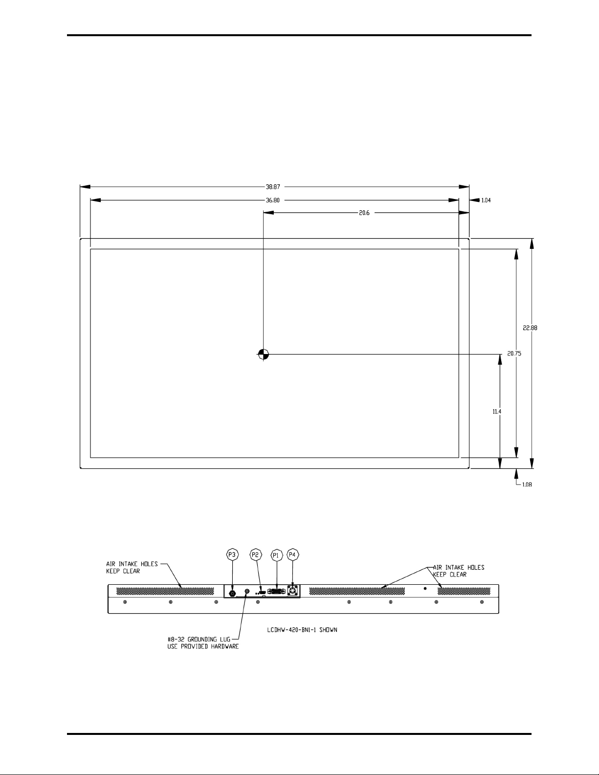
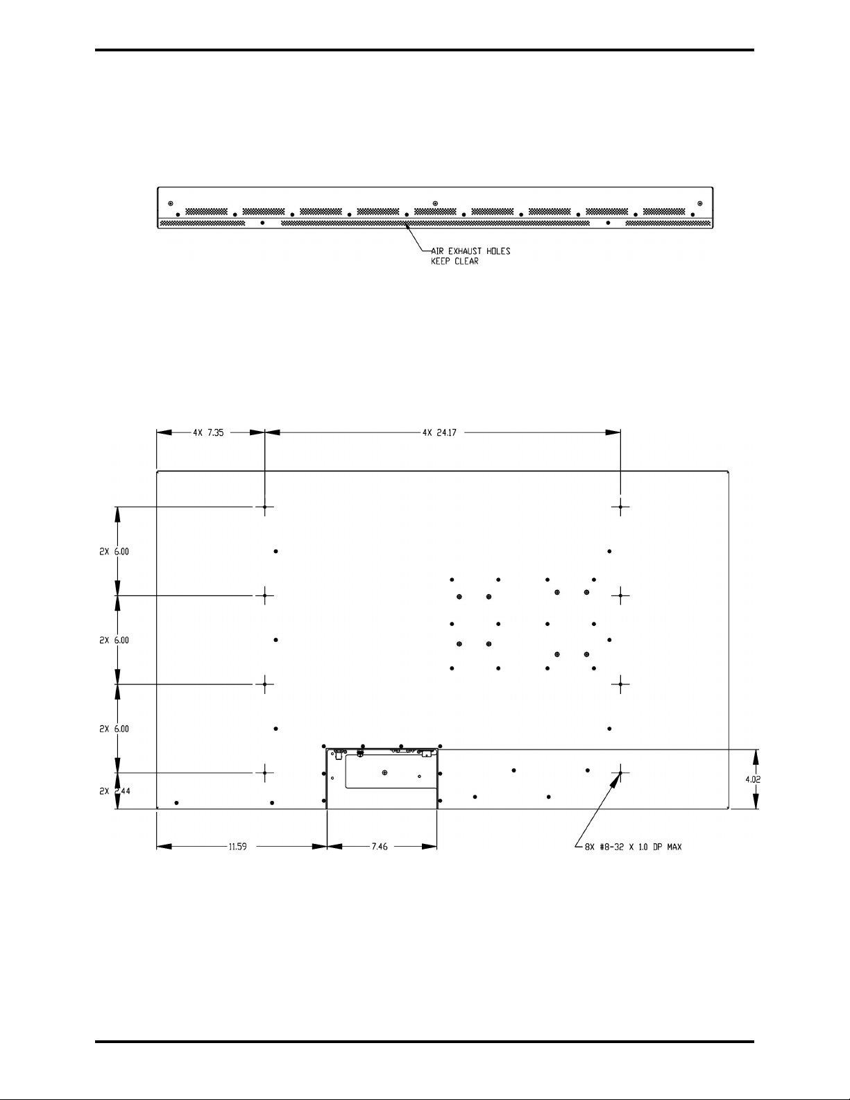
3.1.3 An internal cooling fan ventilates internal components and prevents
undesirable heat buildup. Proper ventilation must be allowed for
when specifying the installation location. The closeout area of the
monitor shall have a clearance of 2 inches (5.08 cm) minimum for
the air inlet and exit areas. The closeout area of the monitor case
shall not block the air inlet or exhaust openings of the monitor case.
This fan is thermostatically controlled, it only runs when the unit is
turned on and heat build-up requires it, providing a much quieter
viewing experience than many monitors.
3.1.4 The monitor casing is specially designed for EMI and noise filtering,
guaranteeing a reduction in interference to ensure a high-quality
display.
3.1.5 A shallow mounting depth makes this monitor ideal for bulkhead
use. Convenient mounting holes are strategically located on the left
and right sides, as well as the back of the unit. The unit has eight
(8) 8-32 UNF-2B on the left and right sides, four (4) on each side.
The maximum depth should be no more than 0.50 inches. In
addition, the unit has eight (8) 8-32 UNF-2B on the back. The
maximum depth should be no more than 1 inch. Refer to Section
7.0, Reference Drawings, for mounting hole diameters and
configuration.
3.1.6 The monitor should be located as close to the source equipment as
possible in order to reduce the possibility of noise introduced into
the video. Refer to Section 6.0 for unit dimensions.
3.1.7 A grounding lug is included as part of the housing. See Section 7.0
for details.

DeCrane Aerospace Audio International LCDHW-420-BN1-x Installation Manual
Document # 540390, Rev IR, 08/2010 Page 6 of 16
3.1.8 The maximum length of the connection to PC Graphic (VGA) input
is 15 feet.
3.2 Unpacking and Inspection
3.2.1 Carefully open the packaging and remove the LCDHW-420-BN1-x.
Verify that all components have been included in the package per
the packing list. Inspect the unit for damage. Retain the packing
materials and packing list.
3.2.2 If damage has occurred during shipping, a claim should be filed
with DeCrane Aerospace Audio International WITHIN 24 hours and
a Return Request Authorization Number shall be obtained from
DeCrane Aerospace Audio International by contacting the Repair
Department at 501.801.8101. Repackage the unit in its original
packaging materials and return it to DeCrane Aerospace Audio
International following instructions given by the DeCrane
Aerospace Audio International representative. Refer to the front
cover of this manual for address. If no return is necessary, retain
the packing list and the packing materials for storage.
3.3 Cautions and Warnings
3.3.1 It is important to do a pin-to-pin power and ground check on all
connectors. Ensure that power and ground are applied only where
specified. Damage to the unit may result if power or ground is
applied to the wrong points.
3.3.2 DO NOT connect or disconnect the monitor while power is applied.
3.3.3 DO NOT remove any factory-installed screws. Damage to the unit
may result and void any warranties.
3.3.4 DO NOT expose to moisture.
3.3.5 ESD (Electro Static Discharge) guidelines shall be followed.

DeCrane Aerospace Audio International LCDHW-420-BN1-x Installation Manual
Document # 540390, Rev IR, 08/2010 Page 7 of 16
3.4 Wiring Requirements
3.4.1 Introduction
The installing agency shall supply and fabricate all external cables
and mating connectors. The length and routing of external cables
should be carefully studied and planned before attempting
installation of the equipment. Allow adequate space for installation
of cable and connectors. Avoid sharp bends and placing cables
near aircraft control cables. Maintain a minimum clearance of three
(3) inches from any control cable. If wiring is run parallel to
combustible fluid or oxygen lines, maintain a separation of six (6)
inches between the lines.
3.4.2 Bonding
Chassis ground connection shall be electrically bonded to the
airframe structure by the grounding lug using a braided copper
bonding strap with <0.01 resistance.
3.4.3 Power Wires
Power and Ground wires shall be in accordance with M22759 or
equivalent. Protect power wires with circuit breakers or fuses
located close to the electrical power source bus.
3.4.4 AES3 Audio
All AES3 digital audio connections are recommended to use
shielded twisted cable with a cable impedance of 110 +/- 10%
with the shield properly bonded at the both ends. PIC Wire and
Cable, part number E10224 or equivalent is recommended.
3.4.5 3G-SDI Video
All 3G-SDI digital video connections are recommended to use
shielded coaxial cable from PIC Wire and Cable, part number
V78209, using a single run of cable no greater than 50 meters.
BNC connectors with an impedance of 75-ohm should be used
where cable discontinuities may occur.

DeCrane Aerospace Audio International LCDHW-420-BN1-x Installation Manual
Document # 540390, Rev IR, 08/2010 Page 8 of 16
3.4.5 HDMI Video
All HDMI digital video connections are recommended to use
Electronic Cable Specialists HDMI cable, part number 600-19786
or equivalent, using a single run of cable no greater than 15 meters.
Discontinuities in this cable are not recommended.
3.4.6 Ethernet Connections
Ethernet connection is recommended to use PIC Wire and Cable
part number E51424 or equivalent.
3.4.7 Single Signal Connections
All single signal connections are recommended to use 22AWG
(minimum) in accordance with MIL-W-22759 or equivalent.
3.5 Electrical Characteristics
3.5.1 Electrical Specifications for LCDHW-420-BN1-x:
Electrical Nominal Power 1.2 A @ +115 VAC
Maximum Power 1.8 A @ +115 VAC
Operating Voltage Range +85 to +150 VAC
Screen Size 42" (106.68 cm) diagonal
Screen Resolution 1920 x 1080p (H x V)
Contrast Ratio 1400:1
Aspect Ratio 16:9
Luminance 500 cd/m²
Color Depth 10-bits, 1.07 billion colors
Viewing Angle 89°Up/Down/Lft/Rgt
Video Input 3G-SDI and HDMI
Video Format Composite (SECAM,
PAL, and NTSC), and WUXGA
PC Graphics
Operating Temperature +5°to +131°F
-15°to +50°C
Storage Temperature -4°to +140°F
-20°to +60°C
3.5.2 The LCDHW-420-BN1-x utilizes four (4) connectors. P1 is a 15-pin
connector that provides Ethernet control. Four (4) ID pins are also
provided on the P1 connector. These ID pins allow for up to 16
units to be connected on the same DeCrane Aerospace Audio
International’s Ethernet network while maintaining independent
control of each unit.

DeCrane Aerospace Audio International LCDHW-420-BN1-x Installation Manual
Document # 540390, Rev IR, 08/2010 Page 9 of 16
3.5.3 P2 is a 19-pin connector that provides HDMI connectivity.
3.5.4 P3 is a BNC connection that provides HDSDI connectivity.
3.5.5 P4 is a 6-pin Amphenol connector that provides power input and
ground.
3.6 Mating Connector Information
All wiring harnesses to the unit shall be supplied and fabricated by the
installing agency.
P1 CONNECTOR:
PART NUMBER
MATING CONNECTOR
LCDHW-420-BN1-1 RD15F10JVL0 Male Plug or equivalent
(Positronic Industries)
LCDHW-420-BN1-2 DEMA-15S Female Plug with
male jackscrews or equivalent
(ITT Cannon)
P2 CONNECTOR:
P3 CONNECTOR:
PART NUMBER
MATING CONNECTOR
LCDHW-420-BN1-1 BNC Plug
LCDHW-420-BN1-2 BNC Plug
P4 CONNECTOR:
PART NUMBER
MATING CONNECTOR
LCDHW-420-BN1-1 MS3126F10-6S Amphenol
LCDHW-420-BN1-2 MS3126F10-6S Amphenol
PART NUMBER
MATING CONNECTOR
LCDHW-420-BN1-1 HDMI Plug
LCDHW-420-BN1-2 HDMI Plug

DeCrane Aerospace Audio International LCDHW-420-BN1-x Installation Manual
Document # 540390, Rev IR, 08/2010 Page 10 of 16
3.7 Pinout Assignment Descriptions
Pinout assignment for the LCDHW-420-BN1-x is as follows:
P
1
Pin #
Description
1-2 Reserved
3 Ethernet RX+
4 Ethernet RX-
5 Ethernet TX+
6 Ethernet TX-
7 Ethernet Shield
8 ID Common
9 ID Bit 0
10 ID Bit 1
11 ID Bit 2
12 ID Bit 3
13 AES3 +
14 AES3 -
15 AES3 Shield
P
2
Pin #
Description
1 HDMI RX2 P
2 HDMI RX2 Shield
3 HDMI RX2 N
4 HDMI RX1 P
5 HDMI RX1 Shield
6 HDMI RX1 N
7 HDMI RX0 P
8 HDMI RX0 Shield
9 HDMI RX0 N
10 HDMI CLK P
11 HDMI CLK Shield
12 HDMI CLK N
13 Reserved
14 Reserved
15 DDC CLK 0
16 DDC Data 0
17 DDC Ground
18 Power 5V
19 HPD

DeCrane Aerospace Audio International LCDHW-420-BN1-x Installation Manual
Document # 540390, Rev IR, 08/2010 Page 11 of 16
P
3
Pin #
Description
1 HDSDI P
2 HDSDI Return
P
4
Pin #
Description
A 115 VAC 400HZ Hot
B 115 VAC 400HZ Ground
C 115 VAC 400HZ Neutral
D-F Reserved
4.0 Instructions for Continued Airworthiness
No periodic scheduled maintenance or calibration is required for continued
airworthiness of the LCDHW-420-BN1-x. If the unit fails to perform to
specifications, it must be removed and serviced by a qualified service facility.
5.0 Troubleshooting
5.1 Cleaning Method
The LCDHW-420-BN1-x should be cleaned when excessive dust or dirt
becomes apparent.
Use a twin pack cleaning system that employs a wet pad pre-moistened
with an Isopropyl Alcohol based cleaner/anti-static solution and a lint-free
drying cloth. DeCrane Aerospace Audio International recommends using
“Kleen & Dry” RR1205 manufactured by READ RIGHT, Nanuet, NY
10954.
Do not use benzene, ammonia, thinner, or any other volatile
substance to clean the monitor or screen. These chemicals may
damage the screen or internal circuitry.
Do not allow cleaner to puddle or pool around edges. Seepage
may damage internal circuitry.

DeCrane Aerospace Audio International LCDHW-420-BN1-x Installation Manual
Document # 540390, Rev IR, 08/2010 Page 12 of 16
DeCrane Aerospace Audio International’s recommended cleaning method
follows:
A. Turn off monitor.
B. Open pre-moistened pad and gently wipe evenly across
display glass. Do not allow solution to “pool” or puddle
around display edges.
C. Immediately dry display using the absorbent, lint-free cloth.
Gently wipe display to a dry, clear finish.
5.2 General Troubleshooting Procedures
•Verify power to the unit by rechecking +28 VDC power is applied to the
proper pins on the unit. Use a voltmeter to verify correct level.
•Remove power from the unit for at least one (1) minute and reapply
power.
•Recheck all connections to the unit for security. Check all harness runs
for possible pinching. Recheck all pinouts for application accuracy.
•Check data bus integrity by utilizing a voltmeter, oscilloscope, or other
voltage instrument to verify proper input voltage on the data bus pins.
Typical measurements are as follows:
A to Ground: 4.0 to 4.5 VDC
B to Ground: 0.1 to 1.0 VDC
If any device is transmitting (i.e., holding bus active), then these typical
measurements would be reversed for the A-to-Ground and
B-to-Ground. This troubleshooting tool can help indicate a data bus
lockup. If this occurs, remove the data bus from all other equipment
one piece at a time. As each is removed, check the bus status to see if
it is now functioning properly. Once you have removed the piece or
pieces of offending equipment, disconnect power and then reconnect
everything but the suspect component. Reapply power and then test
the functionality of the unit(s).

DeCrane Aerospace Audio International LCDHW-420-BN1-x Installation Manual
Document # 540390, Rev IR, 08/2010 Page 13 of 16
5.3 Troubleshooting Chart
Problem
Possible Cause
Solution
Poor picture quality or
scrambled video
LCD backlight malfunction
SP-LCD6 programming
Poor video source
•Contact DeCrane
Aerospace Audio
International
•Check setup
•Verify function of
video source
Blank screen*
LCD not receiving power
Mother board malfunctioning
•Check all cable
connections
•Contact DeCrane
Aerospace Audio
International
*The monitor displays a black screen with the unit turned on and no video
signal.
6.0 Specifications
Unit Specifications for LCDHW-420-BN1-x:
Physical Specifications
–
LCD
H
W
-
420
-
BN
1
-
x
Housing Iridited Aluminum
(with black powder-coat finish)
Screen Size 42" (106.68 cm) diagonal
Weight Approx. 41.00 ± 1.00 lbs / 18.68 ± 0.45 kg
Dimensions
(l x w x h) 38.87" x 2.85" x 22.88"
98.73 cm x 7.24 cm x 58.12 cm
Note: This does not including optional bezel and bezel mounting bracket.

DeCrane Aerospace Audio International LCDHW-420-BN1-x Installation Manual
Document # 540390, Rev IR, 08/2010 Page 14 of 16
7.0 Reference Drawings
LDCHW-420-BN1-x – High Definition Widescreen LCD Monitor
The following diagrams show the unit dimensions, mounting locations, and
connector locations for the LCDHW-420-BN1-x.
Front View
Bottom View
LCDHW-420-BN1-x Connector Configuration

DeCrane Aerospace Audio International LCDHW-420-BN1-x Installation Manual
Document # 540390, Rev IR, 08/2010 Page 15 of 16
Top View
Back View

DeCrane Aerospace Audio International LCDHW-420-BN1-x Installation Manual
Document # 540390, Rev IR, 08/2010 Page 16 of 16
Side View
Table of contents
Other decrane aerospace Monitor manuals

decrane aerospace
decrane aerospace lcd-9084-301-x User manual

decrane aerospace
decrane aerospace LCD-9121-101 SERIES User manual

decrane aerospace
decrane aerospace LCDP-9151-201 User manual

decrane aerospace
decrane aerospace LCDW-9190-101-x User manual

decrane aerospace
decrane aerospace LCDW-9320-101-X User manual

decrane aerospace
decrane aerospace LCDW-9230-101-x User manual

decrane aerospace
decrane aerospace TSC-9104-101-X User manual

decrane aerospace
decrane aerospace LCDP-9084-301-x User manual