Dectris PILATUS 300K-W User manual

Technical Specification
and
Operating Procedure
PILATUS 300K-W
Detector System
Version 1.7

Technical_Specification_PILATUS_300K-W_V1_7 2/28
Table of Contents
1DOCUMENT HISTORY ................................................................................................................ 3
1.1 CHANGES....................................................................................................................................... 3
2HOW TO USE THIS TECHNICAL SPECIFICATION .......................................................................... 4
2.1 ADDRESS AND SUPPORT ................................................................................................................... 4
2.2 EXPLANATION OF SYMBOLS ............................................................................................................... 5
2.3EXPLANATION OF TERMS .................................................................................................................. 5
2.4 USE OF THE PILATUS 300K-W ........................................................................................................ 5
3TECHNICAL SPECIFICATIONS...................................................................................................... 6
3.1 RATINGS........................................................................................................................................ 7
3.2 AMBIENT CONDITIONS ..................................................................................................................... 8
4DIMENSIONS AND CONNECTORS .............................................................................................. 9
4.1 PILATUS 300K-W DETECTOR .......................................................................................................... 10
4.1.1 Front Side of the Detector............................................................................................... 10
4.1.2 Backside of the Detector................................................................................................. 11
4.1.3 The Status LEDs...............................................................................................................12
4.1.4 Connectors and Connecting Cables/Pipes.......................................................................12
4.2 POWER SUPPLY............................................................................................................................. 14
4.3 COMPUTER .................................................................................................................................. 15
5INSTALLING THE DETECTOR SYSTEM ....................................................................................... 16
5.1 MOUNTING.................................................................................................................................. 16
5.1.1 Mounting from Above..................................................................................................... 16
5.1.2 Mounting from Below.....................................................................................................17
5.2 GROUNDING OF THE DETECTOR SYSTEM ............................................................................................ 18
5.3 CONNECTION TO NITROGEN OR DRY AIR............................................................................................ 19
5.4 CONNECTING THE CABLES ............................................................................................................... 20
6TEMPERATURE AND HUMIDITY CONTROL .............................................................................. 21
7GETTING STARTED .................................................................................................................. 23
7.1 STARTUP SEQUENCE ...................................................................................................................... 23
7.2 FIRST COMMANDS......................................................................................................................... 24
8TURNING OFF THE DETECTOR ................................................................................................. 25
9STORING THE DETECTOR ......................................................................................................... 25
10 CLEANING AND MAINTENANCE .............................................................................................. 26
11 FAULTS.................................................................................................................................... 27
12 CERTIFICATION TESTS ............................................................................................................. 28

Technical_Specification_PILATUS_300K-W_V1_7 3/28
1 Document History
Actual document
Version
Date
status
prepared
checked
released
1.7
22.07.2011
released
PS, BS
SC, DB
BS
1.1 Changes
Version
Date
Changes
released
1.0
27.04.2009
First release
PS
1.4
29.01.2010
Connection cables and
temperature sensors
BS
1.4.1
15.02.2010
Power supply
BS
1.4.2
18.02.2010
Signal levels
BS
1.5
09.04.2010
Dimensions and grounding
BS
1.5.1
28.05.2010
Dimensions
BS
1.6
04.10.2010
Pictures
BS
1.7
22.07.2011
Thicker sensors and conformity
with standards
BS

Technical_Specification_PILATUS_300K-W_V1_7 4/28
2 How to use this Technical
Specification
Before you start to operate the PILATUS 300K-W detector system please
read this technical specification and the user manual thoroughly.
The technical specification and the user manual together form the user
documentation.
2.1 Address and Support
DECTRIS Ltd.
Neuenhoferstrasse 107
5400 Baden
Switzerland
Phone: +41 56 500 21 00
Fax: + 41 56 500 21 01
Should you have questions concerning the system or its use, please contact
us via phone, mail or fax.
Before you ship the system back, please contact us to receive the
necessary transport and shipping information.

Technical_Specification_PILATUS_300K-W_V1_7 5/28
2.2 Explanation of Symbols
Symbol
Description
Important or helpful notice
Caution. Please follow the instructions carefully to prevent
equipment damage or personal injury.
DC-current
AC-current
Ground
2.3 Explanation of Terms
Term
Description
MCB
Module Control Board
DCB
Detector Control Board
DAC
Digital to Analog Converter
2.4 Use of the PILATUS 300K-W
The PILATUS 300K-W detector system has been designed for the detection
of X-rays from synchrotrons or laboratory sources.
It is intended for indoor use only.
For other applications, please contact DECTRIS for additional information.
Do not use the detector in vacuum.
The PC can be mounted in a standard 19 inch rack, which has to be properly
grounded.
Make sure that the PC has adequate ventilation.

Technical_Specification_PILATUS_300K-W_V1_7 6/28
3 Technical Specifications
Number of modules
3 x 1 = 3
Sensor
Reverse-biased silicon diode array
Sensor thickness
320 µm 450 µm
3 keV: 48%
8 keV: 95%
15 keV: 51%
3 keV: 48%
8 keV: 96%
15 keV: 64%
Pixel size
172 x 172 µm2
Module size
83.8 x 33.5 mm2
Format
1475 x 195 = 287'625 pixels
Area
254 x 33.5 mm2
Intermodule gap
X: 7 pixels, 1% of total range
Dynamic range
20 Bits = 1’048’576
Counting rate per pixel
> 2x10⁶X-ray/sec
Energy range
4.5 –36 keV
Energy resolution
500 eV
Adjustable threshold range
4 –18 keV
Threshold dispersion
50 eV
Readout time
2.3 ms
Framing rate
Standard: 100 Hz, Fast: 200 Hz
Point-spread function
1 pixel
Data formats
Raw data, TIF, EDF, CBF
External trigger/gate
3.3 - 5V, 3 different modes
Software interface
Through socket connection;
Clients for EPICS, SPEC and stand-alone
operation are available
Cooling
Air-cooled
Operating temperature (internal)
20-35°C
Dimensions (W x H x D)
332 x 170 x 356 mm
Weight
14 kg
Technical_Specification_PILATUS_300K-W_V1_7 7/28
3.1 Ratings
Device
Definition
Detector
Power Input
+12 V DC, 4 A, 48 Watt
Power Supply
90-260 VAC, 47/63 Hz
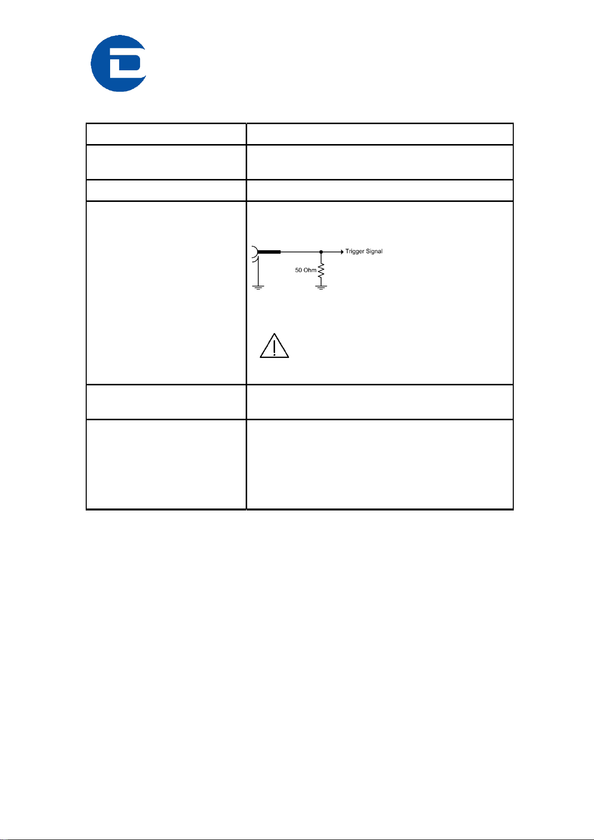
Detector
External Trigger Input
2.0 V - 5.0 V High level
0.0 V - 0.8 V Low level
50 Ohm Impedance
Trigger Signal … to internal circuit
5.0 V absolute maximum
Applying a higher voltage will destroy
the input.
Detector
Enable Output
5 V TTL (max. 100 mA)
PC
100 - 240 VAC; 12 A
50/60 Hz
870 Watt
Hot-Plug Power Supplies
Can be connected to all common supply
voltages.

Technical_Specification_PILATUS_300K-W_V1_7 8/28
3.2 Ambient Conditions
The PILATUS 300K-W detector is designed only for indoor use. The following
ambient conditions must be fulfilled:
Condition
Range
Operating temperature:
+20° to +35°C
Operating humidity:
< 80% at 20°C, non-condensing
Storage temperature
+15° to +40°C
Storage humidity
< 40% at 20°C, non-condensing
Note that the interior humidity under operating conditions must be
< 25%, see section 6.
When storing the detector make sure the temperature and humidity
inside the transport box doesn’t exceed the specified range. Use drying agent.
If the detector system is stored at low temperature, make sure that
no condensation moisture develops.
The PILATUS 300K-W is equipped with a temperature and humidity
control, see section 6.
Technical_Specification_PILATUS_300K-W_V1_7 9/28
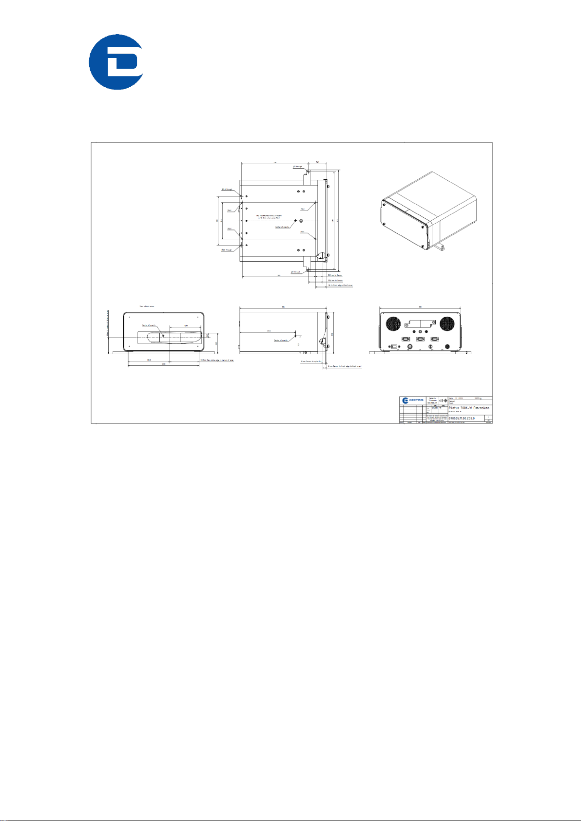
4 Dimensions and Connectors
Figure 1. Drawing of the PILATUS 300K-W detector (printed separately in the user
documentation folder)

Technical_Specification_PILATUS_300K-W_V1_7 10/28
4.1 Pilatus 300K-W Detector
4.1.1 Front Side of the Detector
The detector comes with a protective cover (2 mm, low carbon steel sheet
metal 1.0330, St12) for the front window which should be removed for
operation. The sensors are behind a 12 µm thick Mylar ® (PET) foil coated
with 100 nm aluminum to protect it from dust.
The cover has a mounting edge on top and can be removed by carefully
pulling at the bottom and lifting it away.
When mounting the cover, make sure it is first hooked on the mounting edge
centered and then slowly lowered.
Do not touch the Mylar ® (PET) foil.
The cover may not protect the detector from direct synchrotron
beam.
Figure 2. PILATUS 300K-W detector with cover in place (front view)
Technical_Specification_PILATUS_300K-W_V1_7 11/28
Figure 3. PILATUS 300K-W detector with cover removed (front view)
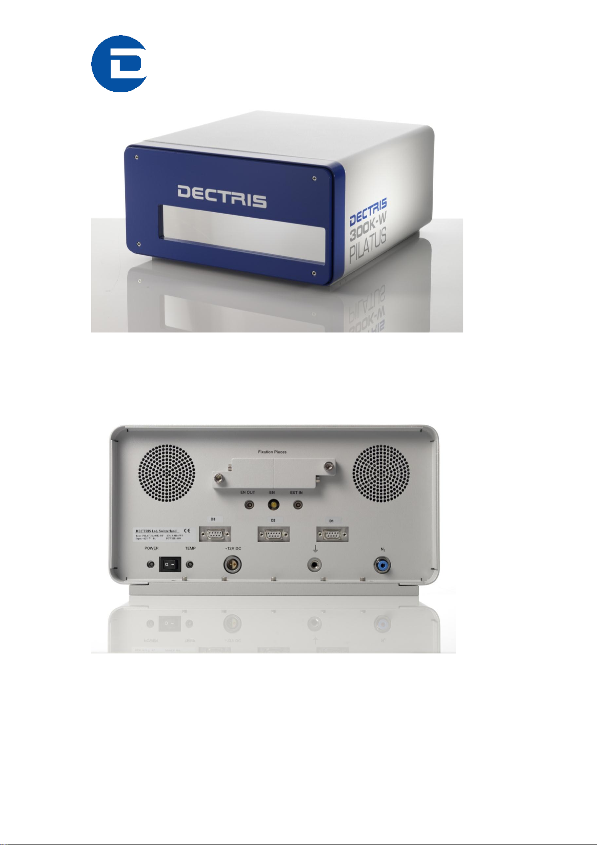
4.1.2 Backside of the Detector
Figure 4. PILATUS 300K-W detector viewed from the back
Technical_Specification_PILATUS_300K-W_V1_7 12/28
4.1.3 The Status LEDs
LED
Description
Power
If green, all supply voltages are ok.
If red, module power is off.
This can be caused by over/under temperature, too
much humidity or too high module current (One or more
modules may come into oscillations, see section 11).
Temp
Normally green. Turns red when the detector
temperature or humidity is out of the limits (see section
6).
EN
Yellow, detector is making an exposure.
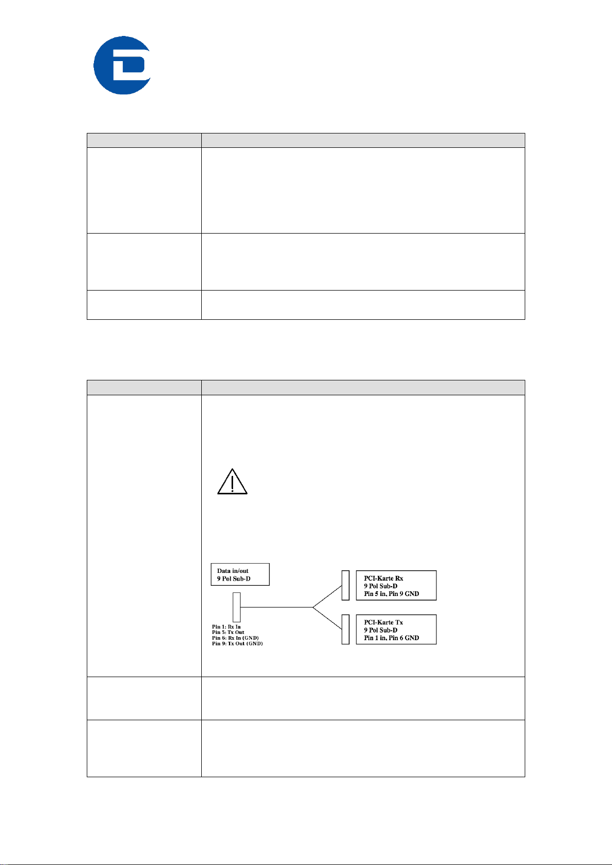
4.1.4 Connectors and Connecting Cables/Pipes
Connector
Description
DATA 1 (D1)
Data connection 1
Cable:
Use only the included cable. Custom made cables or
extensions will not work.
Minimum bending radius in a fix installation: 5
times the cable diameter. Minimum bending radius in a
flexible installation: 15 times the cable diameter.
Details of pins:
DATA 2 (D2)
Data connection 2 (fast option)
Follow the cabling rules of connection 1.
DATA 3 (D3)
Data connection 3 (fast option)
Follow the cabling rules of connection 1.
Technical_Specification_PILATUS_300K-W_V1_7 13/28
Connector
Description
Power +12 V
Main voltage 12 VDC from external power supply.
EXT IN
External Trigger Input
Use a Lemo ® Type 00 (NIM-CAMAC) cable.
For ratings see 3.1.
EN OUT
TTL output signal; high when counting is enabled.
Use a Lemo ® Type 00 (NIM-CAMAC) cable.
For ratings see 3.1.
Ground
Functional ground of the detector system.
Although the detector might be grounded via
the mounting bolts, the detector can be grounded
additionally via the functional ground connector at the
back (M6 screw-in tap hole) to establish a defined
grounding.
N2
Nitrogen for humidity control.
For details see section 5.3.
Pipe:
Use a pipe with outer diameter of 4 mm.
The fixation pieces and the transport hook are stored on the back of the
detector.

Technical_Specification_PILATUS_300K-W_V1_7 14/28
4.2 Power Supply
The power supply is a compact switching power unit with the dimensions
189 mm x 89.5 mm x 45.5 mm (length, width, height) and a weight of 800 g.
Figure 5. Power supply +12 V DC 130 W
Connector
Description
Main Inputs
90-260 V
max. 1.32 A
47-63 Hz
Output
12 V DC/ 10.8 A
Technical_Specification_PILATUS_300K-W_V1_7 15/28
4.3 Computer
The computer is a high power server with one (fast option: three) proprietary
data acquisition card(s) to communicate with the detector. Labels for the
connections are printed on the server housing.
The PC should be kept behind a firewall and should not have
outside internet access.
The operating system is optimized for high speed data acquisition
and has a custom kernel: Therefore, do not permit any software upgrades on
the kernel!
Do not install or run any other software on the computer, except as
tools and software necessary to configure your data acquisition protocol.
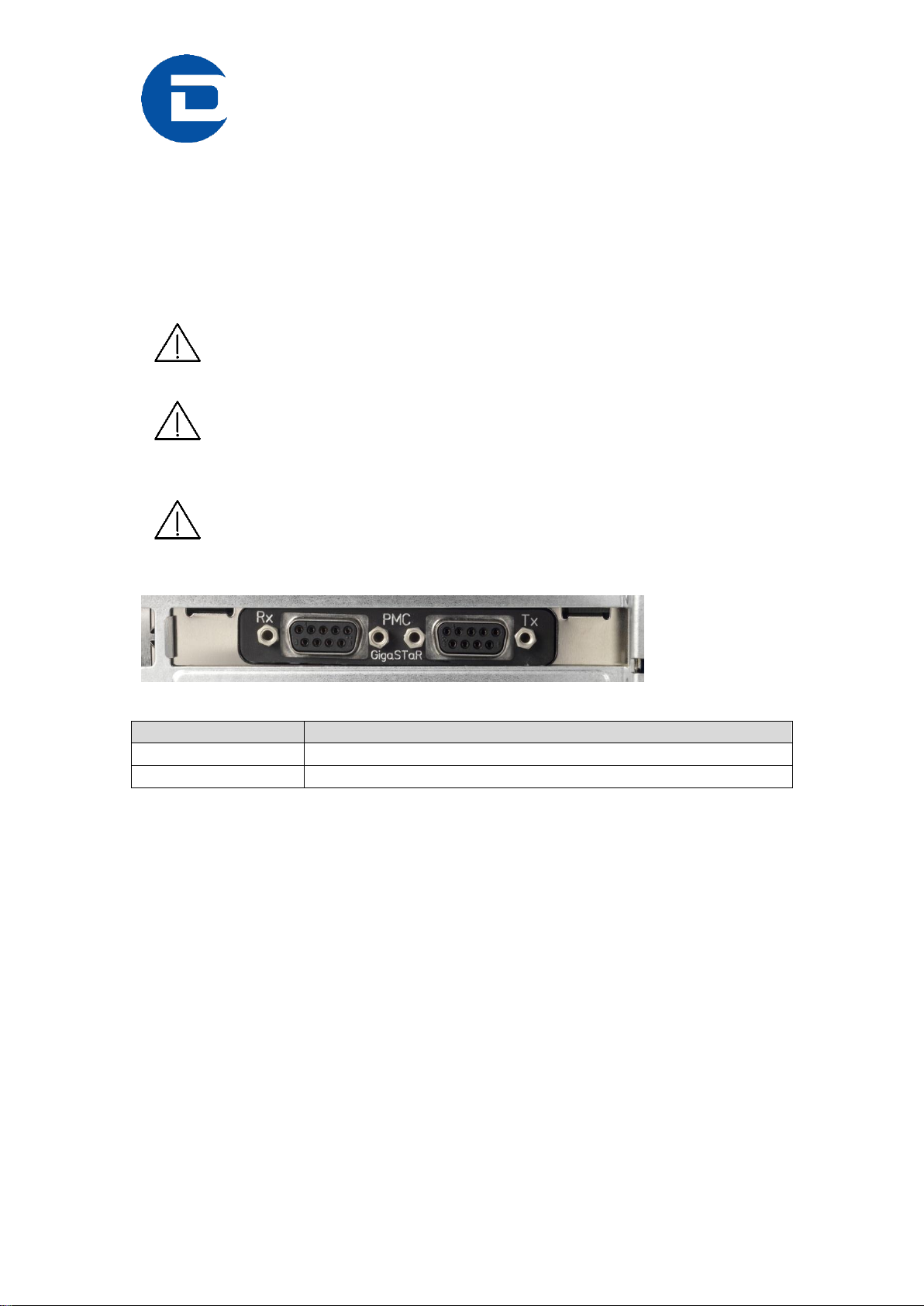
Figure 6. Connectors at the PCI Mezzanine Card for data acquisition
Connector
Description
RX
Receive data
TX
Transmit data

Technical_Specification_PILATUS_300K-W_V1_7 16/28
5 Installing the Detector System
5.1 Mounting
The detector can be mounted in two ways:
5.1.1 Mounting from Above
Use the detachable mounting pieces, which are stored on the back of the
detector. These mounting pieces have to be mounted on the base plate of the
detector.
Make sure the mounting pieces are mounted and properly
tightened.
Figure 7. Mounting from above, bottom view
Mounting points when mounting from the top
Technical_Specification_PILATUS_300K-W_V1_7 17/28
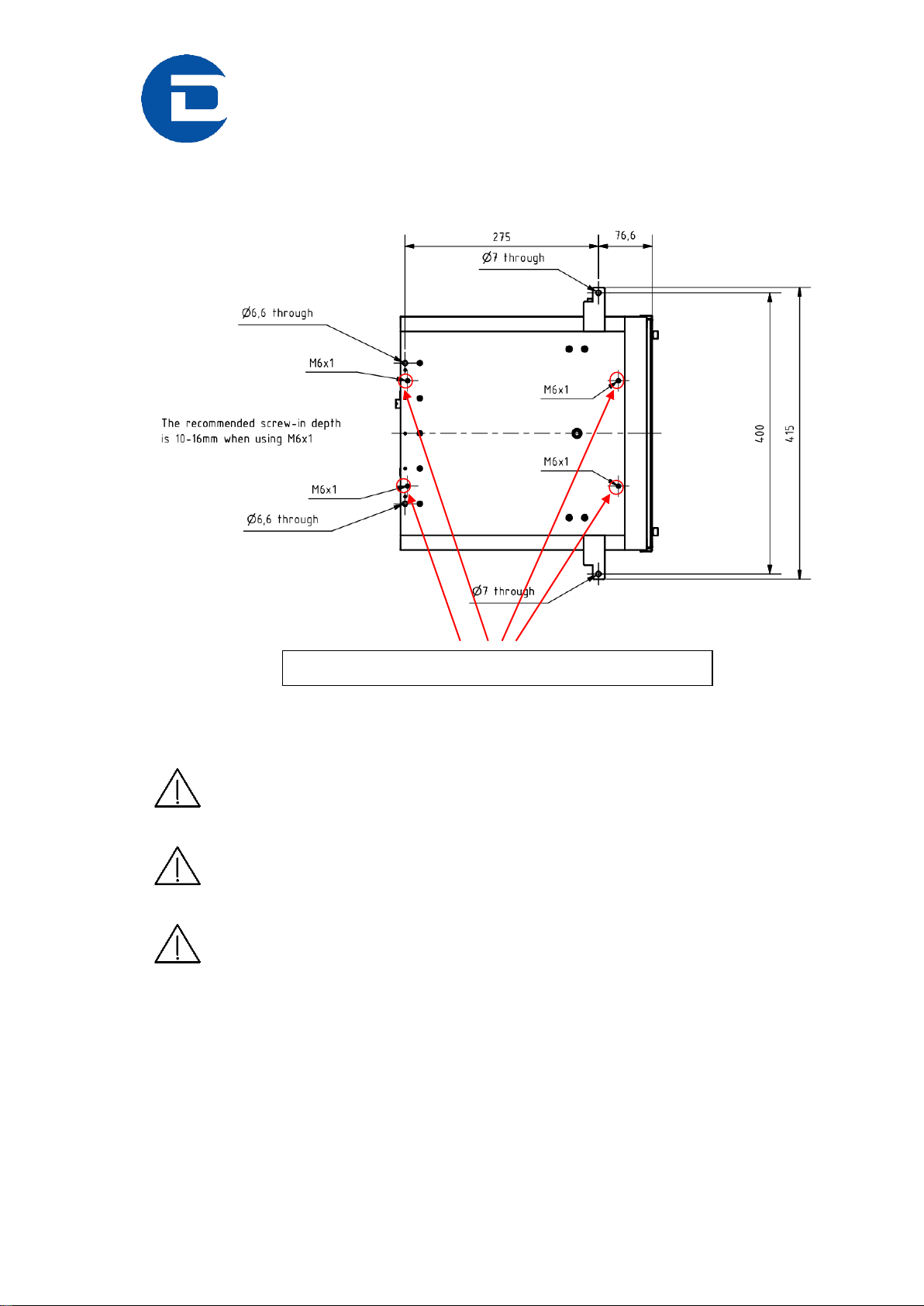
5.1.2 Mounting from Below
From below with four M6 bolts.
Figure 8. Mounting from below, bottom view
The four M6 bolts should not intrude into the detector more than 16
mm.
Make sure the detector is properly mounted.
Make sure the detector has enough space for proper ventilation
(minimum wall distance: 170 mm). Do not operate the detector in a closed
environment.
Mounting points when mounting from the bottom
Technical_Specification_PILATUS_300K-W_V1_7 18/28
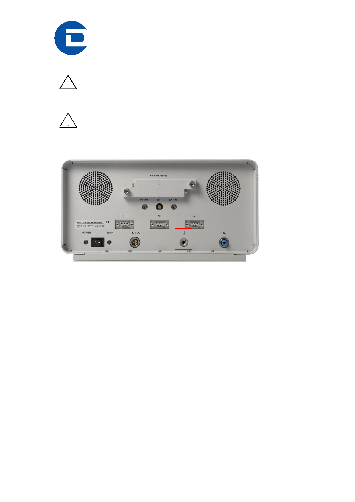
5.2 Grounding of the Detector System
The main plug of the computer and the power supply of the detector
have to be connected to a grounded power outlet.
Although the detector might be grounded via the mounting bolts,
the detector can be grounded additionally via the functional ground connector
at the back (M6 screw-in tap hole) to establish a defined grounding.
--
Figure 9. Ground connector on the back of the detector

Technical_Specification_PILATUS_300K-W_V1_7 19/28
5.3 Connection to Nitrogen or Dry Air
The PILATUS detector has to be connected to a nitrogen or dry air flow to
avoid humidity and condensation when it is outside the storage box. For
storage see section 9.
Figure 10. Nitrogen connector on the back of the detector
Humidity can damage the detector. Make sure that the detector is
operated in the specified range.
Recommended
flow of nitrogen
5-10 liter/h.
As alternative
Oil free, dry air of < 2% relative humidity can be used.
Recommended flow: 5-10 liter/h.
Gas pressure
Minimum 1 bar
Maximum 2 bar

Technical_Specification_PILATUS_300K-W_V1_7 20/28
5.4 Connecting the Cables
To operate the detector, the data cables and the ground should be connected.
For specification of cables and pipes see section 4.1.4.
The PILATUS 300K-W detector is equipped with one (fast option: three) data
cable(s).
Connect RX to RX and TX to TX on the GigaSTaR Card in the PC. Labels for
the connections are printed on the server housing. The single connectors go
to the corresponding connector on the back of the detector.
The data cable should be pulled onto the computer connectors with
the screws, rather than forcefully pushed on.
A forceful connection can damage the PCI card.
It is important for data integrity that the screws are tightened.
To plug or unplug any cables, turn the detector off.
Other manuals for PILATUS 300K-W
1
Table of contents
Other Dectris Laboratory Equipment manuals


Popular Laboratory Equipment manuals by other brands


Sartorius
Sartorius Centrisart G-26C operating manual

Santai Technologies
Santai Technologies SepaBean Hardware manual

Beckman Coulter
Beckman Coulter CytoFLEX Series Instructions for use

Hach
Hach 2100AN IS Basic user manual

Fluidigm
Fluidigm Juno Getting started guide

Panasonic
Panasonic NU-MX100P operating instructions