Dedrone RF-100 User manual

IM-Inst-RF100en v8.0 ENGLISH
INSTALLATIONS
Manual
RF-100

Dedrone
2v8.0 IM-Inst-RF100en
Legal Provisions
The information contained in these documents is the property of Dedrone GmbH. Any publication,
whether in whole or in part, requires prior written approval by Dedrone GmbH. Internal reproduc-
tion used solely for the purpose of product evaluation or other proper use is allowed and does not
require prior approval.
The declaration of conformity is available on request at support@dedrone.com.
Copyright
This manual is the intellectual property of Dedrone GmbH and is protected by copyright. All rights
reserved.
Dedrone GmbH
Miramstraße 87
34123 Kassel
Germany
Fon +49 561 861799-0
Fax +49 561 861799-111
Email info@dedrone.com
©2019 Dedrone GmbH. All rights reserved.
Dedrone Holding, Inc.
220 Sansome Street
San Francisco, CA 94104
USA
Fon +1 4145 913-6116
Email info@dedrone.com

IM-Inst-RF100en v8.0
Dedrone
3
Content
1 Safety ..............................................................................................................................................4
1.1 Symbols.................................................................................................................................................................4
1.2 Intended Use ........................................................................................................................................................4
1.3 Safety Information.............................................................................................................................................. 5
2 The RF-100 .....................................................................................................................................6
3 Unpacking....................................................................................................................................... 6
4 Scope of Delivery .......................................................................................................................... 7
5 Installation..................................................................................................................................... 7
5.1 Select the Mounting Place................................................................................................................................. 7
5.1.1 Mounting Location..................................................................................................................................... 7
5.1.2 Mounting Surface.......................................................................................................................................9
5.1.3 Mounting Orientation................................................................................................................................9
5.2 Power Supply and Required Tools ....................................................................................................................9
5.3 Cable Requirements and Preparation (Crimp)................................................................................................9
5.4 Install the sensor ............................................................................................................................................... 10
6 Integrate the RF-100 in your DroneTracker............................................................................ 12
6.1 Integrate the RF-100 in your on prem DroneTracker Server...................................................................... 12
6.2 Integrate the RF-100 via Dedrone Cloud ...................................................................................................... 13
7 Cleaning........................................................................................................................................ 14
8 Decommissioning ....................................................................................................................... 15
8.1 Shut down the RF-100...................................................................................................................................... 15
8.2 Dismantling ........................................................................................................................................................ 15
8.3 Disposal ............................................................................................................................................................... 15
9 Technical Data ............................................................................................................................. 16
Safety Dedrone
4v8.0 IM-Inst-RF100en
1 Safety
1.1 Symbols
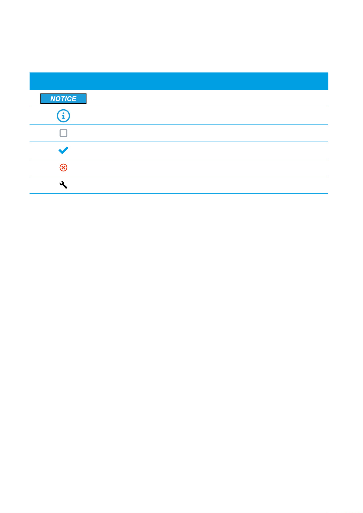
Symbol Explanation
Indicates a situation which, if not avoided, can result in property damage
Information that is important for a specific goal, but is not safety-rele-
vant
Indicates a requirement for meeting a specific goal
Desired result
A problem that might occur
Action to resolve a problem
1.2 Intended Use
The RF-100 is a passive, network-attached sensor for the detection of radio frequencies (RF). It sup-
plements the DroneTracker System with another level of detection. The RF-100 detects targeted
radio signals of different drones and remote controllers and sends the data, along with an alert, to
the DroneTracker System.
The RF-100 is intended for civil commercial and private use in conjunction with a DroneTracker
System.
The RF-100 is suitable for outdoor use.
Use this product only in accordance with the information provided in the enclosed documentation
and with the locally applicable legal standards and directives. Any other application may cause per-
sonal injury or property damage.
Any use of the product other than that described in the intended use section does not qualify as
appropriate. The enclosed documentation is an integral part of this product. Keep the documentati-
on in a convenient place for future reference and observe all instructions contained therein.
The type label must remain permanently attached to the product.
Compliance Information Statement FCC and IC
The RF-Sensor RF-100 complies with Industry Canada license-exempt RSS standard(s) and complies
with Part 15 of the FCC Rules. Operation is subject to the following two conditions:
1. This device may not cause harmful interference.
2. This device must accept any interference received, including interference that may cause
undesired operation.
Note: This equipment has been tested and found to comply with the limits for a Class A digital de-
vice, pursuant to part 15 of the FCC Rules. These limits are designed to provide reasonable protecti-

IM-Inst-RF100en v8.0
Dedrone
5
Safety
on against harmful interference when the equipment is operated in a commercial environment. This
equipment generates, uses, and can radiate radio frequency energy and, if not installed and used in
accordance with the instruction manual, may cause harmful interference to radio communications.
Operation of this equipment in a residential area is likely to cause harmful interference in which case
the user will be required to correct the interference at his own expense.
Modifications: Any modifications made to this device that are not approved by Dedrone GmbH may
void the authority granted to the user by the FCC to operate this equipment.
Caution!
To prevent permanent exposure, the device should be installed and operated with a
minimum distance of 20 cm (7.87 in) between the device and your body.
1.3 Safety Information
Read, follow and retain all of the following safety instructions. Heed all warnings on the unit and in
the operating instructions before operation.
Warning! Setup should be carried out by trained personnel only, in accordance with
the national electric code, ANSI/NSPA, and all local country codes.
Do not attempt to service this device yourself. Refer all servicing to qualified service
personnel. This device has no user-serviceable internal parts.
Whenever any damage to the device has occurred, unplug the devices from the power
source by disconnecting the patch cable and refer servicing to qualified service per-
sonnel. Such damages can be:
•the patch cable is damaged
•an object has fallen on the device
•the device has been dropped, or its enclosure has been damaged
•the device does not operate normally when the user follows the operating inst-
ructions correctly
Adjust only those controls specified in the operating instructions. Improper adjust-
ment of other controls may cause damage to the unit.
Despite careful construction, electrical devices can cause fires. Do not mount the
RF-100 in areas containing highly flammable materials or gases. Do not mount the
RF-100 in a potentially explosive atmosphere.
Do not install product near any heat sources such as radiators, heaters, exhaust air
systems or other equipment (including amplifiers) that produce heat.

The RF-100 Dedrone
6v8.0 IM-Inst-RF100en
Parts of the RF-100
AActivation button DRF pole mount
BRF-100 ENetwork socket (covered)
CAntenna
2 The RF-100
The RF-100 is a passive, network-attached sensor for the detection of radio frequencies (RF). The
RF-100 detects targeted radio signals of different drones and remote controllers and sends the
data, along with an alert, to the DroneTracker System.
E
D
C
B
A
It scans a wide frequency band for radio frequencies and classifies them. The data is recorded and
available on the DroneTracker user interface.
3 Unpacking
This equipment should be unpacked and handled with care. Check the exterior of the packaging for
visible damage. If an item appears to have been damaged in shipment, notify the shipper immedia-
tely.

IM-Inst-RF100en v8.0
Dedrone
7
Scope of Delivery
1 x RF-100
4 x Antenna (2x short, 2x long)
1 x RF pole mount (preassembled)
2 x Knurled head screw with sealing washer (preassembled)
2 x Knurled nut (preassembled)
2 x Strap
1 x Bag with 1x environmentally sealed Ethernet crimp connector, 1x RJ45 plug
1 x Installation manual
1 x Safety information (only US and Canada)
1 x Product registration document (this information is only needed for a cloud based sensor operation and is
provided by an enclosed document or online by the Dedrone Service)
The original packing carton is the safest container in which to transport the unit and must be used if
returning the unit for service. Save it for possible future use.
4 Scope of Delivery
Verify that all the parts listed in the scope of delivery are included. If any items are missing, notify
your Dedrone Partner.
Do not use this product if any component appears to be damaged. Please contact Dedrone in the
event of damaged goods.
5 Installation
5.1 Select the Mounting Place
5.1.1 Mounting Location
The position of the RF-100 has strong impact to the detection range. The RF-100 is designed for a
pole mounting. Make sure that a suitable pole is available (diameter between 1.6 in to 3.5 in (40 mm
to 90 mm)).
For ideal results the location should fulfill the following conditions:
`Clear view over the area
`elevated position: 10 ft (3 m) minimum, 33 ft (10 m) recommended
Select a secure installation location and mounting position for the RF-100. Ideally, this is a location
where the device cannot be interfered with, either intentionally or accidentally.

Installation Dedrone
8v8.0 IM-Inst-RF100en
Note the properties of each RF-100. This is needed for the correct configuration and
for service.
We recommend the table below. The following information is important:
•Serial Number (see product plate)
•GPS-position in degree (longitude and latitude)
Serial number
(see prouct plate)
GPS position
(in degree, e.g. 52.516295, 13.377653)
longitude:
latitude:
longitude:
latitude:
Overvoltage Protection
For safe mounting in an exposed position overvoltage protection must be observed.
Ensure that the pole is connected to the lightning conductor of the building. The RF-100 itself must
not be grounded directly. The lightning conductor must be installed at least 5 ft (1.5 m) above the
RF-100.
Lightning Protection Installation with RF-100s
Do not install the device near the following objects:
•Walls because these shades the detection area and prevent classification of signals behind the
wall
•Any excessive heat sources
•Any overhead power lines, power circuits, high-voltage lines or electrical lights, or where there
is a chance of electrical discharge
•Behind metal surfaces or vaporized glass because this could reduce the detection range
Ensure that the location has the appropriate clearance from power and lightning conductors, in
accordance with NEC725 and NEC800 (CEC Rule 16-224 and CEC Section 60).

IM-Inst-RF100en v8.0
Dedrone
9
Installation
5.1.2 Mounting Surface
Make sure the selected mounting surface is capable of supporting the combined weight of the
RF-100 (8 lb (3.6 kg)) and pole under all expected conditions of load, vibration, and temperature.
5.1.3 Mounting Orientation
The orientation of the device itself does not have any effect for the performance. Important for a
good result is the orientation of the antenna. Both antennas must orientated skywards.
5.2 Power Supply and Required Tools
Power Supply
The RF-100 does not need any additional power supply connection. The power supply is provided by
the connected switch with activated active PoE+ (802.3at).
`Make sure, that your network has activated active PoE+ (802.3at).
Note: Data transfer is only possible with a suitable PoE switch.
Required Tools
`Socket wrench: 7 mm ( 9/32” )
`Crimping tool
For an environmentally sealed connection to the RF-100, it's necessary to crimp the supplied
connector to the laid patch cable (see Cable Preparation, page 10).
`Ladder or lift truck, depending on the mounting location
`Recommendation: GPS device
5.3 Cable Requirements and Preparation (Crimp)
Cable Requirements
Type Cat-6 Patch Cable
Recommendation: Cat-7 Patch Cable
Maximum Length 328 ft (100 m)
For longer distances a PoE extender is required
External Diameter 3.5 mm – 7.5 mm
Installation Dedrone
10 v8.0 IM-Inst-RF100en
Cable Preparation
For a weather resistant connection to the RF-100, it is necessary to crimp the supplied environmen-
tally sealed Ethernet connector to the patch cable.
Procdure:
1 Cut the RJ45 plug off the laid cable. Keep the cut off plug, to check the wiring standard
later.
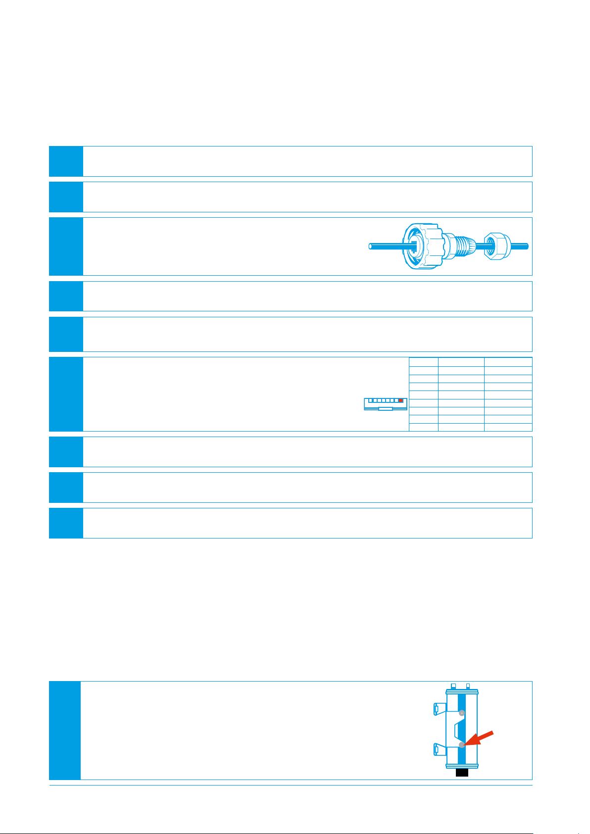
2 Screw the gland off the connector body.
3 Thread the gland nut and the connector body onto the
cable.
4 Remove the cable jacket carefully. Therefore, take care not to damage the braid and foil.
5 Fold back the braid and foil over the cable jacket.
Note: 25 mm (1”) of free conductors are needed.
6 Unravel the conductors, sort the conductors in the re-
quired wiring standard (568-A or 568-B), and push the
conductors all the way in the plug.
The required wiring standard can be checked on the
previous cut-off RJ45 plug.
7 Crimp the RJ45 plug with the crimping tool.
8 Push down the latching clip of the plug and press the connector body all the way to the
stop over the RJ45 plug.
9 Put the gland nut over the connector body and screw down the gland nut on the connec-
tor body.
Position 568-A 568-B
White/Green White/Orange
2 Green Orange
3 White/Orange White/Green
4 Blue Blue
5 White/Blue White/Blue
6 Orange Green
7 White/Brown White/Brown
8 Brown Brown
1
Front face view
5.4 Install the sensor
Requirements:
`Desired mounting place fulfills the requirements (see 5.1 Select the Mounting Place, page 7)
`Diameter of the pole: between 1.6 in to 3.5 in (40 mm to 90 mm)
Procdure:
1 Loosen the knurled head screws with the sealing washers
on both sides of the RF-100 and unhook the RF-100 from
the RF pole mount.
IM-Inst-RF100en v8.0
Dedrone
11
Installation
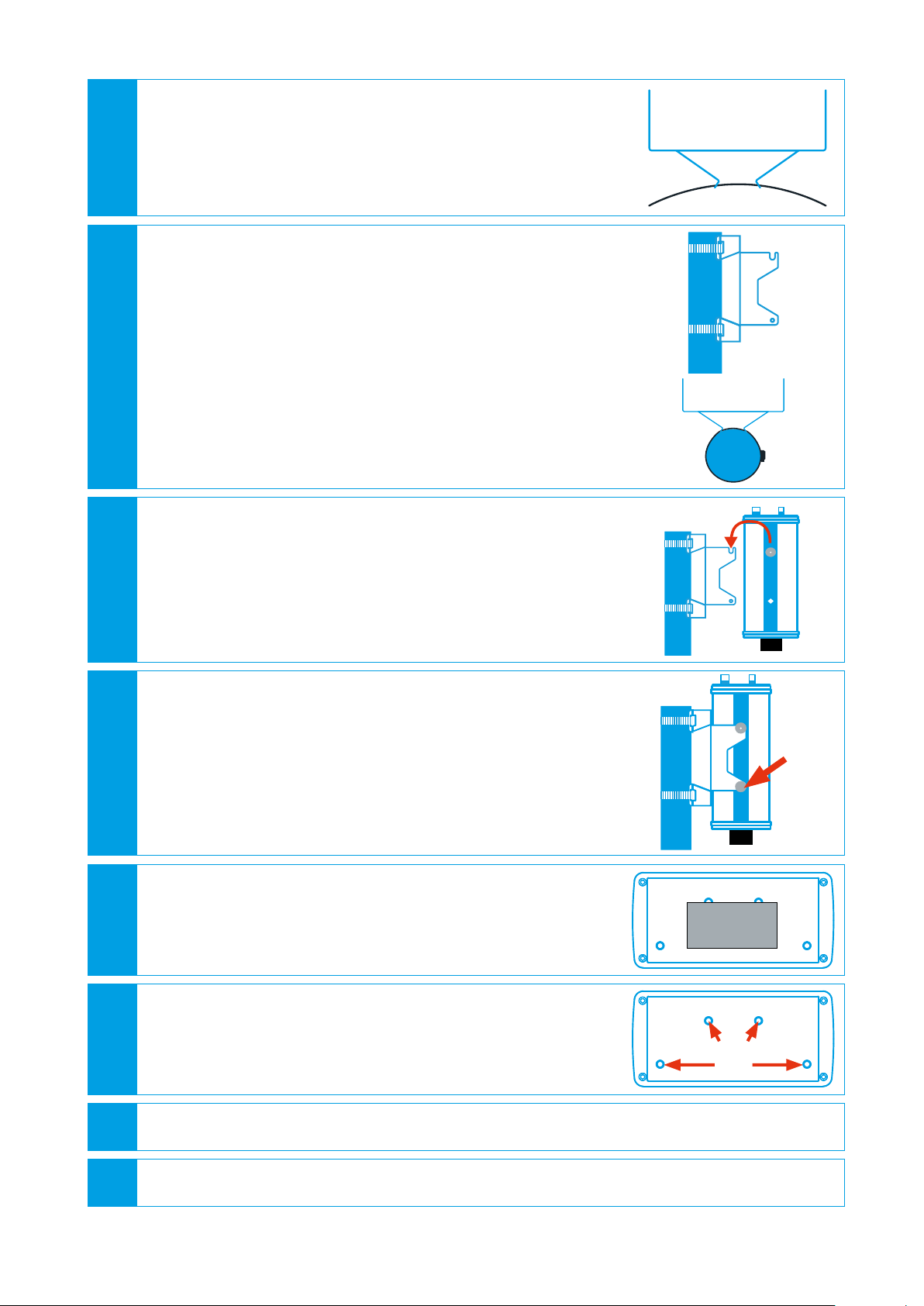
2 Run the straps through the slashes of the RF pole mount.
3 Mount the the Pole Mount to the pole:
•Hold the RF pole mount at the desired height of the pole.
•Lay the straps around the pole.
•Put the strap in the slash under the screw and tighten it
with the socket wrench 7 mm ( 9/32” ) appropriately.
4 Hook the RF-100 in the screw guidance of the RF pole
mount.
5 Screw down the 2 knurled head screws with the sealing
washers at both sides in the lower holes.
•Make sure that the soft side of the sealing washer is faced
to the RF pole mount.
•Tighten the screws carefully. The RF pole mount should
not be bent.
6 If a GPS device is available, place it on top of the RF-100 and
note the longitude and latitude in the table (see 5.1.1 Moun-
ting Location, page 7).
7 Screw the antennas on the screw threads at the top of the
RF-100.
Therefore, note the correct positioning of the short and long
antenna.
8 Adjust the antenna of the RF-100 skywards.
9 Make sure that the pole is grounded (see Overvoltage Protection, page 8).
GPS device
short
long
Integrate the RF-100 in your DroneTracker Dedrone
12 v8.0 IM-Inst-RF100en
10 Connect the patch cable to the RF-100 and turn the connector gland until it is locked (for
a correct cable preparation see 5.3 Cable Requirements and Preparation (Crimp), page
9).
]If the patch cable is connected to the network, the RF-100 boots automatically and af-
ter approximately 1 second the activation button at the RF-100 illuminates, indicating
that the hardware is ready.
\The patch cable is connected to the network and the RF-100 does not boot automati-
cally after approximately 1 second?
EPush the blue button and wait for it to illuminate.
EMake sure that active PoE+ (802.3at) is activated in your network.
6 Integrate the RF-100 in your DroneTracker
The integration procedure of the RF-100 in your DroneTracker depends on the system type:
•On premises installations use your local DroneTracker Server (see 6.1 Integrate the RF-100 in
your on premises DroneTracker Server, page 12).
•Dedrone Cloud installations do not require any additional infrastructure and are connected to
the Dedrone Cloud (see 6.2 Integrate the RF-100 via Dedrone Cloud, page 13).
6.1 Integrate the RF-100 in your on premises DroneTracker Server
To connect to the RF-100 DHCP-Services are required that automatically assign an IP address to
the RF-100. If the RF-100 and the DroneTracker Server are in the same Layer2 network they can be
connected directly. If the RF-100 and the DroneTracker Server are in different networks refer to the
Dedrone Planning Manual or consult your network administrator.
Requirements:
`RF-100 is installed.
`The power supply is working and the button at the RF-100 illuminates blue.
`RF-100 is connected to the network.
`The IP address of the DroneTracker Server is known.
Procedure:
1 Start your web-browser and enter the address of your DroneTracker Server.
For an optimal use, Dedrone recommends Chrome or Firefox.
2 Log in the DroneTracker user interface as an administrator or configurator. The default
login credentials are:
User: admin Password: dedrone
]The DroneTracker user interface appears.
3 Choose OPTIONS > Site Configuration.

IM-Inst-RF100en v8.0
Dedrone
13
Integrate the RF-100 in your DroneTracker
4 Choose [Add] > Dedrone RF Sensor.
]The window Discovered Sensors appears.
5 Select the desired RF-100 and choose [OK].
]The RF-100 appears in the Site Explorer.
6 To sort the RF-100 in the Site Explorer, drag and drop the element to the desired position.
7 Choose [Save changes].
]The window Site Configuration disappears.
8 Choose OPTIONS > Map Editor.
9 Choose [Add] > Sensor.
Choose the desired RF-100 in the window Select sensor.
Choose [OK].
]The RF symbol appears on the map.
10 Move the RF symbol per drag and drop on the installation position on the map.
If the sensor was installed and aligned with a GPS device enter the noted values in the
fields Longitude and Longitude.
11 To lock the settings activate the option Lock settings.
12 Choose [Save changes].
]The window Map Editor disappears.
For further information consult chapter “First Steps” of the integrated online help in the
DroneTacker UI.
6.2 Integrate the RF-100 via Dedrone Cloud
Requirements:
`RF-100 is installed.
`The power supply is working and the button at the RF-100 illuminates blue.
`RF-100 is connected to the Dedrone Cloud.
`The address of your Dedrone Cloud access is known (provided by Dedrone).
`The registration key of the sensor is available (provided by Dedrone).

Cleaning Dedrone
14 v8.0 IM-Inst-RF100en
1 Start your web-browser and enter the address of your Dedrone Cloud.
For an optimal use, Dedrone recommends Chrome or Firefox.
2 Log in the DroneTracker UI as an administrator or configurator.
3 Choose OPTIONS > Site Configuration.
4 Choose [Add] > Register device.
]The window Register device appears.
5 Enter the registration key of your sensor and choose [OK].
]The RF-100 appears in the Site Explorer.
6 To sort the RF-100 in the Site Explorer, drag and drop the element to the desired position.
7 Choose [Save changes].
]The window Site Configuration disappears.
8 Choose OPTIONS > Map Editor and choose the RF-100.
9 Choose [Add] > Sensor.
Choose the desired RF-100 in the window Select sensor.
Choose [OK].
]The RF symbol appears on the map.
10 Move the RF symbol per drag and drop on the installation position on the map.
If the sensor was installed and aligned with a GPS device enter the noted values in the
fields Longitude and Longitude.
11 To lock the settings, choose the option Lock settings.
12 Choose [Save changes].
]The window Map Editor disappears.
For further information consult chapter “First Steps” of the integrated online help in the
DroneTacker UI.
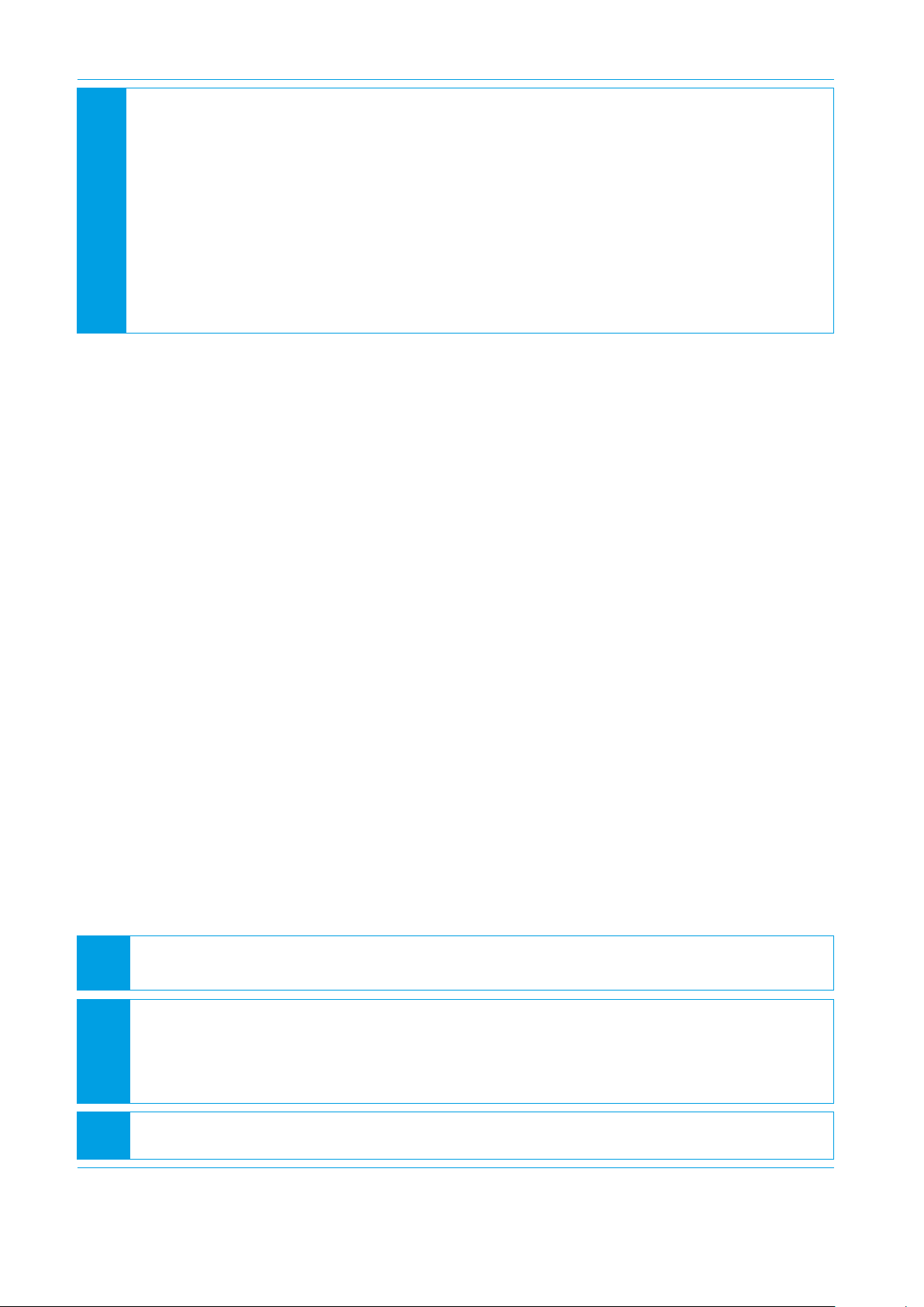
7 Cleaning
Wrong cleaner damages the housing
The wrong cleaner can damage the housing or antenna of the RF-100. Never use glass cleaner or
other solvent cleaner to clean the RF-100.
•Use solvent-free cleaner to clean the RF-100.
Procedure:

IM-Inst-RF100en v8.0
Dedrone
15
Decommissioning
8 Decommissioning
8.1 Shut down the RF-100
RF-100 breaks
By disconnecting the cable without shut down the RF-100, the RF-100 could break.
•Always shut down the RF-100 before disconnecting the cable.
You have the option to shut down the RF-100 via the DroneTracker user interface or directly on the
sensor.
Shut down via DroneTracker user interface:
1 Log in to the DroneTracker UI.
2 Choose OPTIONS > Site Configuration.
3 Right-click on the desired RF-100.
4 Choose System > Shutdown hardware.
Briefly press the activation button at the RF-100.
]The RF-100 shuts down and the blue light goes out.
Shut down directly at the RF-100:
8.2 Dismantling
8.3 Disposal
Hot surface during operation
Depending on the evironment the surface of the RF-100 could get hot.
•Before dismantling the device wait 30 min after shut down the RF-100.
Dispose the RF-100 at the end of its service life in accordance with the disposal regu-
lations for electronic waste which apply at the installation location at that time. Al-
ternatively, send it back to Dedrone GmbH with shipping paid by sender, and labeled
"ZUR ENTSORGUNG" ("FOR DISPOSAL").

Technical Data Dedrone
16 v8.0 IM-Inst-RF100en
Range (line of sight) 0.65 mi (1.0 km)
In ideal conditions up to 1.3 mi (2 km)
Radio Frequency Omnidirectional passive detection and classification
L x W x H 7.7” x 3.7” x 17.3” (195 mm x 95 mm x 440 mm)
height without antenna: 9.8” (250 mm)
Weight (including mounting) 8 lb (3.6 kg)
Ingress Protection Rating IP65 *
Operating Temperature -4 °F to +122 °F (-20 °C to +50 °C)
Power Supply Active PoE+ (IEEE 802.3at)
Power Consumption 15 W (typ.)
Connectivity Via LAN to existing IT infrastructure or via the
Dedrone Cloud
Configuration, Operation, and
Alarms
Via DroneTracker software (software version >= 3.1 and valid
license)
Software Updates Firmware and DroneDNA updates via cloud-based
connection
9 Technical Data
* No ingress of dust; complete protection against contact (dust tight). Water projected by a nozzle (6.3 mm) against
enclosure from any direction shall have no harmful effects.

IM-Inst-RF100en v8.0
Dedrone
17
Notes

Dedrone
18 v8.0 IM-Inst-RF100en
Notes

IM-Inst-RF100en v8.0
Dedrone
19
Notes
AIRSPACE
SECURITY
SOLUTION
+
+
www.dedrone.com
Dedrone GmbH
Miramstraße 87
34123 Kassel
Germany
Dedrone Holding, Inc.
220 Sansome Street
San Francisco, CA 94104
USA
Other manuals for RF-100
1
Table of contents
Other Dedrone Accessories manuals


