Dedrone RF-160 User manual

IM-Inst-RF160en v0.4 ENGLISH
INSTALLATION
Manual
RF-160

Dedrone
2v0.4 IM-Inst-RF160en
Legal Provisions
The information contained in these documents is the property of Dedrone GmbH. Any publication,
whether in whole or in part, requires prior written approval by Dedrone GmbH. Internal reproduc-
tion used solely for the purpose of product evaluation or other proper use is allowed and does not
require prior approval.
The declaration of conformity is available on request at support@dedrone.com.
Copyright
This manual is the intellectual property of Dedrone GmbH and is protected by copyright. All rights
reserved.
Dedrone GmbH
Miramstraße 87
34123 Kassel
Germany
Fon +49 561 861799-0
Fax +49 561 861799-111
Email info@dedrone.com
©2019 Dedrone GmbH. All rights reserved.
Dedrone Holding, Inc.
220 Sansome Street
San Francisco, CA 94104
USA
Fon +1 4145 913-6116
Email info@dedrone.com

IM-Inst-RF160en v0.4
Dedrone
3
Content
1 Safety ..............................................................................................................................................4
1.1 Symbols.................................................................................................................................................................4
1.2 Intended Use ........................................................................................................................................................4
1.3 Safety Information.............................................................................................................................................. 5
2 The RF-160 .....................................................................................................................................6
3 Unpacking....................................................................................................................................... 6
4 Scope of Delivery .......................................................................................................................... 7
5 Select the Mounting Place .......................................................................................................... 7
5.1 Detection Conditions.......................................................................................................................................... 7
5.2 Overvoltage Protection .....................................................................................................................................8
6 Installation..................................................................................................................................... 9
6.1 Power Supply .......................................................................................................................................................9
6.2 Cable Requirements............................................................................................................................................9
6.3 Cable Preparation for LAN connection............................................................................................................9
6.4 Install the Sensor...............................................................................................................................................10
7 Integrate the RF-160 in your DroneTracker............................................................................ 13
7.1 Integrate the RF-160 in your on prem DroneTracker Server...................................................................... 13
7.2 Integrate the RF-160 via Dedrone Cloud ...................................................................................................... 15
8 Cleaning........................................................................................................................................ 16
9 Decommissioning ....................................................................................................................... 16
9.1 Shut down the RF-160...................................................................................................................................... 16
9.2 Dismantling ........................................................................................................................................................ 16
9.3 Disposal ............................................................................................................................................................... 16
10 Technical Data ..............................................................................................................................17
Safety Dedrone
4v0.4 IM-Inst-RF160en
1 Safety
1.1 Symbols
Symbol Explanation
Indicates a situation which, if not avoided, can result in property
damage
Information that is important for a specific goal, but is not
safety-relevant
Indicates a requirement for meeting a specific goal
Desired result
A problem that might occur
Action to resolve a problem
1.2 Intended Use
The RF-160 is a passive, network-attached sensor for the detection of radio frequencies (RF). The
RF-160 detects targeted radio signals of different drones and remote controllers and sends the
data via mobile data or local network connection, along with an alert to the DroneTracker System.
The RF-160 is intended for civil commercial and private use in conjunction with a DroneTracker
System.
The RF-160 is suitable for outdoor use.
Use this product only in accordance with the information provided in the enclosed documentation
and with the locally applicable legal standards and directives. Any other application may cause per-
sonal injury or property damage.
Any use of the product other than that described in the intended use section does not qualify as
appropriate. The enclosed documentation is an integral part of this product. Keep the documentati-
on in a convenient place for future reference and observe all instructions contained therein.
The type label must remain permanently attached to the product.
Compliance Information Statement FCC and IC
The RF-Sensor RF-160 complies with Industry Canada license-exempt RSS standard(s) and complies
with Part 15 of the FCC Rules. Operation is subject to the following two conditions:
1. This device may not cause harmful interference.
2. This device must accept any interference received, including interference that may cause
undesired operation.
Note: This equipment has been tested and found to comply with the limits for a Class B digital de-
vice, pursuant to Part 15 of the FCC Rules. These limits are designed to provide reasonable protecti-
on against harmful interference in a residential installation. This equipment generates, uses and can
radiate radio frequency energy and, if not installed and used in accordance with the instructions,
IM-Inst-RF160en v0.4
Dedrone
5
Safety
may cause harmful interference to radio communications. However, there is no guarantee that
interference will not occur in a particular installation. If this equipment does cause harmful inter-
ference to radio or television reception, which can be determined by turning the equipment off and
on, the user is encouraged to try to correct the interference by one or more of the following measu-
res:
•Reorient or relocate the receiving antenna.
•Increase the separation between the equipment and receiver.
•Connect the equipment into an outlet on a circuit different from that to which the receiver is
connected.
•Consult the dealer or an experienced radio/television technician for help.
Modifications: Any modifications made to this device that are not approved by Dedrone GmbH may
void the authority granted to the user by the FCC to operate this equipment.
Caution!
To prevent permanent exposure, the device should be installed and operated with a
minimum distance of 20 cm (7.87 in) between the device and your body.
1.3 Safety Information
Read, follow and retain all of the following safety instructions. Heed all warnings on the unit and in
the operating instructions before operation.
Warning! Setup should be carried out by trained personnel only, in accordance with the
national electric code, ANSI/NSPA, and all local country codes.
Danger of life due to electric shock.
Whenever any damage to the device has occurred live components could be touched,
which can lead to lethal electric shocks. Such damages can be:
•the AC cable is damaged
•the patch cable is damaged
•an object has fallen on the device
•the device has been dropped, or its enclosure has been damaged
•the device does not operate normally when the user follows the operating instruc-
tions correctly
When the RF-160 is plugged into an AC power source, there is always voltage applied to
the internal electronics. Unplug the devices from the power source by disconnecting the
AC cable and patch cable immediately. Make sure, that the power socket is always acces-
sible.
Refer all servicing to qualified service personnel. This device has no user-serviceable
internal parts. Do not attempt to service this device yourself.
Adjust only those controls specified in the operating instructions. Improper adjustment
of other controls may cause damage to the unit.
The RF-160 Dedrone
6v0.4 IM-Inst-RF160en
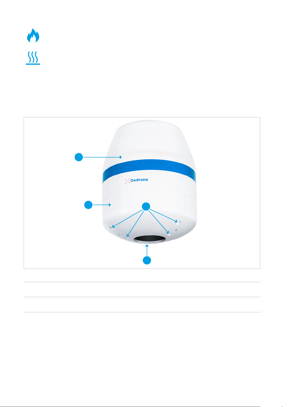
Parts of the RF-160
ARF-160 CCover screw
BCover DGrip recess and activation button
2 The RF-160
The RF-160 is a passive, network-attached sensor for the detection of radio frequencies (RF). The
RF-160 detects targeted radio signals of different drones and remote controllers and sends the
data via mobile data or local network connection, along with an alert to the DroneTracker System.
It scans a wide frequency band for radio frequencies and classifies them. The data is recorded and
available on the user interface DroneTracker UI.
3 Unpacking
This equipment should be unpacked and handled with care. Check the exterior of the packaging for
visible damage. If an item appears to have been damaged in shipment, notify the shipper immedia-
tely.
BC
A
D
Despite careful construction, electrical devices can cause fires. Do not mount the RF-160
in areas containing highly flammable materials or gases. Do not mount the RF-160 in a
potentially explosive atmosphere.
Do not install product near any heat sources such as radiators, heaters, exhaust air sys-
tems or other equipment (including amplifiers) that produce heat.

IM-Inst-RF160en v0.4
Dedrone
7
Scope of Delivery
1 x RF-160
1 x Screwdriver
1 x AC cable with outdoor plug, 16 ft. (5 m)
1 x Outdoor ethernet cable, 32 ft. (10 m)
1 x Bag with the 5 parts of the outdoor housing for prewired RJ45 cordset and a quick manual
1 x Fall protection ring
1 x Installation manual
1 x Safety information
1 x Product registration document (this information is only needed for a cloud based sensor operation and is
provided by an enclosed document or online by the Dedrone Service)
The original packing carton is the safest container in which to transport the unit and must be used if
returning the unit for service. Save it for possible future use.
4 Scope of Delivery
Verify that all the parts listed in the scope of delivery are included. If any items are missing, notify
your Dedrone Partner.
Do not use this product if any component appears to be damaged. Please contact Dedrone in the
event of damaged goods.
5 Select the Mounting Place
The position of the RF-160 has strong impact to the detection range. The RF-160 is intended for an
installation on top of a pole. Make sure that a suitable pole is available (diameter between 1.2 in to
3.1 in (40 mm to 80 mm)).
5.1 Detection Conditions
For ideal results the location should fulfill the following conditions:
`Clear view over the area
`Exposed, elevated position (minimum 10 ft (3 m))
Do not install the device nearby the following objects:
•Metal surfaces or vaporized glass
Disturbs the detection.
•Walls
These share the detection area and prevent classification of signals behind the wall.
•Base station and other strong signale sources
Select the Mounting Place Dedrone
8v0.4 IM-Inst-RF160en
The detected signals are getting interfered.
•Any excessive heat sources
•Any overhead power lines, power circuits, or electrical lights
Electrical discharge can damage the device.
Select a secure installation location and mounting position for the device. Ideally, this is a location
where the device cannot be interfered with, either intentionally or accidentally.Mounting Location
Mounting Surface
•Make sure the selected mounting surface is capable of supporting the combined weight of the
RF-160 (12.2 lb (5.5 kg)) and the pole under all expected conditions of load, vibration, and tem-
perature.
Mounting Orientation
•Important for a good result is the vertical alignment of the device. Do not tilt the device.
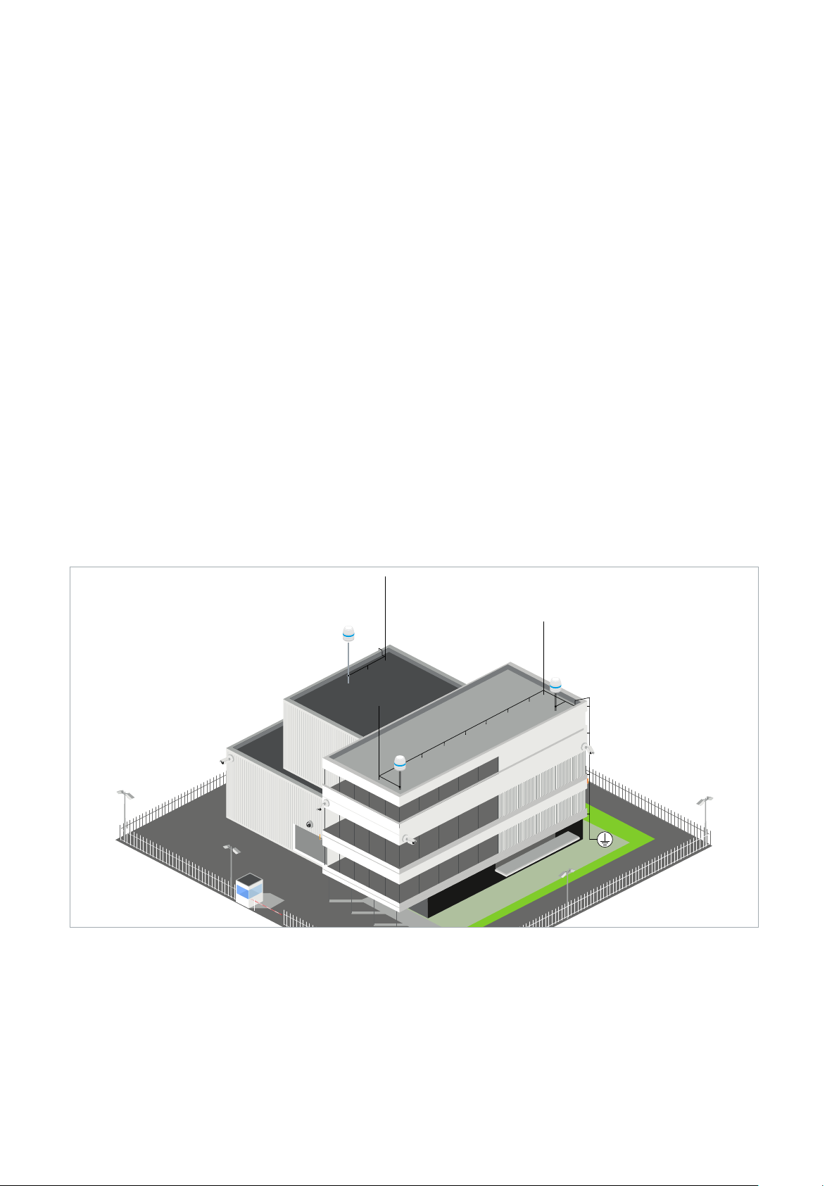
5.2 Overvoltage Protection
For safe mounting in an exposed position overvoltage protection must be observed.
Ensure that the mast is connected to the lightning conductor of the building and there is a metallic
contact between the mast mount and the mast. The lightning conductor must be installed at least
1.5 m above the RF-160.
Lightning Protection Installation with RF-160s
Ensure that the location has the appropriate clearance from power and lightning conductors, in
accordance with NEC725 and NEC800 (CEC Rule 16-224 and CEC Section 60 and Section 810 of the
National Electrical Code, ANSI/NFPA No.70).

IM-Inst-RF160en v0.4
Dedrone
9
Installation
6 Installation
6.1 Power Supply
The RF-160 can use two kinds of power supplies:
•AC power supply with the supplied power plug via a socket (AC 100-240V 50/60 Hz).
`Make sure that the power socket is grounded.
`In Denmark: Apparatets stikprop skal tilsluttes en stikkontakt med jord som giver forbindel-
se til stikproppens jord.
`In Finland: Laite on liitettävä suojakoskettimilla varustettuun pistorasiaan.
`In Norway: Apparatet må tilkoples jordet stikkontakt.
`In Sweden: Apparaten skall anslutas till jordat uttag
•Power over Ethernet via the supplied patch cable.
`Make sure, that your network has activated active PoE+ (802.3at).
6.2 Cable Requirements
To connect the sensor with another cable as the supplied, note the following requirements.
Type Cat-6 patch cable, shielded, suitable for outdoor use
Recommendation: Cat-7 patch pable, shielded, suitable for
outdoor use
Maximum Length 328 ft (100 m)
For longer distances a PoE extender is required
External Diameter 3.5 mm – 7.5 mm
1 Put the gland nut onto the cable. Thereby
make sure that the thread shows to the plug.
2 •Open the sleeve and close it around the
cable. Thereby make sure that the closer
ring shows to the gland.
•Put the sealing ring and the plastic ring
over the cable. Thereby make sure that
the sequence of the elements is correct.
6.3 Cable Preparation for LAN connection
For a weather resistant connection to the RF-160, it is necessary to put on the supplied outdoor
housing to the prewired RJ45 cordset.
Procedure:

Installation Dedrone
10 v0.4 IM-Inst-RF160en
6.4 Install the Sensor
`Desired mounting place fulfills the requirements (see chapter 5 Select the Mounting Place,
page 7).
`Diameter of the pole: between 1.2 in to 3.1 in (40 mm to 80 mm)
Procedure:
3 Thread the connector body over the plug.
]The plug clicks in and gets fixed in the
connector body.
4 Slide the gland to the connector body and
screw down the gland nut on the connector
body.
1 Open the carton, remove the upper foam.
2 Open the cover:
•Stuck the supplied tool in the slot bet-
ween the cover screws.
•Gently pry the cover on both sides.
]The cover comes up a little bit.
3 Remove the cover and put it aside.
4 Loosen both fixing screws and the security
screw.
You do not need to unscrew the screws
completely.

IM-Inst-RF160en v0.4
Dedrone
11
Installation
5 Take out the pole mount.
6 Put the pole mount on the pole.
•To open up the pole mount unscrew the
pole fixing screws.
7 Adjust the pole mount in the desired directi-
on and tighten the pole fixing screws approp-
riately. Only use the supplied screws.
8 Center the pole mount plate over the pole
and tighten the aligning screws appropria-
tely. Only use the supplied screws.
9 If fall protection according to the installati-
on regulations is required screw down the
supplied fall protection ring and connect your
suitable fall protection to the ring.
The fall protection must be dimensioned
according to installation height in terms of
thickness and length.

Installation Dedrone
12 v0.4 IM-Inst-RF160en
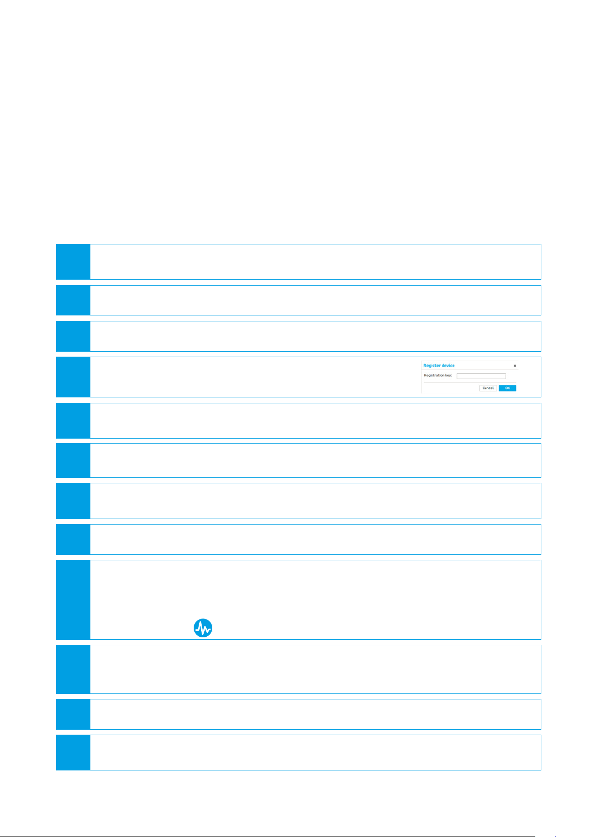
10 Place the RF-160 on the pole mount
•Slide the fixing screws in the screw guides
of the mounting plate (1). Thereby make
sure that the two flaps of the pole mount
slides in the slot of the RF-160.
•Tighten the security screw by hand (2).
Thereby the sensor is secured from falling
down. 1
2
•Tighten the fixing screws appropriately.
Only use the supplied screws.
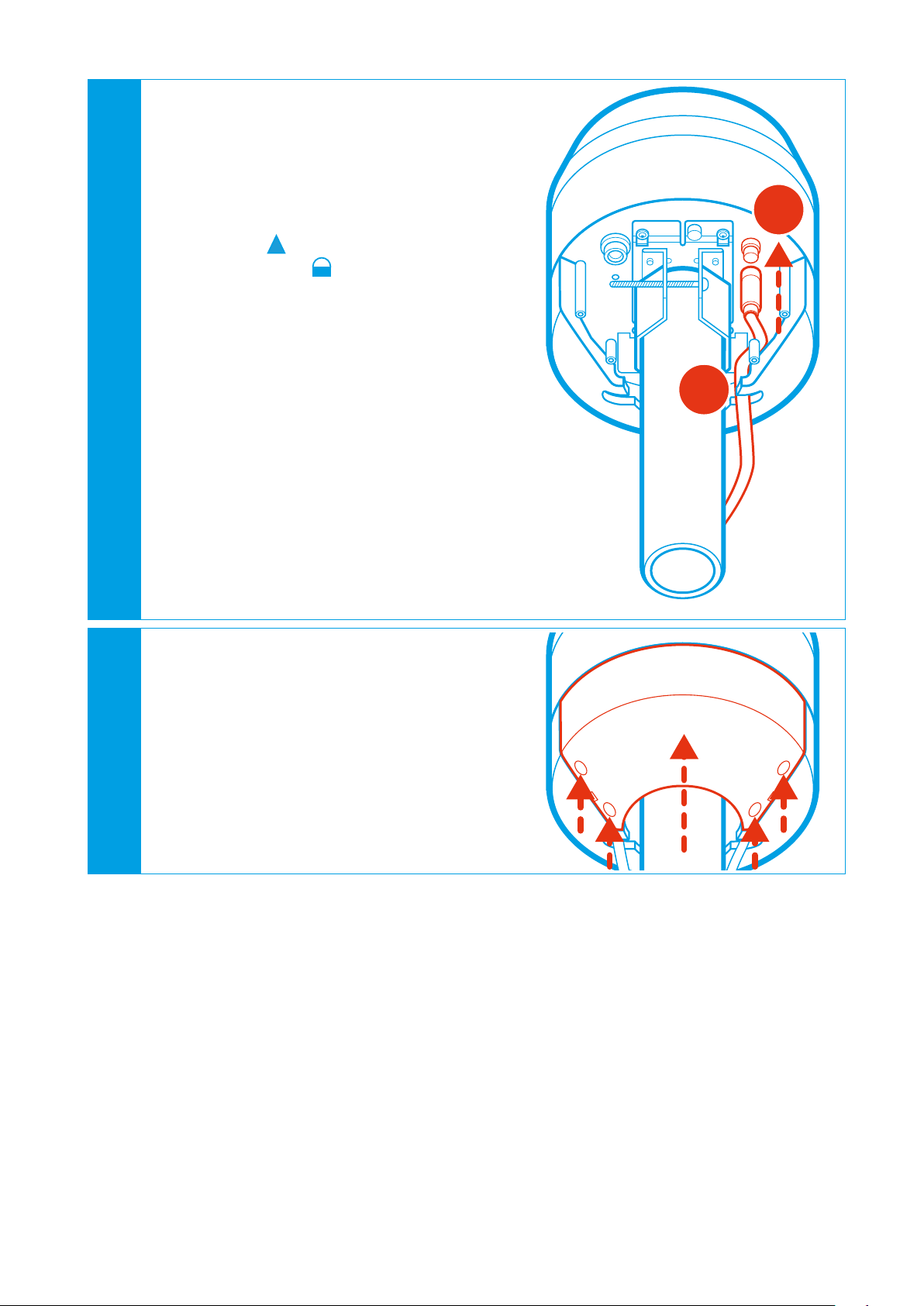
11 To connect the RF-160 to your local network,
connect the patch cable with the outdoor
housing to the network socket:
•Remove the protective cap from the plug.
•Plug the Ethernet cable with the outdoor
housing into the plug (1). Make sure that
the plug orientation fits the socket.
•Rotate the housing until it is locked (2).
•Lay the cable in the cable guide (3).
If you want to operate the RF-160 via
PoE+, make sure that PoE+ (802.3at) is
enabled on the connected switch.
]If the patch cable is connected to the net-
work and PoE+ is activated, the RF-160
boots automatically and after approxi-
mately 1 second the blue button at the
RF-160 illuminates, indicating that the
hardware is ready.
\The patch cable is connected to the net-
work with activated PoE+ and the RF-160
does not boot automatically after appro-
ximately 1 second?
EPush the blue button and wait for it
to illuminate.
EMake sure that active PoE+ (802.3at)
is activated in your network.
EIf you do not want to operate the
RF-160 via PoE+, connect the AC cable
as described in the next step.
2
3
1
IM-Inst-RF160en v0.4
Dedrone
13
Integrate the RF-160 in your DroneTracker
7 Integrate the RF-160 in your DroneTracker
The integration procedure of the RF-160 in your DroneTracker depends on the system type:
•On premises installations using your local DroneTracker Server (see chapter 7.1 Integrate the
RF-160 in your on prem DroneTracker Server, page 13).
•Dedrone Cloud installations do not require any additional infrastructur and are connected to
the Dedrone Cloud (see chapter 7.2 Integrate the RF-160 via Dedrone Cloud, page 15).
7.1 Integrate the RF-160 in your on prem DroneTracker Server
To connect to the RF-160 DHCP-Services are required that automatically assign an IP address to
the RF-160. If the RF-160 and the DroneTracker Server are in the same Layer2 network they can be
connected directly. If the RF-160 and the DroneTracker Server are in different networks refer to the
Dedrone Planning Manual or consult your network administrator.
12 To operate the RF-160 via the supplied AC
cable, connect the AC cable to the AC socket:
•Remove the protective cap from the AC
plug.
•Plug the AC cable into the plug (1).
]The plug clicks into place and the
arrow on the plug points to the
lock symbol on the socket.
•Lay the cable in the cable guide (2).
•Plug the AC plug into the socket.
]If the AC cable carry current, the RF-160
boots automatically and after approxi-
mately 1 second the blue button at the
RF-160 illuminates, indicating that the
hardware is ready.
\The AC cable is connected to the socket
and the RF-160 does not boot automati-
cally after approximately 1 second?
EPush the blue button and wait for it
to illuminate.
EMake sure that the power connection
carry current.
1
2
13 Close the RF-160 cover:
•Put the cover on the RF-160.
]The cover locks in place.
•Screw down all cover screws.

Integrate the RF-160 in your DroneTracker Dedrone
14 v0.4 IM-Inst-RF160en
1 Start your web-browser and enter the address of your DroneTracker Server.
For an optimal use, Dedrone recommends Chrome or Firefox.
2 Log in the DroneTracker UI as an administrator or configurator. The default login
credentials are:
User: admin Password: dedrone
]The DroneTracker user interface appears.
3 Choose OPTIONS > Site Configuration.
4 Choose [Add] > Dedrone RF Sensor.
]The window Discovered Sensors appears.
5 Select the desired RF-160 and choose [OK].
]The RF-160 appears in the Site Explorer.
6 To sort the RF-160 in the Site Explorer, drag and drop the element to the desired position.
7 Choose [Save changes].
]The window Site Configuration disappears.
8 Choose OPTIONS > Map Editor..
9 •Choose [Add] > Sensor.
•Choose the desired RF-160 in the window Select sensor.
•Choose [OK].
]The RF symbol appears on the map.
10 Move the RF symbol per drag and drop on the installation position on the map.
If the sensor was installed and aligned with a GPS device enter the noted values in the
fields Longitude and Longitude.
11 To lock the settings activate the option Lock settings.
12 Choose [Save changes].
]The window Map Editor disappears.
Requirements:
`RF-160 is installed
`The power supply is working and the button at the RF-160 illuminates blue
`RF-160 is connected to the network
`The IP address of the DroneTracker Server is known
Procedure:
IM-Inst-RF160en v0.4
Dedrone
15
Integrate the RF-160 in your DroneTracker
7.2 Integrate the RF-160 via Dedrone Cloud
Requirements:
`RF-160 is installed
`The power supply is working and the LED at the RF-160 illuminates blue
`RF-160 is connected to the Dedrone Cloud
`The address of your Dedrone Cloud access is known (provided by Dedrone)
`The registration key of the sensor is available (provided by Dedrone)
Procedure:
1 Start your web-browser and enter the address of your Dedrone Cloud.
For an optimal use, Dedrone recommends Chrome or Firefox.
2 Log in the DroneTracker UI as an administrator or configurator.
3 Choose OPTIONS > Site Configuration.
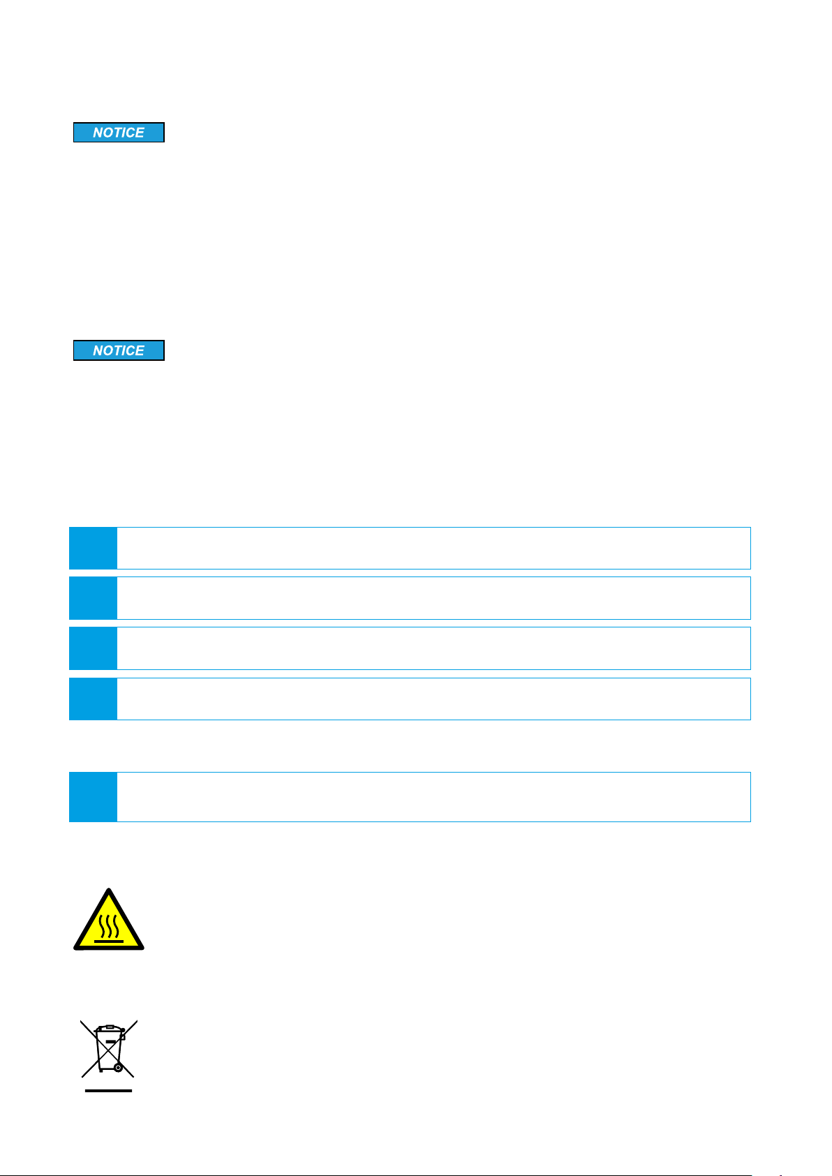
4 Choose [Add] > Register device.
]The window Register device appears.
5 Enter the registration key of your sensor and choose [OK].
]The RF-160 appears in the Site Explorer.
6 To sort the RF-160 in the Site Explorer, drag and drop the element to the desired position.
7 Choose [Save changes].
]The window Site Configuration disappears.
8 Choose OPTIONS > Map Editor and choose the RF-160.
9 •Choose [Add] > Sensor.
•Choose the desired RF-160 in the window Select sensor.
•Choose [OK].
]The RF symbol appears on the map.
10 Move the RF symbol per drag and drop on the installation position on the map.
If the sensor was installed and aligned with a GPS device enter the noted values in the
fields Longitude and Longitude.
11 To lock the settings, choose the option Lock settings.
12 Choose [Save changes].
]The window Map Editor disappears.
Cleaning Dedrone
16 v0.4 IM-Inst-RF160en
9 Decommissioning
9.1 Shut down the RF-160
RF-160 breaks
By disconnecting the cable of the power supply without shut down the RF-160, the RF-160 could
break.
•Always shut down the RF-160 before disconnecting the cable.
You have the possibility to shut down the RF-160 via the DroneTracker user interface or directly on
the sensor.
Shut down via DroneTracker user interface:
1 Log in to the DroneTracker UI.
2 Choose OPTIONS > Site Configuration.
3 Right-click on the desired RF-160.
4 Choose System > Shutdown hardware.
Briefly press the activation button at the RF-160 in the grip recess.
]The RF-160 shuts down and the blue light goes out.
Shut down directly at the RF-160:
9.2 Dismantling
9.3 Disposal
Dispose the RF-160 at the end of its service life in accordance with the disposal re-
gulations for electronic waste which apply at the installation location at that time.
Alternatively, send it back to Dedrone GmbH with shipping paid by sender, and labe-
led "ZUR ENTSORGUNG" ("FOR DISPOSAL").
8 Cleaning
Wrong cleaner damages the housing
The wrong cleaner can damage the housing or antenna of the RF-160. Never use glass cleaner or
other solvent cleaner to clean the RF-160.
•Use solvent-free cleaner to clean the RF-160.
Hot surface due to permanent sunlight
The surface of the RF-160 may become hot from permanent strong sunlight.
•Wear safety gloves when dismantling the device.

IM-Inst-RF160en v0.4
Dedrone
17
Technical Data
Range (line of sight) 0.65 mi (1.0 km)
In ideal conditions up to 1.3 mi (2 km)
Device Type Sensor
Radio Frequency Omnidirectional passive detection and classification
L x W x H 1 ft x 1 ft x 1.3ft (300 mm x 300 mm x 395 mm)
Weight 12.2 lb (5.5 kg)
Ingress Protection Rating IP65 *
Operating Temperature -4 °F to +131 °F (-20 °C to +55 °C)
Power Supply AC 100-240V 50/60 Hz max. 1 A or
PoE+ IEEE 802.3at (25 W)
Connectivity Via LAN to existing IT infrastructure or via the integrated
mobile connection in the Dedrone Cloud
Configuration, Operation, and
Alarms
Via DroneTracker software (software version >= 4.1 and valid
license)
Software Updates Firmware and DroneDNA updates via cloud-based
connection
10 Technical Data
* No ingress of dust; complete protection against contact (dust tight). A vacuum must be applied. Water projected by a
nozzle (6.3 mm) against enclosure from any direction shall have no harmful effects.
AIRSPACE
SECURITY
SOLUTION
Dedrone GmbH
Miramstraße 87
34123 Kassel
Germany
+ -
+
www.dedrone.com
Dedrone Holding, Inc.
220 Sansome Street
San Francisco, CA 94104
USA
Table of contents
Other Dedrone Accessories manuals


