DeeJay's Event Rentals INFLATABLE SCREEN User manual

! ! ! !
1!
!
!
!
!
!
INFLATABLE SCREEN
Instructions as of 3/22/17
!
!!!
SYSTEM COMPONENTS:
(1) Inflatable Movie Screen with storage bag
(8) Tie down straps (attached to screen)
(1) Air blower
(4) Steel twist-in stakes
(1) Tarp
!
!
2!
! ! !
!
!
!
!
!
!
!
!
!
!
6
(12’ screen pictured, not all screens are same proportions. For illustration purposes only )
INFLATABLE SCREEN SETUP
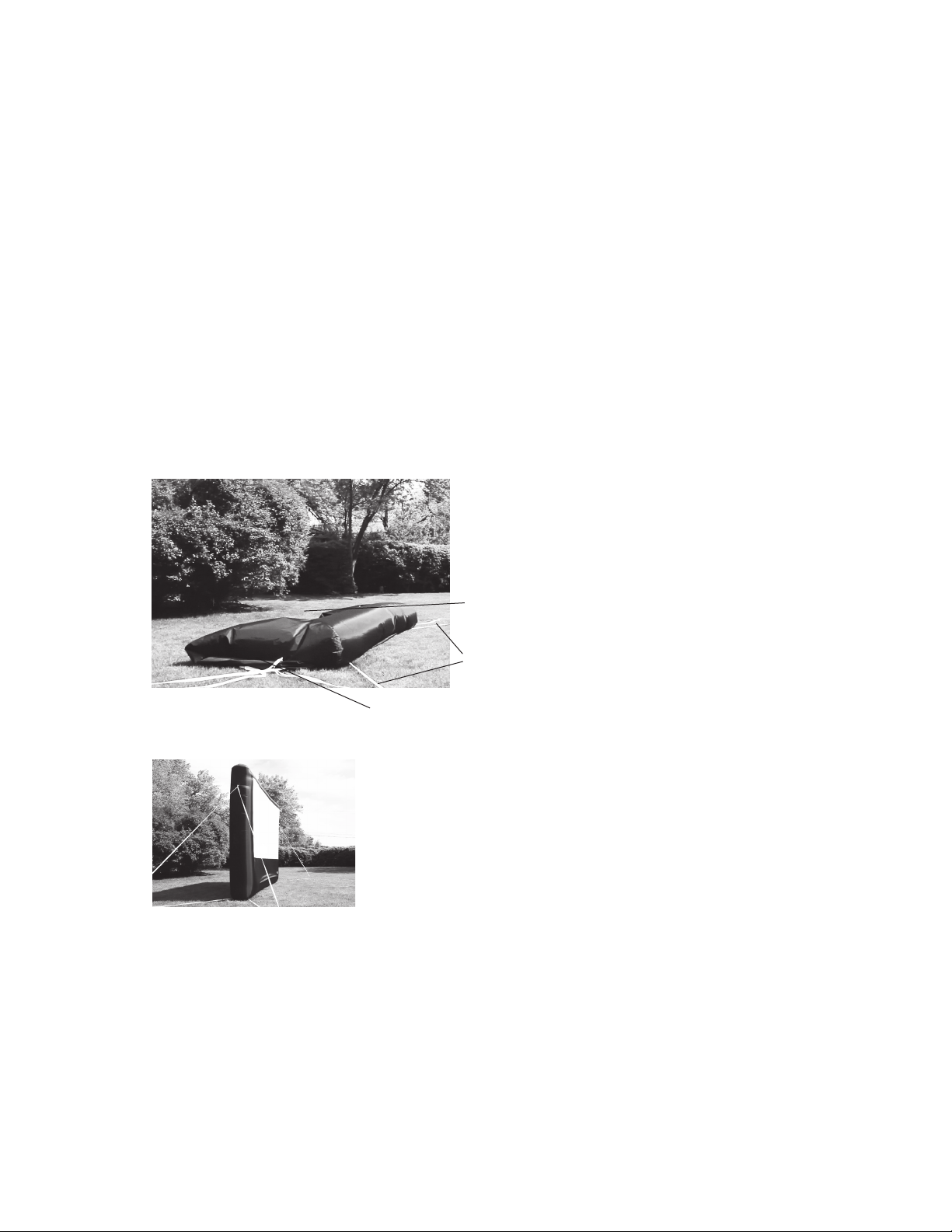
STEP 1: UNROLL SCREEN AND UNCOIL TETHERS
Unroll screen on grass or tarp. Unfold the screen so it sits like a
clamshell with the white projection surface on the inside (so it
doesn’t touch the ground). Identify the top and bottom of the
screen. The bottom of the screen has the air intake for the air
blower. Be sure ground is smooth, level and free of glass, rocks or
other debris.
Uncoil white tethers from four corners of screen, top and bottom.
Screen should be at least 10’ away from structures and objects such
as fences, buildings, trees, overhead branches, power lines, electrical
wires, walls, etc. Choose a location where no direct light will hit the
screen.
ATTENTION: Do not drag screen across concrete, pavement or
other rough surfaces.
Properly unfolded screen
Uncoiled white tethers
Rear side of screen
Front side of screen with white
projection surface inside of
clamshell like form
Preview of what screen will
look like when properly inflated.
Notice how there are two tethers
attached to each corner of the
screen, front and back. Do not
inflate yet.

! ! ! !
3!
!
!
!
!
!
!
!
!
!
!
!
!
!
7
(12’ screen pictured, not all screens are same proportions. For illustration purposes only )
STEP 2: SECURE STAKES AND TETHERS
Place stakes in ground roughly 10 feet from the corners of screen at
135 degree angles.
For 9’, 12’, and 16’ screens, clip the tethers from the corners of the
screen to the stakes. For the 20’ screen, tie ends of tethers to stake,
preferrably using a clove hitch knot.
There are eight tethers total, four attached to the top of the screen,
four to the bottom. Make sure bottom tethers are taut when
connected to stakes, but leave about 3 feet of slack in the top
tethers. Tether length can be adjusted using the black sliders on each
tether.
ATTENTION: Be aware of any underground pipes or utilities before
driving stakes into the ground.
Place stakes in ground Attach tethers to stakes with clips
INFLATABLE SCREEN SETUP
Properly attached
stakes and tethers
Front tethers
Rear tethers

!
4!
!
!
!
!
!
!
!
!
!
!
!
!
!
8
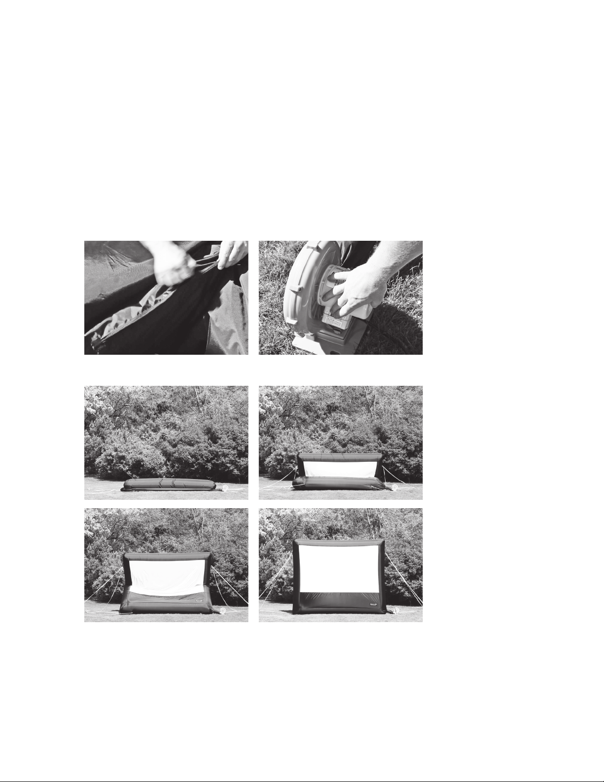
STEP 3: ATTACH AIR BLOWER TO SCREEN
Attach the air blower to the intake sleeve on the side of the inatable
frame using the cinch cord. Plug in the air blower using an extension
cord (not provided with Home systems).
Be sure the cinch cord is secured tightly around the coupling of the
air blower. Place the air blower in an area where it will not suck in dirt
or leaves. Do not use near water. Do not block vents on blower.
Intake vent (left), and air blower (right) Pull intake vent over blower pipe
INFLATABLE SCREEN SETUP
Tighten cinch cord around blower pipe Properly attached intake vent
(Air blower model will vary with each screen size, for illustration purposes only)
! ! ! !
5!
!
!
!
!
!
!
!
!
!
!
!
!
!
!
9
STEP 4: INFLATE SCREEN
Close air vent(s) by zipping closed. Turn on the air blower’s power
switch. The Open Air Screen should inate in less than a minute.
The air blower should remain on to continuously maintain air pres-
sure during use. Airow through seams is normal. Do not try to seal
seams.
Zip air vent closed Turn on the air blower’s power switch
HOME INFLATABLE SCREEN SETUP
e Open Air Screen should inflate in less than a minute.
(Air blower model will vary with each screen size, for illustration purposes only. 12’ screen pictured. )

!
6!
!
!
!
!
OVERHEAD VIEW OF SCREEN PLACEMENT – Front or Rear Projection
!
!
!
!
!
!
!
!
!
!
!
!
!
!
!
!
!
!
!
!
!
!
!
!
!
!
!
!
!
!
!
!
!
!
!
!
!
!
!
!
!
12 CINEBOX™ CONSOLE SETUP
STEP 1: CINEBOX™ AND PROJECTOR PLACEMENT
Center the video projector and CineBox™ Console in front of the
Open Air Home Screen at approximately the distance listed on the
chart below for your specic system size. Place on small table.
The projector’s zoom function will allow for image size adjustment
after the projector has been placed.
DISTANCE TO PLACE CINBOX™ CONSOLE FROM
CENTER OF SCREEN BY SYSTEM SIZE:
9’ Home System
12’ Home System
16’ Home System
20’ Home System
14 feet
18 feet
24 feet
30 feet
Center console to
screen at the distance
specified above
CineBox™ Console
Stakes and
tethers
Speakers
Front of screen
Air blower
(illustration not to exact scale)
Video projector
Overhead View of
system and console
setup
Projector - Rear
12 CINEBOX™ CONSOLE SETUP
STEP 1: CINEBOX™ AND PROJECTOR PLACEMENT
Center the video projector and CineBox™ Console in front of the
Open Air Home Screen at approximately the distance listed on the
chart below for your specic system size. Place on small table.
The projector’s zoom function will allow for image size adjustment
after the projector has been placed.
DISTANCE TO PLACE CINBOX™ CONSOLE FROM
CENTER OF SCREEN BY SYSTEM SIZE:
9’ Home System
12’ Home System
16’ Home System
20’ Home System
14 feet
18 feet
24 feet
30 feet
Center console to
screen at the distance
specified above
CineBox™ Console
Stakes and
tethers
Speakers
Front of screen
Air blower
(illustration not to exact scale)
Video projector
Overhead View of
system and console
setup
Projector - Front
**For Rear Projection**
Roll up back black panel and secure
to screen with attached velcro loops.

! ! ! !
7!
! !
!
STEP 5: SETUP OTHER DEVICES
!
PROJECTOR;
Place PROJECTOR on small table.
Plug Power Cord in.
DVD PLAYER or LAPTOP;
Plug HDMI Cable into HDMI port of DVD PLAYER or LAPTOP. Plug other end into
PROJECTOR.
Plug Power Cord in.
SPEAKERS;
Place SPEAKERS on stands on each side of the screen. **TURN all volume knobs all the
all the way down (counter clockwise).
Attach XLR Cable from output of one SPEAKER to input of the other SPEAKER.
Connect Primary SPEAKER to DVD PLAYER or LAPTOP via IPOD CABLE.
Plug Power Cord in.
Power on PROJECTOR
Power on DVD PLAYER or LAPTOP
Power on SPEAKERS, adjust volume for sound check by playing DVD or video on LAPTOP.
IMAGE ALIGNMENT
Turn on DVD and/or video on LAPTOP to make any image adjustments using the adjustable
feet on PROJECTOR, as well as ZOOM, FOCUS, and KEYSTONE features of projector.
!
!
17
WATCH YOUR MOVIE
You’re all ready to watch your movie, so sit back, relax, and enjoy!
For troubleshooting steps, see next page.
SYSTEM TAKEDOWN
Power down projector by pushing power button on top of projector
or by using remote. Make sure projector cools down completely
before unplugging or turning off power source. Failure to do so
could result in projector or bulb damage.
Turn down all audio and other knobs on mixers and speakers.
Power down all electronic components and neatly coil all cables.
Zip up CineBox™ console. Take down speaker stands and return to
speaker stand cases (for 16’ and 20’ systems).
Turn off air blower and guide the screen down so that it folds in half
(top to bottom, as shown on step one of screen setup). Unzip the
air vent and disconnect the intake sleeve from air blower. Unclip or
untie tethers from stakes. Remove stakes from ground and clean off
any debris or dirt.
Fold the screen from back to front a few times until it is in a long
strip about two feet wide. Roll tightly and place in protective travel
bag.
ATTENTION: Prevent the projection surface from touching the
ground. Do not pack the screen if it is wet. Hang the screen
indoors if necessary to dry before storage.

!
8!
!
STEP 6: SYSTEM TAKEDOWN
PROJECTOR
Power down the projector; press power button and follow instructions to allow projector bulb
to cool down BEFORE unplugging. Failure to do so could result in bulb damage and
replacement fees.
SPEAKERS
Turn all volume knobs down on speakers and turn to OFF position before unplugging cables.
SCREEN
Turn off air blower and guide screen down so that it unfolds in half (top to bottom, as shown in
screen setup).
Unzip air vent and disconnect the intake sleeve from air blower.
Unclip or untie tethers from stakes.
Remove stakes from ground and clean off debris / dirt with a rag.
Fold screen from back to front a few times until it is in a long strip about 2 feet wide. Roll
tightly and place in travel bag.
NOTE: PREVENT SCREEN SURFACE FROM TOUCHING THE GROUND. DO NOT PACK IF
SCREEN IS WET. HANG INDOORS IF NECESSARY, TO DRY SCREEN BEFORE STORAGE.
!
!
!
!
!
!
!
!
!
!
Table of contents
Popular Projector Accessories manuals by other brands


Grandview
Grandview Prestige PP R1 Series user manual

ShowTex
ShowTex HiSpeed Roll Up user manual

WAGNER
WAGNER WiGA35 Quick installation guide

Strong
Strong SM-PROJ-L-WH instruction manual

Navitar
Navitar 648MCL1028 installation instructions

Mounting Solutions
Mounting Solutions PAP Long Series Assembly guide


