DO GUIDE DOC. 7715A (2042373) 04.15
Specications subject to change without notice.
NOTE: Tie all source and device grounds to the ground terminal.
Ensure the unit is properly grounded by connecting the chassis
ground lug to an earth ground (building steel).
NOTE: To prevent overheating, do not operate this product in an
area that exceeds the environmental temperature range listed in
the table of specications on the Crestron website.
NOTE: For optimum performance, Crestron recommends using
DM-CBL-8G DigitalMedia™ cable.
DO Learn More
Check the website for additional information
and the latest rmware updates.
Crestron Electronics
15 Volvo Drive, Rockleigh, NJ 07647
888.CRESTRON | www.crestron.com
As of the date of manufacture, the DMPS3-300-C-AEC, DMPS3-300-C, and DMPS3-200-C
have been tested and found to comply with specications for CE marking.
This product is Listed to applicable UL Standards and requirements by Underwriters
Laboratories Inc.
Federal Communications Commission (FCC) Compliance Statement
This device complies with part 15 of the FCC Rules. Operation is subject to the following conditions:
(1) This device may not cause harmful interference and (2) this device must accept any interference
received, including interference that may cause undesired operation.
Caution: Changes or modications not expressly approved by the manufacturer responsible for
compliance could void the user’s authority to operate the equipment.
Note: This equipment has been tested and found to comply with the limits for a Class B digital device,
pursuant to part 15 of the FCC Rules. These limits are designed to provide reasonable protection
against harmful interference in a residential installation. This equipment generates, uses and can
radiate radio frequency energy and, if not installed and used in accordance with the instructions, may
cause harmful interference to radio communications. However, there is no guarantee that interference
will not occur in a particular installation.
If this equipment does cause harmful interference to radio or television reception, which can
be determined by turning the equipment off and on, the user is encouraged to try to correct the
interference by one or more of the following measures:
• Reorient or relocate the receiving antenna
• Increase the separation between the equipment and receiver
• Connect the equipment into an outlet on a circuit different from that to which the receiver is
connected
• Consult the dealer or an experienced radio/TV technician for help
FCC Compliance Information
1. This equipment complies with Part 68 of Federal Communications Commission (FCC) rules and
requirements adopted by America’s Carriers Telecommunications Association (ACTA). Each
registered interface has a label that contains, among other information, a product identier in the
format US: CTUMM00BDMPS3300AEC. If requested, provide this information to the telephone
company.
2. If this equipment causes harm to the telephone network, the telephone company may temporarily
discontinue service. If possible, advance notication is given; otherwise, notication is given as
soon as possible. The telephone company will advise the customer of the right to le a complaint
with the FCC.
3. The telephone company may make changes in its facilities, equipment, operations, or procedures
that could affect the proper operation of this equipment. Advance notication and the opportunity
to maintain uninterrupted service are given.
4. If experiencing difculty with this equipment, please contact manufacturer for repair and warranty
information. The telephone company may require this equipment to be disconnected from the
network until the problem is corrected, or it is certain the equipment is not malfunctioning.
5. This unit contains no user-serviceable parts.
6. This equipment is designed to connect to the telephone network or premises wiring using an
FCC-compatible modular jack, which is compliant with Part 68 and requirements adopted by
ACTA.
7. The ringer equivalence number (REN) is useful in determining the quantity of devices you may
connect to your telephone line and still have all of those devices ring when your number is called.
In most areas, the sum of the RENs of all devices should not exceed ve. To be certain of the
number of devices you may connect to your line as determined by the REN, call your telephone
company to determine the maximum REN for your calling area.
8. This equipment may not be used on coin service provided by the telephone company. Connection
to party lines is subject to state tariffs. Contact your state public utility commission or corporation
commission for information.
Industry Canada (IC) Compliance Statement
CAN ICES-3(B)/NMB-3(B)
REN IC 0.1
This product meets the applicable Industry Canada technical specications.
The Ringer Equivalence Number (REN) is an indication of the maximum number of devices allowed to be
connected to a telephone interface. The termination of an interface may consist of any combination of
devices subject only to the requirement that the sum of the RENs of all the devices not exceed ve.
Le présent matériel est conforme aux specications techniques applicables d’Industrie Canada.
L’indice d’équivalence de la sonnerie (IES) sert à indiquer le nombre maximal de terminaux qui peuvent
être raccordés à une interface téléphonique. La terminaison d’une interface peut consister en une
combinaison quelconque de dispositifs, à la seule condition que la somme d’indices d’équivalence de
la sonnerie de tous les dispositifs n’excède pas cinq.
ACTA Compliance Information
REN US 0.0B
The Ringer Equivalence Number (REN) indicates the maximum number of devices allowed to be
connected to a telephone interface. The termination of an interface may consist of any combination of
devices subject only to the requirement that the sum of the RENs of all the devices not exceed ve.
Rack Mounting Safety Precautions
• Elevated Operating Ambient Temperature: If installed in a closed or multi-unit rack assembly,
the operating ambient temperature of the rack environment may be greater than room
ambient temperature. Therefore, consideration should be given to installing the equipment in
an environment compatible with the maximum ambient temperature (Tma) specied by the
manufacturer.
• Reduced Airow: Installation of the equipment in a rack should be such that the amount of airow
required for safe operation of the equipment is not compromised.
• Mechanical Loading: Mounting of the equipment in the rack should be such that a hazardous
condition is not achieved due to uneven mechanical loading.
• Circuit Overloading: Consideration should be given to the connection of the equipment to the
supply circuit and the effect that overloading of the circuits might have on overcurrent protection
and supply wiring. Appropriate consideration of equipment nameplate ratings should be used
when addressing this concern.
• Reliable Earthing: Reliable earthing of rack-mounted equipment should be maintained. Particular
attention should be given to supply connections other than direct connections to the branch
circuit (e.g., use of power strips).
The specic patents that cover Crestron products are listed at www.patents.crestron.com.
The product warranty can be found at www.crestron.com/warranty.
Crestron, the Crestron logo, 3-Series, Cresnet, DigitalMedia, DM, and DM 8G+ are either trademarks or registered trademarks
of Crestron Electronics, Inc. in the United States and/or other countries. HDMI and the HDMI logo are either trademarks or
registered trademarks of HDMI Licensing LLC in the United States and/or other countries. UL and the UL logo are either
trademarks or registered trademarks of Underwriters Laboratories, Inc. in the United States and/or other countries. Other
trademarks, registered trademarks, and trade names may be used in this document to refer to either the entities claiming the
marks and names or their products. Crestron disclaims any proprietary interest in the marks and names of others. Crestron is
not responsible for errors in typography or photography.
This document was written by the Technical Publications department at Crestron.
©2015 Crestron Electronics, Inc.
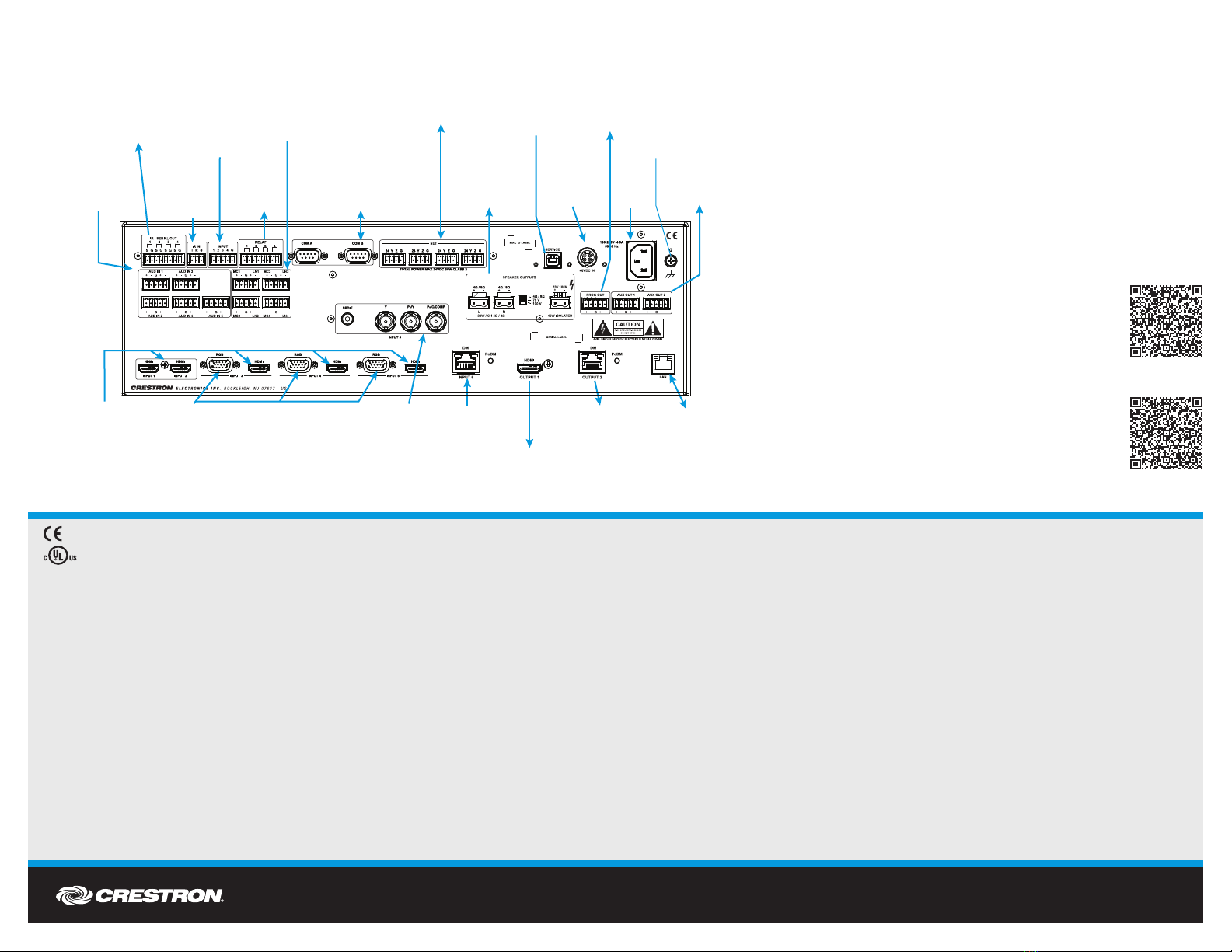
RELAY:
Output to
Controllable
Devices
IR-IN:
From
CNXRMIRD
IR Receiver
INPUT:
From Device
Outputs Contact or
Relay Closures (24
Volts Max) Serial
Controlled Devices
IR-SERIAL OUT:
To IRP2 IR Emitter Probe
or One-Way Serial
Controlled Devices
NET:
To/From Any
Cresnet Device
POWER:
From Line
Voltage
PROG OUT:
Program Audio Output
To Amplifier or
Amplified Speakers
MC/LN 1 - 4:
From Balanced
Microphone/Line
Audio Inputs
From Microphone or
Line-Level Sources
RGB 3 - 5:
Input From Analog
RGB/Video Sources
HDMI INPUT 1 - 5:
From Digital
Video/Audio Sources
SPEAKER OUTPUTS:
To 4W/8W Stereo
Speakers, or 70/100
Volt
Mono Speakers
AUD IN 1 - 5:
From Video and
RGB Sources or
Codec Output
DM INPUT 6:
From 8G+
DM Transmitter
DM OUTPUT 2:
To DM 8G+ Input of DM
Receiver/Room Controller
RGB/Video Sources
HDMI OUTPUT 1:
To Digital Video/
Audio Devices
INPUT 5:
From SPDIF,
Component,
S-Video, or
Composite Sources
RGB/Video Sources
LAN:
10/100/1000 BASE-T
Ethernet to LAN
GROUND
USB-HID:
For Future
Use
PoDM:
48 VDC Input
From Power
Pack
PoDM
AUX OUT 1, 2:
To VTC or Audio Mixer
or Codec Output
COM A and COM B:
Bi-Directional RS-232 with
Hardware and Software
Handshaking and
Modem Control
Connections to the DMPS3-200-C
DMPS3-200-C
DMPS3-300-C
DMPS3-300-AEC-C


