Deep Trekker DTG2 User manual
Deep Trekker DTG2 User Manual
Version 2.0 2016
06-9915-01-01 to 06-9915-01-100
06-9916-01-01 to 06-9915-01-200

DEEP TREKKER DTG2 USER MANUAL
DEEP TREKKER INC.
2
Warning
Never operate your DTG2 in the presence of unaware swimmers or divers.
Always use a Personal Flotation Device (PFD) and obey any laws pertaining to the operation of your
launch vehicle.
NOTE: Because of the sharp running hardware included with this product, we do not recommend a
rubber blow up raft.
Extreme caution should be taken if piloting the DTG2 ROV in swimming pools, as the sharp edges
could damage the pool liner.
The DTG2 running hardware is very sharp. Be very careful when working on and around the parts.
While the motor is running pay close attention to the propeller. Do not come in contact, or put
fingers near the propeller at any time the system is turned on or serious injury will result.
The speed and mass of this DTG2 ROV can inflict property damage and severe personal injury if a
collision occurs. Never run this ROV in the presence of unaware swimmers or boaters or where the
possibility of collision with people or property exists.
The density of each body of water is different, before operation in a new body of water, adjusting
the weight of the ROV is necessary to avoid damage to the ROV or property around it. Each DTG2
ROV is equipped with ballast weights to place under the handles or on the bottom of the ROV.
Deep Trekker products are to be used by people 16 years of age and over.
Always read the owner’s manual before operation.

DEEP TREKKER DTG2 USER MANUAL
DEEP TREKKER INC.
3
Contents
Warning........................................................................................................................................................................................................ 2
Safety Precautions ....................................................................................................................................................................................... 4
Manual Specification and Description Changes ........................................................................................................................................... 5
Delivery and Inspection ................................................................................................................................................................................ 6
System Overview .......................................................................................................................................................................................... 7
Calibrating the Buoyancy ........................................................................................................................................................................... 11
Launching your First Dive ........................................................................................................................................................................... 12
Operation ................................................................................................................................................................................................... 13
On / Off ........................................................................................................................................................................................... 13
Driving Controls .............................................................................................................................................................................. 13
Thruster Trim .................................................................................................................................................................................. 14
Pitch Trim ........................................................................................................................................................................................ 14
Gain /Scroll Buttons ........................................................................................................................................................................ 14
Primary Flood Lights........................................................................................................................................................................ 15
Auxiliary Flood Lights (Optional Equipment) ................................................................................................................................... 15
Camera Up/Down Buttons .............................................................................................................................................................. 15
Forward Camera ............................................................................................................................................................................. 15
Camera Lock .................................................................................................................................................................................... 15
Pitch Lock ........................................................................................................................................................................................ 16
Reset ............................................................................................................................................................................................... 16
Grabber Open/Close Buttons (Optional Equipment) ...................................................................................................................... 16
Grabber Rotate Buttons (Optional Equipment) .............................................................................................................................. 16
LED Indicators: ................................................................................................................................................................................ 17
Menu Button ................................................................................................................................................................................... 17
Tether: ............................................................................................................................................................................................ 18
Entanglement: ................................................................................................................................................................................. 18
Shutdown ................................................................................................................................................................................................... 19
Charging ..................................................................................................................................................................................................... 19
Storage ....................................................................................................................................................................................................... 21
Transporting ............................................................................................................................................................................................... 22
Optional Equipment - Sensor System ......................................................................................................................................................... 23
Auto-Depth ..................................................................................................................................................................................... 24
Auto-Heading .................................................................................................................................................................................. 24
Turns Counter ................................................................................................................................................................................. 25
On Screen Display On/Off ............................................................................................................................................................... 25
Calibrating the Compass ................................................................................................................................................................. 25
Optional Equipment – Two Function Grabber ........................................................................................................................................... 26
Optional Equipment – Auxiliary Lighting .................................................................................................................................................... 28
Optional Equipment – Laser Scaler ............................................................................................................................................................ 28
Optional Equipment – Crawler Wheels ...................................................................................................................................................... 28
Optional Equipment – Auxiliary Camera(s) ................................................................................................................................................ 29
Optional Equipment – Digital Video Recorder (DVR) ................................................................................................................................. 30
Optional Equipment – Video Glasses ......................................................................................................................................................... 35
Mounting Provisions for Auxiliary Equipment ............................................................................................................................................ 36
Maintenance .............................................................................................................................................................................................. 37
Window Repair........................................................................................................................................................................................... 38
Removing the Tether .................................................................................................................................................................................. 39
Re-Installing the Tether .............................................................................................................................................................................. 40
Trouble Shooting ........................................................................................................................................................................................ 43
Using the Diagnostics Cable ....................................................................................................................................................................... 45
Diagnostics Screens .................................................................................................................................................................................... 46
Parts and Service ........................................................................................................................................................................................ 48
Warranty .................................................................................................................................................................................................... 50

DEEP TREKKER DTG2 USER MANUAL
DEEP TREKKER INC.
4
Safety Precautions
Never attempt to swim after a stalled DTG2. Do not get in the water for any reason to retrieve your
DTG2. Return the DTG2 by gently pulling it back to the boat by the tether. In cases where the
tether is snagged or severed, contact a certified diver to perform the retrieval for you.
Deep Trekker products are to be used by those aged 16 and over.
Do not touch the propeller when the motor is spinning. Pay equally close attention to items such as
loose clothing, shirtsleeves, ties, scarves, long hair or anything that may become entangled in the
spinning propeller. If your fingers, hands, etc. come in contact with the spinning propeller, you may
be severely injured.
Keep your launching and piloting area tidy and your tether neatly rolled to avoid tripping while
operating the DTG2.
The speed and mass of this DTG2 ROV can inflict property damage and severe personal injury if a
collision occurs. Never run this ROV in the presence of unaware swimmers or boaters or where the
possibility of collision with people or property exists.
Be aware of dangers around you, including weather, and obey all applicable laws while using
standard water safety procedures.
The density of each body of water is different, before operation in a new body of water, adjusting
the weight of the ROV is necessary to avoid damage to the ROV or property around it. Each DTG2
ROV is equipped with ballast weights to place under the handles or on the bottom of the ROV.
The DTG2 ROV is equipped with lithium ion batteries, completely enclosed in both the ROV and
controller. Under no circumstances try to open or disassemble the batteries, or expose the batteries
to extreme heat or mechanical shock such as dropping it on a hard surface. If you have not used the
battery pack for a considerable amount of time, the remaining battery life may shorten. The battery
pack will gradually discharge over time even while not in use. We recommend fully charging the
batteries every 6 months to ensure they do not fully self-discharge over time.

DEEP TREKKER DTG2 USER MANUAL
DEEP TREKKER INC.
5
Manual Specification and Description Changes
All pictures, descriptions, and specifications found in this instruction manual are subject to change
without notice. Deep Trekker Inc. maintains no responsibility for inadvertent errors in this manual.
DEEP TREKKER DTG2 USER MANUAL
DEEP TREKKER INC.
6
Delivery and Inspection
Thank you for purchasing the DTG2 inspection and exploration system; the world’s only premium grade,
portable, affordable and easy to use underwater ROV. We want the time you spend with your new
remotely operated vehicle (ROV) to be entertaining and successful so please read the entire manual
before using this product for the first time.
The DTG2 ROV is ready for use as delivered from the factory. The unit has been fully tested and
inspected prior to shipping, including a pressure test equivalent to the maximum dive depth.
Leaving the batteries fully drained for long periods of time will cause permanent damage. We
recommend fully charging them every 6 months to ensure they do not fully self-discharge over time.
For more information regarding the charging, see the section in the manual entitled Charging.
Fully inspect your ROV to ensure it has not been damaged during shipping. If you suspect a problem
please contact Deep Trekker support or your authorized Deep Trekker Dealer for assistance.
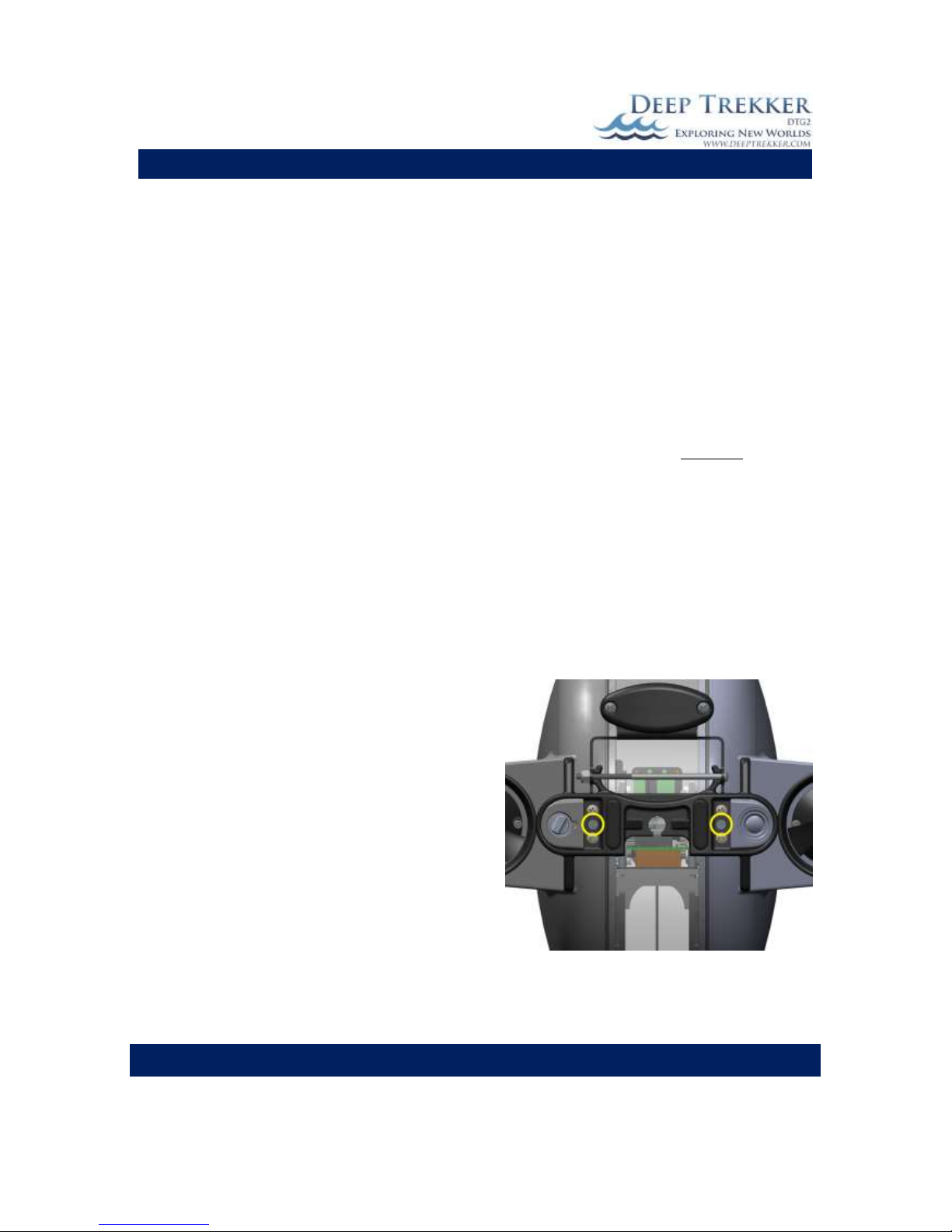
The DTG2 is shipped to you with the two shipping set screws in the locked position, the DTG2 will not
operate with these screws locked. This ensures that the rough motions associated with the delivery
service do not damage the internal frame and the servo motor that turns it.
To release the shipping set screws the following steps
must be taken.
1) Rotate ROV upside down with the handles facing
downward. This will ensure it does not rotate
until the screw is completely backed out. While in
this position, turn both set screws using a flathead
screwdriver counter-clockwise until the set screw
heads are firmly against the cover plate.
*DO NOT COMPLETELY REMOVE THE SHIPPING SET
SCREW UNDER ANY CIRCUMSTANCES. THIS OPENS
UP THE SEALED UNIT AND WILL LEAD TO IMMEDIATE
FAILURE IF SUBMERGED*
2) Slowly rotate ROV to its level position.
Fig 1
DEEP TREKKER DTG2 USER MANUAL
DEEP TREKKER INC.
7
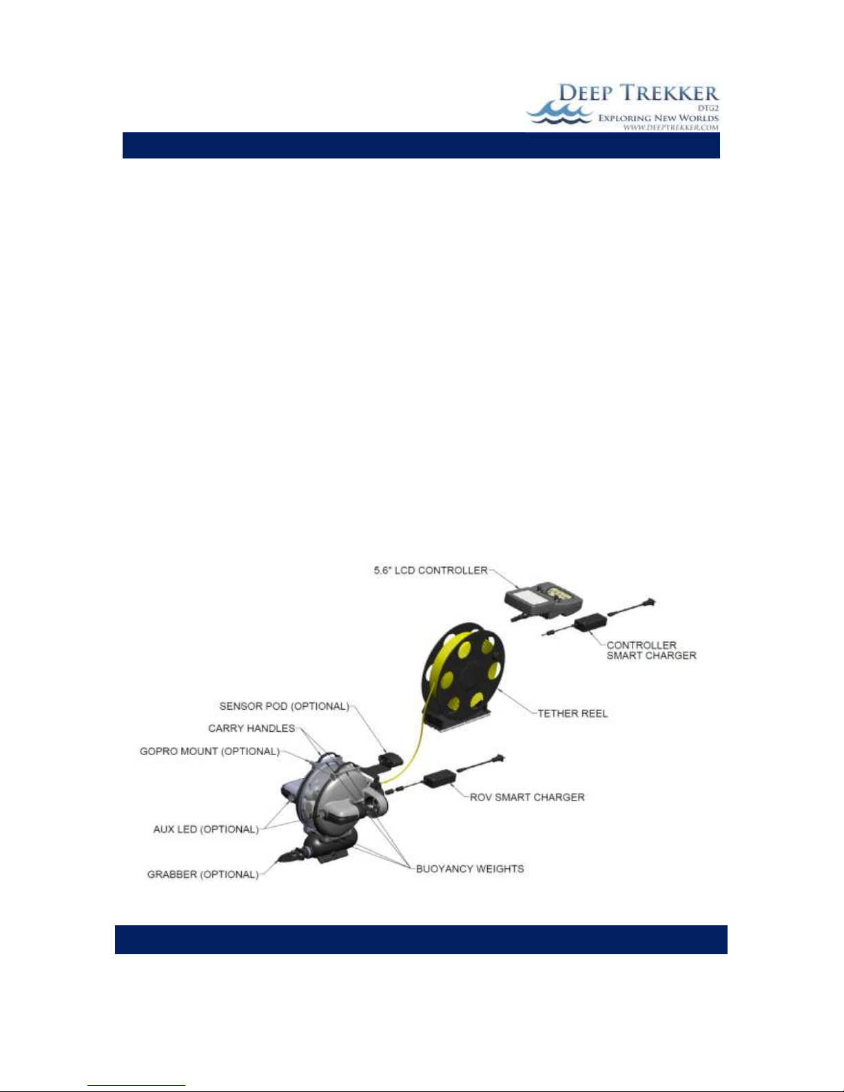
System Overview
The DTG2 ROV is designed to operate in fresh or salt water between the temperatures of -5C [23F] to
45C [113F]. This unique ROV incorporates internal/onboard batteries, so the system is completely
portable with no top side generator or box required. The tether is also much smaller and lighter than a
tether designed to carry power. The controller replicates a traditional game pad, reducing the learning
curve of successfully operating the DTG2 significantly.
The use of magnetic couplers means that there is no dynamic shaft seal on board the DTG2. This feature
dramatically increases reliability and requires no maintenance, greasing or replacing any seals on the
ROV.
The patented pitch control aims the outer shell (thrusters) to any angle +/- 90 degree from center for a
total of 180 degrees. This system that works entirely from within the hull, eliminates the requirement of
a third or fourth thruster and further increases reliability and ease of use.
The ROV and tether are 100% waterproof and should not take on water unless damaged. The standard
controller is splash resistant, but should not be submerged or power washed at any time. Other
optional viewing systems offered are not waterproof in any way and need to be used with care of in
outdoor environments. The ROV charger and controller charger are indoor products that should never
be operated near water or wet conditions.
Fig. 2A
DEEP TREKKER DTG2 USER MANUAL
DEEP TREKKER INC.
8
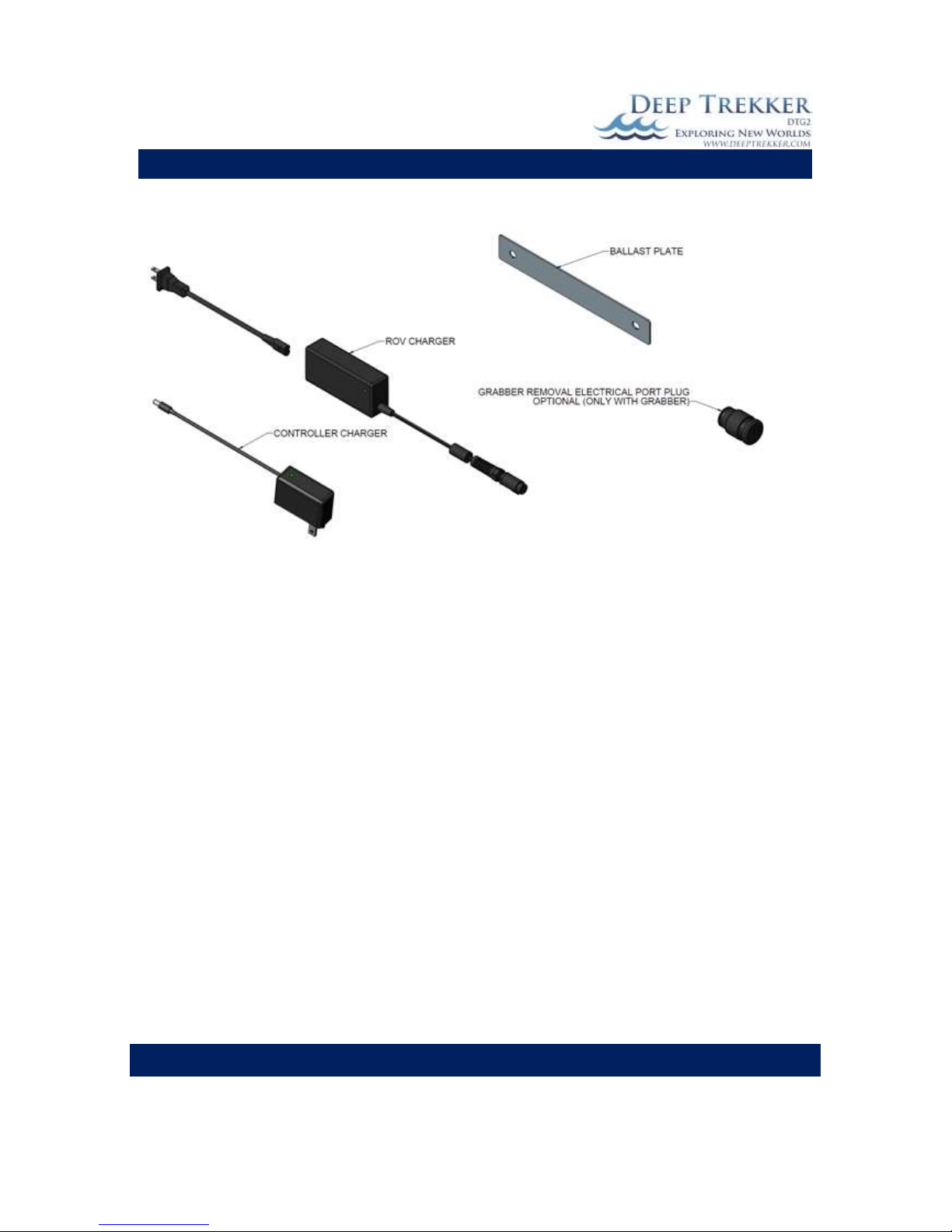
Fig. 2B

DEEP TREKKER DTG2 USER MANUAL
DEEP TREKKER INC.
9
Fig. 3A

DEEP TREKKER DTG2 USER MANUAL
DEEP TREKKER INC.
10
Fig. 3B

DEEP TREKKER DTG2 USER MANUAL
DEEP TREKKER INC.
11
Calibrating the Buoyancy
The DTG2 ROV is shipped from the factory calibrated for fresh water use. To adapt for salt water, simply
add the provided ballast plates, as shown in Fig. 4, evenly to the top mounting points or bottom
mounting points. These weights can be added or removed as desired to gain the preferred buoyancy. It
is most common to bias the buoyancy to a neutral or slightly positive setting.
Every body of water will have a different density, generally when changing to salt water, we recommend
adding 4 ballast plates to start. From there, small ballast plates can be added or removed to ensure
neutral buoyancy.
Fig. 4

DEEP TREKKER DTG2 USER MANUAL
DEEP TREKKER INC.
12
Launching your First Dive
Prior to operating the DTG2 system, ensure you have read the entire operator’s manual and fully
understand it. Once fully charged, remove the charger from the ROV and set it right side up on a secure
surface. This is important because as soon as the system is active the pitch system will rotate to this
level condition.
Turn the controller on with the ON/OFF button. The controller and ROV will enter the boot sequence
that should last no longer than 5 seconds. The video camera will come out of its upward park position
and point forward. The camera and light are now safe to use. The pitch system should not be activated
until the DTG2 is in the water, as it could cause the DTG2 to fall over unexpectantly.
Every dive should include a short inspection to ensure that everything is in order:
1) Check the thrusters for any debris that may be left from the prior dive.
2) Inspect the tether to ensure that it has not been worn or breached in any way.
3) Check for loose fasteners on the ROV.
4) Check the connection between the window and side bodies to ensure they are sealed.
5) Turn on the system and check functionality of the thrusters, lights and camera. Do not operate
the pitch system while out of water. The lights can run indefinitely while the ROV is out of water.
Once the inspection is complete prepare to launch using the following steps as a minimum:
1) Inform anyone nearby such as divers, swimmers, or boaters that you are deploying the DTG2
and its tether. Only deploy if you have their approval.
2) Ensure your launch and piloting areas are clean.
3) Ensure your tether is neat and ready to deploy.
For a first trial run, choose a safe shallow and clear body of water that does not include obstacles
capable of tangling the tether. There should be no wind or current present.
Lower the DTG2 into the water by the handles, or gently lower it in by the tether. Do not throw the
DTG2 into the water for risk of striking an object.
At this point it is advised to operate the ROV without relying on the camera and viewing system. Keep it
near the surface for easy visibility and familiarize yourself with the controls.
Once you are familiar with the controls of the ROV, you may begin to use solely the viewing screen to
maneuver the DTG2. We recommend keeping infrastructure or a stagnant object in view to keep your
orientation when learning.

DEEP TREKKER DTG2 USER MANUAL
DEEP TREKKER INC.
13
Operation
On / Off
The ON/OFF button as shown in Fig. 3A acts as an ON button when the ROV is
off, and an OFF button when the ROV is on. Pressing the on button starts a
boot sequence that will last about 4 seconds.
If the ROV is turned off while diving, simply turn it back on. It does not have
to be on dry land for a re-boot.
If the controls have not been activated on the controller for several minutes
the system will automatically shut down. This will shut down the controller
and ROV. If you are also using optional viewing systems such as the video
glasses or digital video recorder – these will not shut down automatically.
Driving Controls
As shown in Fig. 5, the motion of the DTG2 is accomplished with
only 2 joysticks. The left joystick completely controls the thruster
in an intuitive manner. Driving the DTG2 on a lateral plane.
Forward on the joystick is forward on the ROV. Back on the
joystick is reverse on the ROV. Right and left on the joystick are
turning the ROV right and left.
The patented pitch system rotates the entire outer body up and
down. This feature transforms the thrust motion from the
primary thrusters into vertical motion. Like an airplane, if you
point the jets up, it will climb, if you point them down it will
descend. The DTG2 is essentially the same thing in water, except
because it is the same weight as water (if you the operator
calibrated it correctly) it will remain at the same depth until the
thrusters move it up or down. Rotating the pitch system is
accomplished with the right joystick. Point the right joystick
forward to face the ROV downward. Pull the right joystick back
to point the ROV upward.
Drive Up
Drive Down
Fig. 5

DEEP TREKKER DTG2 USER MANUAL
DEEP TREKKER INC.
14
Thruster Trim
The right and left thrusters can be trimmed to ensure the ROV drives straight when the
joystick is full forward. Small variances in the ROV can pull it slowly to one side. To adjust
the thruster trim, place the ROV in an open body of water with no wave action or current.
Descend the ROV slightly below the water line so it is fully submerged but still visible by eye.
Throttle the thrusters full forward and observe the path it takes. Do not attempt to trim the
thrusters with the auto-heading or auto-depth engaged. (See Page 24 for more information
on auto-heading and auto-depth)
To calibrate the Thruster Trim: Press the MENU button, scroll down with the right joystick to
‘CALIBRATE’. Press the ‘2’ button to enter this menu. Use the right joystick to scroll down to
Trim Right or Trim Left. Press ‘2’ to trim the thruster 1% each time you select an option.
Pitch Trim
The pitch can be trimmed to hold any angle without using the pitch joystick. This allows an
operator to fine tune the “home” position of the tilt of the ROV to slightly up, perfectly
horizontal, or slightly down, depending on the operator’s preference. Do not attempt to trim
the pitch with the auto-heading or auto-depth engaged. (See Page 24 for more information
on auto-heading and auto-depth)
To calibrate the Pitch Trim: Press the MENU button, scroll down with the right joystick to
‘CALIBRATE’. Press the ‘2’ button to enter this menu. Use the right joystick to scroll down to
Trim Pitch Up or Dn. This will trim the ‘home’ position of the pitch 1 degree each time you
select an option using the ‘2’ button.
Gain /Scroll Buttons
The gain control can be adjusted on the hand controller to increase or decrease the speed of
the ROV. For example, in situations where there is no current and small precise movements
are necessary, reducing the gain may be beneficial. The Gain up/down buttons are located at
the front inner right hand side of the controller. The up button increases the ROV gain and
the down button decreases the ROV gain. When the gain buttons are used, your speed will
appear in the top center of the screen for 5 seconds. Once it disappears the gain has been
set. By default the ROV gain starts at 8 but can be increased up to 10 or decreased to 4. Gain
is the overall power sent to the thrusters, so an 8 is 80%, 5 is 50% and so on.
These arrows also function as scrolling buttons that activate immediately after various
other buttons are pressed. The user has 5 seconds to make adjustments to these settings
before the arrows return to gain adjust. There is always a scrolling number shown on
screen to allow the user proper feedback.
These gain control up/down button will also adjust these functions when they are first
activated.
1. Auxiliary Flood Light – use to scroll the intensity of the light. (0-100%)
2. Auto-Heading – Use to scroll to target heading (0-360 degrees)
3. Auto-Depth – Use to scroll to target depth (0-152 m [0-500 ft]

DEEP TREKKER DTG2 USER MANUAL
DEEP TREKKER INC.
15
Primary Flood Lights
The primary flood light button, shown in Fig. 3A, turns the primary flood lights on and off.
The primary floodlights are located inside the ROV mounted below the camera.
Auxiliary Flood Lights (Optional Equipment)
The auxiliary flood light button shown in Fig. 3A, turns the two auxiliary flood lights on and
off. The two auxiliary floodlights are located fixed to the shell at the front of the ROV.
Immediately after the auxiliary flood lights are turned on, an intensity level value defaulting
at 100% appears in the upper portion of the LCD screen. Use the gain arrows up and down
to adjust the level of light intensity. Once the arrow buttons are left unadjusted for more
then a few seconds the intensity value will disapear from the screen and the arrows will
return to the gain adjust.
Camera Up/Down Buttons
The camera up/down buttons are located at the front outer right hand side of the
controller. The up button rotates the camera up and the down button rotates the camera
down.
Forward Camera
The camera can quickly be aligned with the pitch angle, or in other words the forward
direction the ROV is headed, by pressing the Forward Camera button. This is helpful when
you want to look in the direction of motion without using the camera up/down arrows to
manually align it.
Camera Lock
The camera can be locked to the pitch angle by pressing the Camera Lock button. This
means that if the pitch angle changes by + 45 degrees, the camera angle will also change by
+45 degrees, ensuring that the camera is generally looking in the direction of travel at all
times. When the Camera Lock is first activated, the camera angle will be equal to the pitch
angle, however if you would like to offset the angle slightly, you can use the camera up and
down arrows. These are most useful when using the grabber and a fixed view of the
grabber claw is required.

DEEP TREKKER DTG2 USER MANUAL
DEEP TREKKER INC.
16
Pitch Lock
By default, when the unit is turned on, the pitch angle of the ROV follows the present
position of the pitch joystick (the right joystick). Since the joystick is “spring return to
center”, the body will also return to a 0 degree (horizontal) pitch when the operator’s
thumb is off the joystick. If the pitch lock button is pressed, the operation of the pitch
joystick scrolls the pitch angle up or down and when the joystick is released, the pitch
angle remains at the last selected angle. When the pitch lock mode is on, a target pitch
angle value is shown on the screen within (parentheses). This function is useful when
following a mooring line up or down on a constant angle. To release the pitch lock
back to center mode, simply press the pitch lock button again.
Reset
The Reset button is used to reset the thruster system or pitch system after a fault.
When the thrusters or pitch motor draw too much current, the ROV computer detects
this and shuts the system down in order to protect it. The most common cause of this
occurrence would be when the propeller is fowled. The system is re-activated after the
problem has been corrected by either pressing the reset button, or turning off/on the
entire ROV.
Grabber Open/Close Buttons (Optional Equipment)
The grabber open/close buttons are located at the front outer left hand side of the
controller. The up button opens the grabber claws and the down button closes the
grabber claws.
Grabber Rotate Buttons (Optional Equipment)
The grabber rotate buttons are located at the front inner left hand side of the
controller. The up button rotates the grabber claws Clockwise and the down button
rotates the grabber claws Counter Clockwise.

DEEP TREKKER DTG2 USER MANUAL
DEEP TREKKER INC.
17
LED Indicators
Check the controller’s LED indicators often.
When the ROV battery LED it flashing, the ROV will slow down considerably. Return it to the boat and
charge it when safely indoors.
When the low controller battery LED is flashing, you are very low on controller power and need to finish
the dive. If the controller battery is critically low, it will stop sending data to the ROV, rendering the
system unusable. Once the system is safely back indoors plug the controller charger into the controller
charge port as shown in Fig. 3B.
If the RH & LH thruster error LED light is on, return the ROV to the boat and turn the system off. Inspect
the propellers and magnetic coupler for binding objects. Removal of the guards and propeller may be
required. Once the debris is removed, turn on the system again and test the thrusters in and out of the
water. If the thruster error LED turns on again, contact Deep Trekker support or your authorized Deep
Trekker Dealer for assistance.
If the pitch stall LED turns on, simply press the reset thrusters/pitch button on the controller. The pitch
can be stalled by excessive pull on the tether or by trying to pitch the system out of the water. If the
pitch stall LED turns on again contact Deep Trekker support or your authorized Deep Trekker Dealer for
assistance.
The no communication & leak LED will turn on if: 1) the ROV is extremely low on batteries, 2) the tether
is unplugged or damaged or; 3) when the ROV is being charged. If a full battery charge does not fix the
problem, contact Deep Trekker support or your authorized Deep Trekker Dealer for assistance. See also
the trouble shooting guide portion of the manual. The second function of the no communication LED is
to warn of water intake into the ROV hull. The communication LED will flash quickly if water is sensed.
During this occurrence the ROV will become immobile and you must pull it out of the water as quickly as
possible and contact Deep Trekker support or your authorized Deep Trekker Dealer for assistance.
Menu Button
The Menu button allows access to the system settings, calibration and diagnostics tools.
Once the menus have been activated, scroll up or down with the right hand joystick and
make selections using the right hand joystick button.
DIAGNOSTICS
POWER shows system battery levels, current levels (see Diagnostics Section for detail)
COMMUNICATIONS shows system communication status (see Diagnostics Section for detail)
BUTTONS shows the buttons status on the controller (see Diagnostics Section for detail)
CONTROLLER shows the joysticks& misc. status on the controller (see Diagnostics Section for detail)
ROV shows the ROV status on the controller (see Diagnostics Section for detail)
EXIT

DEEP TREKKER DTG2 USER MANUAL
DEEP TREKKER INC.
18
CALIBRATE
TRIM PITCH UP Trim the home position of the pitch up 1 degree per press (see Pitch Trim for detail)
TRIM PITCH DN Trim the home position of the pitch down 1 degree per press (see Pitch Trim for detail))
TRIM RIGHT Trim the thrusters right - 1% per press (see Thruster Trim for detail)
TRIM LEFT Trim the thrusters left - 1% per press (see Thruster Trim for detail)
DEPTH 0M Set the 0m depth (on land) setting. Required for atmosphere and temperature changes
FACTORY D –ROV Return all calibration settings to factory default settings
EXIT
SETUP
UNITS: Select the units of measure (Imperial or metric)
LANGUAGE: Select the language
OSD: Turn on or off the On-Screen-Display (OSD)
EXIT
EXIT
Tether:
It is advised to have an assistant managing the tether as the ROV demands more let into the water, or
pulled back out of the water. Leaving too much tether in the water will cause excess drag on the DTG2,
and not having enough will restrict the ROV manoeuvrability. The tether needs to be closely observed
while in use as it poses a threat to swimmers, divers, and boaters.
Do not bend the tether in a radius of 75mm (3”) or less. Do not kink the tether. Never drag the tether
over a rough or sharp surface. This will quickly wear the outer protective jacket and eventually flood the
cable.
Do not step on or drive over the tether. Crushing the tether in any way may damage it in a fashion that
is non-repairable. If your tether does become damaged please contact Deep Trekker support or your
authorized Deep Trekker Dealer for assistance. Under no circumstances is a damaged tether from the
above listed scenarios warrantable.
Entanglement:
Take extreme care in conditions that increase the chance of the tether becoming tangled. If the DTG2
does get tangled, assess the situation with the camera and manoeuvre the ROV appropriately to
become free. Generally, you should be able to find your tether with the camera and follow it back out.
Failing that, the tether can be pulled on lightly with a maximum force of 90 kilograms (200 pounds) to
become free. If that fails it is advisable to find a certified diver who can manually untangle the system.
Never dive in the water yourself to perform this manoeuvre. Under no circumstances is a lost or
damaged system warrantable.

DEEP TREKKER DTG2 USER MANUAL
DEEP TREKKER INC.
19
Shutdown
Once the dive has been completed, you may return the DTG2 to the boat by either using the thrusters or
by gently pulling it back with the tether. Turn the system off and lift it out of the water by the tether
support, or by gently pulling up on the tether. Once safely on shore and set on a sturdy flat surface,
inspect the outer body for foreign objects and remove as necessary. Inspect the interior through the
window for any sign of water and the inner window for fogging. If you see either of these problems you
may have a breach in the hull and need to contact Deep Trekker support or your authorized Deep
Trekker Dealer for assistance.
Wipe down the ROV with a towel or rag. If the DTG2 has been used in salt water it is advised to rinse it
with fresh water to ensure it does not corrode. After the fresh water rinsing, wipe the ROV dry. If the
optional carry case is used, do not close the lid after use. Allow 1-2 hours for the ROV and tether to dry
off 100% prior to sealing the case shut. Any significant amount of moisture left in the case will promote
corrosion. If the DTG2 has been launched from a boat, stow it safely before moving on. Do not let the
ROV bounce around the boat.
Charging
Charging the DTG2 ROV must be done when the unit is safely indoors in a dry environment. Never put
the DTG2 ROV in the water or near water when it is being charged. The length of time it takes to charge
depends on the condition of the battery packs. It should not take longer than 2.5 hours to charge after
5 to 8 hours of use. Remove the charge port plug, ensure port is dry and insert the charger plug into the
ROV. Port pins must be dry prior to charging or damage to the pins will occur. The charger is charging
when the LED on the charger is red. Charging is complete when the green LED appears on the charger.
When the charger is plugged into the ROV, the ROV is unusable, and if the controller is turned on there
will be a no communication fault triggered. Be sure the charge port plug is returned into position before
the next dive. The plug acts as a double seal at this opening and also protects the electrical pins from
corrosion.
Fig. 6

DEEP TREKKER DTG2 USER MANUAL
DEEP TREKKER INC.
20
Charging the DTG2 controller must be done when the unit is safely indoors in a dry environment. The
controller is powered by a separate built-in battery pack that will require a charge approximately every 6
hours of run time. When the battery pack is low, the low controller battery LED will turn on. If a charge
is not given within several minutes of the LED warning, the battery will reach a critically low level and
communication with the ROV will stop.
To charge the controller, simply plug the controller charger into the charge port on the controller next to
the tether. Note that the controller charger is different from the ROV charger. The difference in charger
plugs makes them impossible to interchange.
Fig. 7
Note both the ROV and Controller chargers are ‘smart’, meaning there will be no harm in leaving the
chargers plugged in overnight, or giving your DTG2 a quick charge for some extra life on your next dive.
Leaving the batteries fully drained for long periods of time will cause permanent damage. We
recommend fully charging them every 6 months to ensure they do not fully self-discharge over time.
Other manuals for DTG2
1
Table of contents
Popular Utility Vehicle manuals by other brands

Cub Cadet
Cub Cadet Challenger 500 Operator's manual

HAUL MASTER
HAUL MASTER 62665 Owner's manual & safety instructions

Taylor-Dunn
Taylor-Dunn BIGFOOT B5-440-36 Operation, t roubleshooting and replacement parts manual

Massimo Motor
Massimo Motor 800UTV-EC user manual

GEDA
GEDA 01181 instruction manual

Sodi
Sodi SR4 User maintenance guide

CynkoMet
CynkoMet T-104/4 Instructions for Use and Operation

Rosco
Rosco Maximizer 3B Operation and service manual
Preliminary
Preliminary TRACKER OFF ROAD LX6 Repair and service manual

Toro
Toro Workman HDX Series Operator's manual

Swisher
Swisher PB15-012 owner's manual

TrailMaster
TrailMaster Blazer4 150X Setup Instruction


