defencell PROFILE 300 Instruction sheet

Installation Guidelines
PROFILE 300
DEFENCELL
Prole 300 1.25m high:
Five layers - Prole 300:11 to 300:07
PAS68 - 7500(N2):64/90:0/0
Prole 300 1.50m high:
Six layers - Prole 300:11 to 300:06
PAS68 - 7500(N3):80/90:2.5/0
PROFILE PANEL SIZES Unit Prole
300:04
Prole
300:05
Prole
300:06
Prole
300:07
Prole
300:08
Prole
300:09
Prole
300:10
Prole
300:11
Panel Length mm 4970
Panel Width mm 1273 1591 1909 2227 2546 2864 3182 3500

DEFENCELL Prole 300
Introduction
The DEFENCELL Prole 300 Protection System is a textile,
cellular, containment system which can be lled with
various materials (sand, gravel, soil and small rocks) to
build a variety of structures for perimeter security and
HVM protection.
Site Preparation
The ground should be level and compact to CBR value
of <5%. Where soft spots occur (CBR value of >5%)
the material will be excavated and replaced with 6F1
material compacted in 150mm layers. If the soft spot
locations are extensive, the material will be tested for
its CBR value. In addition, a trial pit will be excavated
to a depth of 1.5m and the sub-strata re-examined and
tested for its CBR value. Appropriate remediation of the
soft spot will be determined by the engineer.
DEFENCELL is to be lled using suitable granular ll with
a maximum stone size 40mm with no clays.
Landscape and Ecology
The designer should ensure that the berm proles takes
into account the following local material (soil) properties
and environmental conditions:
• Compaction: the consolidation of soil (under its own
weight) overtime.
• Erosion: the carrying away or displacement of solids
through weathering or living organisms.
• Slump: gravity causing material to slide down slope.
• Stability: the consistency of the berm form under
loading and over time.
Construction time
A team of four on an average 8 hour shift, with a 16T
excavator with 1m3ditching bucket plus operator, may
achieve the following:
Using the frame method
(Using two Prole frames)
Can complete 25-35 linear metres per shift.
(Not including landscaping.)
Note: These are a guide to installation of Prole300. The
production rate will increase or decrease depending on
the following:
• Distance excavator has to haul the ll
• Type of excavator used and bucket capacity
• The ow and size of granular ll used
• The experience of the excavator operator
• The climatic conditions
• The number of teams available
• Number of frames or pins available
Using the pin method
(Using enough pins for two panels at once)
Can complete 10-15 linear metres of Prole 300 per shift.
(Not including landscaping)
Installation
Prole 300 should be installed on compacted level
ground as per instruction above with consideration
given to drainage. The installation of Prole 300 can be
achieved in six stages:
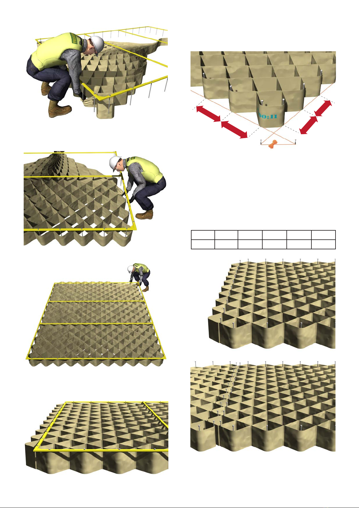
Stage 1 - Panel Placement
The base layer of any Prole 300 PAS 68 design is the
P300:11. Identify the panel by its label which can be
found on either end.
Once the correct Prole 300 is selected, build the
corresponding Prole 300 frame by following the Frame
Installation Guide and position it on your building
site with the long side along the direction of your
construction.
Next identify the female end of the Prole 300. The
female end of a P300:11 has 11 cells while the male end
has only 10 cells.
Start with the labelled corner of the female end, lift the frame
up and place the corner cell onto the two corner pins.
2
368mm
368mm
318mm
318mm
300:06 300:07 300:08 300:09 300:10 300:11
38 40 42 44 46 48
Work your way across, lift the frame slightly and push the
Profile 300 down under the pin and back up so the pin is
located inside the cell. Move along to the next cell and repeat.
Repeat the process along both sides.
Finish at the diagonally opposite corner ensuring that
the male cells at this end protrude halfway past the end
of the frame as shown below.
Using Pins
If the frame is not used the same can be achieved by
using pins.
Using a building line as a guide, pins can be placed into
the ground along the long sides of the construction at
368mm centres and across the ends at 318mm centres.
In the same way as when using a frame, the cells are
placed over the pins until the Prole 300 is tight and
symmetrical. Start with the labelled corner of the female
end then working along both sides and nish with the
male end.
Pin Quantities Required
Note: If you have more than one frame or sets of pins
available, it is recommended you set up more base units.
3

Stage 2 - Subsequent Panels
Ideally, several panels should be pinned out or framed at
anyonetime whichwillallow for thelling machine(front
end loader, excavator, etc.) to continue immediately to
the next panel, therefore keeping momentum of the
installation.
Using frames
Once the rst frame is in position the next frame is tted
with the Prole 300 and positioned in the direction of
construction, so that the male end on the rst frame
interlocks with the female on the second frame. This is
completed by butting the two frames together.
Using Pins
The same can be achieved using pins.
Once the rst Prole 300 is in position, the next Prole
300 is opened out and aligned in the direction of
construction, with the female end of the new Prole
300 interlocked with the male end of the rst. Pin out
the new Prole as previously until the Prole is tight and
symmetrical.
Stage 3 - Filling
Fill should be distributed evenly across the panel width
taking care not to dump ll in one area.
Even distribution of the ll and levelling with the
excavator will aid the compaction process and reduce
manual spreading.
Some manual leveling may be required with some ll
materials.
Once the panel is full and ready for compaction the
frame should be removed by carefully lifting. Use four
people, one on each side of the frame.
If using pins ensure that all are removed before
compaction.
4

D
O
N
O
T
E
N
T
E
R
T
H
I
S
A
R
E
A
Stage 4 - Compaction
Once the cells are lled (or slightly over lled depending
on ll material) the frame is removed and the ll
compacted. A mechanical plate compactor is ideal.
This can be carried out whilst the excavator is lling
the next frame however you must ensure that the
compactor does not enter into the excavator bucket
operating radius at any time.
Compaction of the material is achieved with three passes
of a plate compactor.
Note: Care must be taken not to over compact otherwise
the outer cell walls may be crushed which will aect the
overall cell/berm height.
If the level of ll is too high once compaction is complete
this must be removed before the next layer is laid.
Stage 5 - Subsequent Layers
Once the base level is complete or you have nished a
section (depending on your construction plan) move to
the next layer.
Using frame
First change the frame to the next size down as per the
frame guide. Place on the fabric panel as previously
instructed.
Position the frame on top of the layer below, checking
it is central to the berm. This will give you spacing of
160mm either side of the panel below or roughly half a
cell. Position the end directly in line with the layer below.
Using pins
Pins are placed in the outer cells of the lled layer.
Position them centrally in the cell and step back half
a cell (160mm) from the edge to achieve the desired
angle/prole required for the berm.
Note: It is recommended that sequential panels are laid
to maintain momentum of the lling process.
Panel joints. Prole 300 1.25m
Stagger panel joints by using half panels at each end of
the berm to create an interlock between the panels.
Note: Half panels are required on layers 2 and 4
5
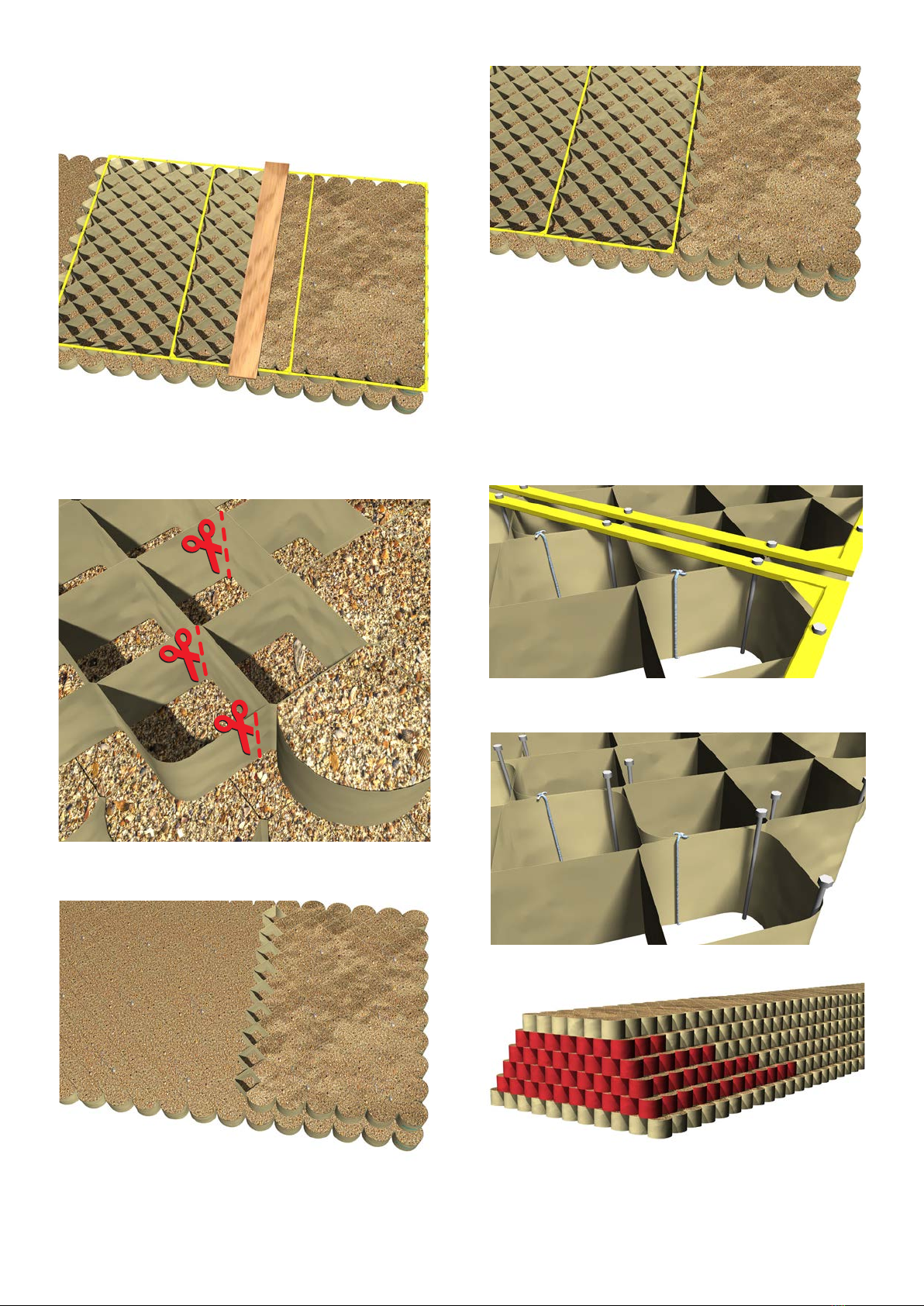
This is best achieved by carefully marking a line along
the centre of the panel, using a felt-marker or line-
paint, so you are left with complete cells in the same
conguration as a normal panel end.
It is advisable to cover the end cells with a scaold plank or
similar. Fill to the edge of the plank, leaving the cells below
the plank empty.
Then remove plank and cut cells next to the glue joints.
Remove the frame as usual and keep the unlled section
of Prole 300. Use this at the end of the run to complete
the layer.
Then place a new Prole panel on the frame and join to
the lled half panel.
Prole 300 1.50m
There are three distinct dierences between the Prole
300 1.25m high and the 1.50m high during construction;
1.The Prole 300 1.50m has an extra layer, using the
Prole 300:06 on top.
2. Connect all the end cells between panels with a cord
tied with a reef knot.
The same can be achieved when using pins.
3. Panel joints should be staggered by cutting the end
panels on each layer of a construction. Each layer should
be cut 1m shorter than the layer below to achive the
staggered joints.
6

Stage 6 - Landscaping
Once the berm is completed to the required specication
it can be landscaped.
The berm can be landscaped by topsoil being placed
on the front/rear face of the berm. Once this is done
the berm can be cut into the required angle using the
bucket of the excavator.
Note: Check the angle using a prole board set to the
required angle.
Berm Attack Face: - The granular material chosen for
the berm prole should be graded to between 54-57
deg. This should allow the berm to settle over time but
not below 50 deg. as required.
Top of Berm: - The nished berm level is to be minimum
of 1.25m or 1.50m above existing ground levels after
compaction depending on design.
Berm non attack face: - The granular material chosen
for the berm prole can be sloped at any angle required,
or as instructed by the Engineer on site.
To prevent erosion, the berm can be lined with seed
impregnated hessian with either grass seed/ wild grass
or turf can be laid. This will also allow it to blend in and
be more aesthetically pleasing.
End walls / walk ways and integration of Vehicle
Security Barriers (VSB)
During the construction of the berm, several things may
have been incorporated into the design:
• End berm wall
• Pedestrian aperture
• Integration with Vehicle Security Barrier
Pedestrian aperture can be installed within the berm but
must not be any closer than 10m from end of the berm
and a maximum of 1.2m wide.
Disclaimer
The information contained in this leaet is provided
by DEFENCELL (J & S Franklin Ltd or it’s aliates and
associates) in good faith. While DEFENCELL has made
reasonable eorts to ensure the accuracy, completeness
and appropriateness of such information, any reliance
on such information is entirely at the risk of the
party using it. The installation and conguration of
any of DEFENCELL’s products by a third party is not
DEFENCELL’s responsibility and DEFENCELL (or its
employees, distributors or contractors) shall not be liable
for any failure of any of DEFENCELL’s products caused by
improper installation or subsequent misuse.
7
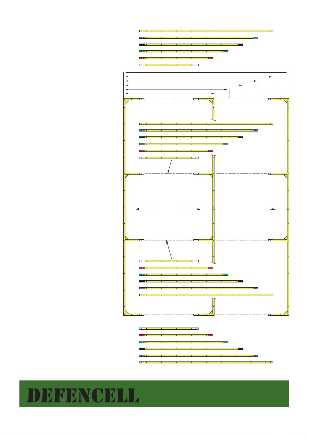
Prole 300 Universal Frame
Assembly Guide
1. The Prole Frame consists of four
corner pieces and six sets of four cross
pieces. The six dierent cross pieces
match the six dierent size Prole 300
panels and are colour coded.
The frame parts all have long pins pre-
tted which are inserted into the Prole
300 cells.
2. Assemble the two side bars using two
corner pieces on each side and connect
using the short nuts and bolts supplied.
3. Insert the four cross pieces (two end
and two centre) and connect using the
short nuts and bolts. The all yellow cross
pieces are used for the Prole 300:11.
4. For subsequent smaller Prole
panels, change the cross pieces to the
corresponding size.
5. After use, disassemble and clean the
frame and return to packing case.
11
10
9
8
7
6
PROFILE
6
7
8
9
10
11
PROFILE
11
10
9
8
7
6
6
7
8
9
10
11
JOINT LINE
JOINT LINE
PROFILE 6
PROFILE 7
PROFILE 8
PROFILE 9
PROFILE 10
PROFILE 11
Tel: +44 (0) 207 836 5746
email: info@defencell.com
www.defencell.com
DEFENCELL
© 2016 J&S FRANKLIN LTD. PROFILE 300 INSTALLATION V04/16


