Defro Home VITAL 37S User manual

operating manual
gas-fired convection room heater
DEFRO HOME VITA
37 S 51 S
BP B U C T
gas type
G2.350 G20 G27 G31 G30
translation of original operating manual
edition 1.b
May 2021
destination countries:
2
DEKLARACJA ZGODNOŚCI WE
DECLARATION OF CONFORMITY EC
nr 93/A-4/03/2021
DEFRO Spół a z ograniczoną odpowiedzialnością Spół a omandytowa
00-403 Warszawa, ul. Solec 24/253
Zakład produkcyjny:
2 -0 7 Strawczyn, Ruda Strawczyńska 103A
DEKLARUJE / DECLEARS
z pełną odpowiedzialnością, że produkt / with all responsibility, that the product
onwe cyjny ogrzewacz pomieszczeń opalany gazem / independent gas-fired convection heater
(typ/type)
DEFRO HOME VITAL 6,0 W
DEFRO HOME VITAL 5,5 W
typ urządzenia: C11, C31, C91
został zaproje towany, wyprodu owany i wprowadzony na ryne zgodnie z następującymi
dyre tywami:
has been designed, manufactured and placed on the market in conformity with directives:
GAR 2016/426/UE
i niżej wymienionymi normami zharmonizowanymi:
and that the following relevant Standards:
dokumentacja techniczna / technical documentation
PN-EN 613:2002
PN-EN 613:2002/A1:2004
PN-EN 17082:2020-03
PN-EN 437:2019-03
Wyrób oznaczono znakiem:
Product has been marked:
Ta de laracja zgodności traci swą ważność, jeżeli w urządzeniu wprowadzono zmiany, został przebudowany bez naszej zgody lub jest
użyt owana niezgodnie z instru cją obsługi. Niniejsza de laracja musi być prze azana wraz z urządzeniem w przypad u odstąpienia
własności innej osobie.
This Declaration of Conformity becomes invalid if any changes have been made to the device, if its construction has been changed without
our permission or if the device is used not in accordance with the operating manual. This Declaration shall be handed over to a new owner
along with the title of ownership of the device.
Urządzenie jest wy onywany zgodnie z do umentacją techniczną przechowywaną przez:
Device has been manufactured according to technical documentation kept by:
DEFRO Spół a z ograniczoną odpowiedzialnością Sp. ., Za ład produ cyjny: 26-067 Strawczyn, Ruda Strawczyńs a 103a.
Imię i nazwis o osoby upoważnionej do przygotowania do umentacji technicznej: Mariusz Dziubeła
ame of the person authorized to compile the technical documentation: Mariusz Dziubeła
Imię i nazwis o oraz podpis osoby upoważnionej do sporządzenia de laracji zgodności w imieniu producenta: Robert Dziubeła
ame and signature of the person authorized to compile a declaration of conformity on behalf of the manufacturer: Robert Dziubeła
Dwie ostatnie cyfry ro u, w tórym ozna owanie zostało naniesione: 21
Two last digits of the year of marking: 21
Warszawa, dn. 23.03.2021
miejsce i data wystawienia
place and date of issue.
Robert Dziubeła
prezes zarządu / CEO
3
Dear Customer,
We would like to thank ou for choosing the high qualit DEFRO
product which will ensure our safet and operational reliabilit .
As our customers, ou can alwa s count on the help of the DEFRO
Service Centre, which is read to ensure continuous efficienc of our
equipment.
Please note that in order to use the equipment safel and efficientl , it
is crucial to get familiar with the following directions.
Read and follow this Operating Manual - useful remarks
concerning proper operation of the equipment can be found
there.
Determine if all parts have been delivered or the fireplace was
not damaged during transport.
Check data on the rating plate against the warrant card.
Check whether the s stem is in compliance with the
recommendations of this manual and corresponding national
regulations before the start-up.
Basic usage rules are to be obe ed while using the equipment. It is
forbidden to remove the cover during operation of the equipment.
DEFRO Service Centre or Authorized DEFRO Service should be
alwa s contacted when an intervention is necessar because onl these
parties have original spare parts and are properl trained within the scope
of installation and operation of DEFRO products.
For our safet and equipment use convenience, please get
acquainted with this operating manual and send back a correctl filled cop
of the Warrant Card to the following address:
DEFRO Sp. z o.o. Sp. k
-
Centrum
Serwisowe
Ruda Strawcz ńska 103a
26-067 Strawcz n
@
serwis@defro.pl
B sending back our Warrant Card, ou will be registered in our
DEFRO products user’s database and we will be able to provide ou quick
and professional technical support.
If ou do not send back a correctl filled in Warrant Card and the
equipment qualit and completeness receipt within the period of up to two
weeks after the date of installation but no longer than within six months,
after purchasing, the warranty will become invalid! This results in dela s
with repairs and the necessit of covering costs of service and travelling
expenses.
Thank ou for understanding.
Yours sincerel ,
DEFRO Sp. o.o. Sp. k
Content of this Operating Manual is a propert of DEFRO sp. z o.o. Sp. k..
An cop ing, duplicating, publishing of content of this Manual
without prior written consent of DEFRO sp. z o.o. Sp. k. is forbidden.
Dear Customer,
We would like to inform ou that we make ever efforts to offer
products of qualit fulfilling the most restrictive standards and
warranting operational safet . All devices are produced in accordance
with the requirements of relevant EU directives and have CE safet
mark confirmed b the Declaration of Conformit EC.
We appreciate all our comments and proposals regarding our
level of service. We appreciate our comments and proposals
regarding our devices and the level of service provided b our
Partners and Technical Support and Service.
DEFRO Sp. o.o. Sp. K

4
TABLE OF CONTENTS
1. INFORMATION .......................................................................................................................................................................................... 6
2. BASIC SAFETY RULES ............................................................................................................................................................................. 6
2.1. Safet warnings ............................................................................................................................................................................... 6
2.2. Warnings related to operation ........................................................................................................................................................... 6
3. INTENDED USE ........................................................................................................................................................................................ 7
4. TECHNICAL SPECIFICATION ................................................................................................................................................................... 7
4.1. Design ............................................................................................................................................................................................. 7
4.2. Technical data ................................................................................................................................................................................. 8
4.3. Equipment ......................................................................................................................................................................................10
4.4. Fuel parameters..............................................................................................................................................................................10
4.5. Spare parts .....................................................................................................................................................................................10
5. TRANSPORT ...........................................................................................................................................................................................10
6. SYSTEM...................................................................................................................................................................................................10
6.1. Installation location .........................................................................................................................................................................10
6.2. Connection to the gas piping s stem ...............................................................................................................................................10
6.3. Connection to the concentric flue s stem .........................................................................................................................................11
6.3.1. Horizontal outlet of concentric pipe - t pe C11 ............................................................................................................................11
6.3.2. Vertical outlet of concentric pipe - t pe C31 ................................................................................................................................12
6.3.3. Outlet using conventional flue - t pe C91 ....................................................................................................................................12
6.4. Terminals .......................................................................................................................................................................................12
6.5. Installation of control s stem ...........................................................................................................................................................12
6.6. Adjustment .....................................................................................................................................................................................13
6.6.1. Adjustment of flame in the control burner ....................................................................................................................................13
6.6.2. Adjustment of gas exhaust pressure ...........................................................................................................................................13
6.6.3. Adjustment of minimum height of flame of the primar burner ......................................................................................................13
6.6.4. Final operations .........................................................................................................................................................................14
6.7. Tightness control of the balanced flue s stem ..................................................................................................................................14
6.8. Flue gas flow damper adjustment ....................................................................................................................................................14
6.9. Conversion to the other gas ............................................................................................................................................................15
6.10. Installation of the heater ..................................................................................................................................................................15
6.11. First start-up ...................................................................................................................................................................................15
7. OPERATION ............................................................................................................................................................................................16
7.1. Safet rules ....................................................................................................................................................................................16
7.2. Preparation .....................................................................................................................................................................................16
7.3. Information .....................................................................................................................................................................................16
7.4. Deactivation of remote control function ............................................................................................................................................16
7.5. Activation of remote control function ................................................................................................................................................16
7.6. Control of FIREPLACE with a remote control ...................................................................................................................................16
7.6.1. Setting temperature units ...........................................................................................................................................................16
7.6.2. Time settings .............................................................................................................................................................................17
7.7. Parental lock ...................................................................................................................................................................................17
7.7.1. Firing up in manual mode ...........................................................................................................................................................17
7.7.2. Standb mode ...........................................................................................................................................................................17
7.7.3. Fireplace shutdown ....................................................................................................................................................................17
7.7.4. Adjustment of flame height .........................................................................................................................................................17
7.7.5. Adjustment of limit heights for the flame......................................................................................................................................17
7.7.6. Timer.........................................................................................................................................................................................18
7.7.7. Operating modes .......................................................................................................................................................................18
7.7.8. Thermostatic mode ....................................................................................................................................................................18
7.7.9. Program mode ...........................................................................................................................................................................19
7.7.10. Eco mode ..................................................................................................................................................................................19
7.7.11. Behavior of FIREPLACe when there is no signal from the remote control ....................................................................................19
7.8. Power suppl and batter replacement ............................................................................................................................................20
7.8.1. Batter replacement in the remote control ...................................................................................................................................20
7.8.2. Batter replacement in the receiver ............................................................................................................................................20
7.9. Manual control of fireplace ..............................................................................................................................................................20
7.9.1. Firing up ....................................................................................................................................................................................20
7.9.2. Damping a flame of the primar burner .......................................................................................................................................20
7.9.3. Fireplace shutdown ....................................................................................................................................................................20
7.9.4. Error codes ................................................................................................................................................................................21
8. Decorative items .......................................................................................................................................................................................23
8.1. Components of ceramic chunks set .................................................................................................................................................23
8.2. Assembl of ceramic chunks ...........................................................................................................................................................24
8.3. La ing of decoration imitating the stones .........................................................................................................................................32
9. MAINTENANCE AND SERVICE................................................................................................................................................................33
9.1. Window panel cleaning ...................................................................................................................................................................33
9.2. Window panel dismantling ...............................................................................................................................................................33
9.3. Periodic maintenance inspection .....................................................................................................................................................34
10. EMERGENCY PROCEDURES .................................................................................................................................................................34
10.1. When the gas odour is stated ..........................................................................................................................................................34

5
10.2. Flue gas escape .............................................................................................................................................................................34
10.3. Carbon monoxide escape................................................................................................................................................................34
11. TROUBLESHOOTING ..............................................................................................................................................................................34
12. REMOVAL DUE TO WEAR-OUT ..............................................................................................................................................................34
13. PRODUCT WARRANTY TERMS AND CONDITIONS ................................................................................................................................35
13.1. Warrant conditions “48h Service” ...................................................................................................................................................36
14. WARRANTY CARD ..................................................................................................................................................................................37
15. CARRIED OUT WARRANTY REPAIRS AND MAINTENANCE. ..................................................................................................................38
16. WARRANTY CARD /cop to send back/ ....................................................................................................................................................39
17. COMPLAINT FORM ..................................................................................................................................................................................41
18. COMPLAINT FORM ..................................................................................................................................................................................43
19. COMPLAINT FORM ..................................................................................................................................................................................45
20. REGISTER OF INSPECTIONS OF SMOKE DUCTS..................................................................................................................................47

6
1. INFORMATION
Operating manual is an integral and essential part of the product
and must be forwarded to the user also in case when the propert is
transmitted. User should carefull read the manual and save it for the
future because all remarks included there are important guidelines
concerning safet during installation, usage and maintenance.
Installation of the equipment must be carried out in accordance
with the mandator standards in the countr of destination, according
to guidelines of the manufacturer and b qualified personnel. Improper
installation of the device can be a reason for personal injuries and
damage to propert , for which the manufacturer is not liable.
The equipment can be used onl for the purpose it was explicitl
intended. An other use should be treated as inappropriate and in
consequence as dangerous.
In case of error during installation, usage or maintenance works
caused b non-observance of the legislation, regulations in force or
instructions contained in this manual (or others, delivered b the
manufacturer) the manufacturer rejects an contractual or non-
contractual liabilit for resulting damages and the warrant for the
device becomes void.
Versions of the publication
Due to continuous improvement of the product, DEFRO reserves
the right to update this publication without prior notice.
The content of this Operating Manual is a propert of DEFRO. An
cop ing, duplicating, publishing of content of this User’s Manual without
prior written consent of DEFRO is forbidden.
Manual storage and browsing its contents
We recommend taking care of this manual and store it in an easil
and quickl available location. If this manual has been lost, damaged
or destro ed, ou should request a cop in the sales outlet or directl
from the Manufacturer providing identification data of the product. All
the most important information included in the operating manual are
marked with “bold” and have s mbols pointing out user’s attention to
hazards which can be present during operation of the gas-fired heater.
S mbols used in the text are explained below:
Danger!
Direct threat to life and health! Non-compliance with the
recommendations marked in this way and misuse may
result in death or major injuries.
Danger!
Danger from electrical voltage! Incorrect installation and
incorrect electrical connections may cause danger to life
by electric shock.
Note!
Warning symbol indicating that you should read carefully
and understand the given information to which it relates.
Non-compliance with this recommendation may result in
major damage to the equipment and create a hazard for
the user or the environment.
Danger!
Warning symbol indicting hazard to health resulting from
the action of high temperature! Non-compliance with the
recommendations distinguished in this way may cause a
fire or burns.
Hint!
Informative symbol. Useful information and hints are
marked in this way.
2. BASIC SAFETY RULES
2.1. SAFETY WARNINGS
The national and local provisions should be met.
Equipment should be installed in compliance with the
legal standards applicable in the given location, region
or countr .
The equipment should be used b a person
(including
children) of impaired ph sical, sensor , mental
capabilities and b persons without experience and
required knowledge provided that such operation is
not carried out under their supervision or after prope
r
instruction b a person responsible for their safet .
You should alwa s observe the guidelines given in the
operating manual to ensure correct use of the
equipment and to prevent accidents.
Operation and adjustment should be carried out b
adults. Errors
and incorrect setting can cause
hazardous situations and/or incorrect operation.
Prior to an operations,
the user (or an person
operating the equipment) should read and understand
the whole contents of this manual.
Equipment should be used onl as
intended. Each
other use is considered as misuse and hazardous as
a consequence.
In case of disturbances in operation,
the equipment
can be restarted onl when the occurred problem has
been removed and the equipment is brought back to
original condition.
T
he user is full responsible for misuse of the product
and relieves DEFRO from an civil and criminal
liabilit .
All t pes of modifications or replacement of equipment
parts with non-
original components or without
authorization ma present a risk for opera
tor and
relieves DEFRO from an civil and criminal liabilit .
Incorrect installation or maintenance (incompatible
with contents of this manual), can cause injuries of
people, animals or propert damage. Then DEFRO
shall be relieved of an civil or criminal liabilit .
All surfaces of the equipment are working surfaces
and some of them is ver hot. You should avoid direct
contact with such components.
Keep children awa from the equipment when it is
operating because each hot surface can cause burns.
2.2. WARNINGS RELATED TO OPERATION
Equipment should be shutdown in case of failure or
incorrect operation.
Gaseous fuel used in the equipment should meet
the
conditions described in this manual.
Equipment should be installed in rooms with fire
protection and
equipped with all required components
such as suppl (with air) and flue gas discharge.
The equipment should be stored in the rooms free
from moisture and the cannot be exposed to adverse
effects of the weather.
The equipment consumes as much air as it i
s required
for the combustion process.
Do not touch the equipment with wet or moist parts of
the bod and/or barefooted.
Disconnect the equipment from the electric grid
before the cleaning.
ADDITIONAL INFORMATION
7
In case of an
problems,
ou should contact sales
outlet or qualified personnel authorized b DEFRO.
Request original spare parts if the repair is necessar .
Use onl gaseous fuel with properties compatible with
the recommendations of this operating manual.
Check and clean flue g
as discharge ducts (connecting
piece to flue) periodicall .
Store this manual carefull because it should be
available for a whole period of equipment operation.
In case of sale of giving the equipment to the other
user ou should alwa s make sure whether
the
product has the manual enclosed.
Request new cop from authorized sales outlet in
DEFRO compan if it has been lost.
3. INTENDED USE
The room heater is intended for combustion of natural gas (NG) or,
after proper adaptation, propane-butane (LPG) gas, to heat the rooms
where it has been installed.
Gas-fired room heater can be connected multiple times.
4. TECHNICAL SPECIFICATION
4.1. DESIGN
The bod of the heater is made of steel sheet with combustion chamber located inside and lined with additional panels made of sheet (rear and
sides).
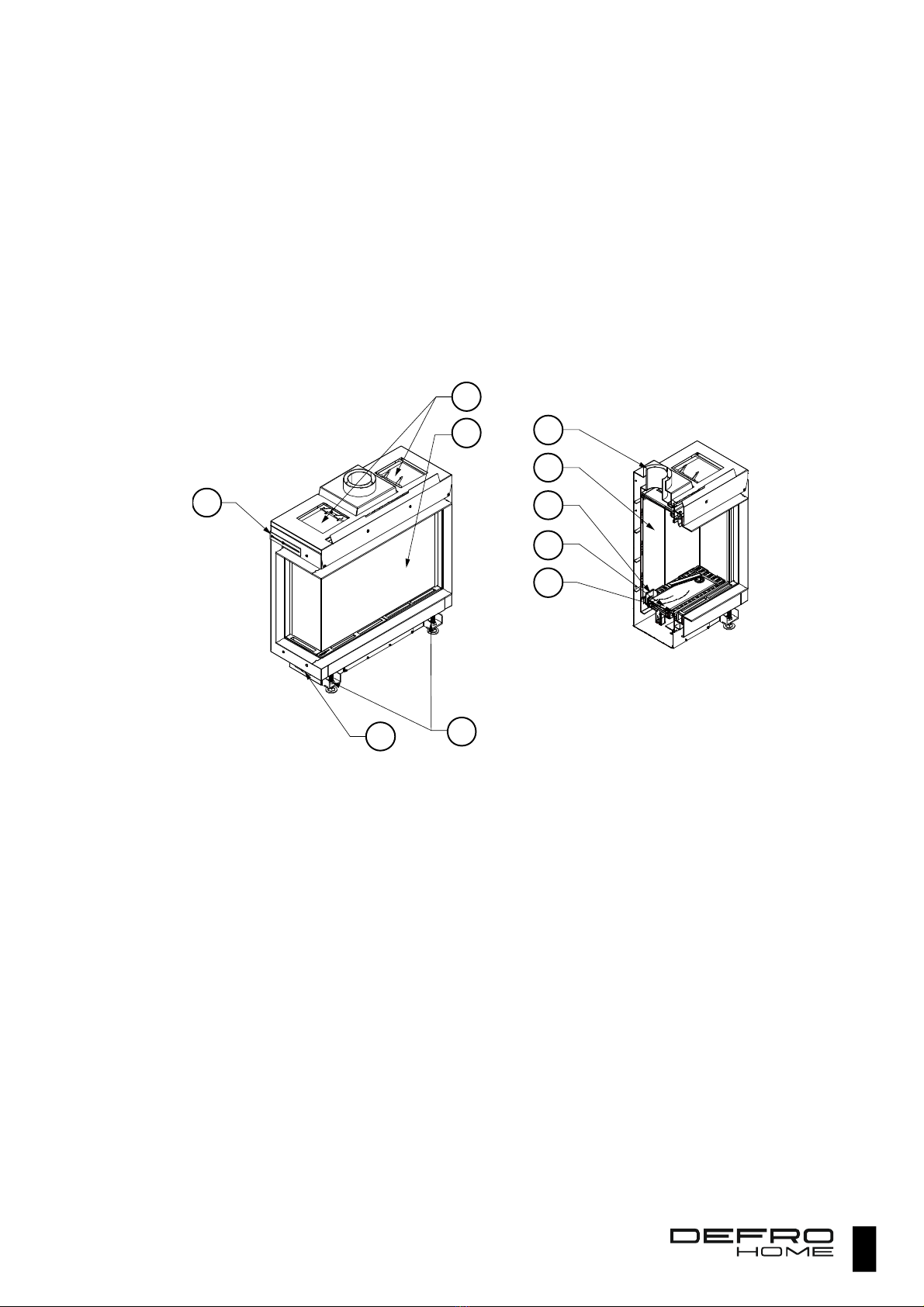
Picture 1 Design of DEFRO HOME VITAL heater.
1 - explosion relief vents, 2 - window panel, 3 - end cap of gland for gas lines, 4 - adjustable feet, 5 - flue, 6 - panels of combustion chamber, 7 - set of
control burner, spark igniter and temperature sensor, 8 - primar burner, 9 - combustion air inlets.
The gas burner supplied with gas and air is located in the floor of the chamber. Gas is supplied from the electronic controlled dosing device GV60,
which is connected to the gas piping s stem. Gas is combusted after initiation of ignition b the spark igniter, which initiates ignition of the ignition burner.
The main burner is started after detection of ignition flame. Flue gas is exhausted through the concentric connector to twin-walled concentric coaxial pipe
(internal pipe). The same pipe (external pipe) is used to suppl air required for combustion. The fireplace is operated b a remote control, which is part
of the control s stem manufactured b Mertik Maxitrol GV60.
1
2
34
7
5
6
8
9
9
8
4.2. TECHNICAL DATA
Table 1. Technical data of DEFRO HOME VITAL heater.
Parameter Unit Reference gas
G20 G27 G2.350 3P 3B/P
Nominal connection pressure, pnom mbar 20 20 13 29 / 37 / 50 29 / 37 / 50
Rated maximum heat load acc. to Hi, Qznam(max) kW 6.0 6.0 6.0 5.5 5.5
Rated minimum heat load acc. to Hi, Qznam(min), kW 3.6 3.6 3.6 3.3 3.3
Controller - gas pressure regulator locked gas pressure regulator in operation
Gas pressure downstream of the controller for Qznam(max), preg_Qznam(max) mbar 12.2 12.2 6.8 29.7 29.7
Gas pressure downstream of the controller for Qznam(min), preg_Qznam(min) mbar 4.0 3.4 2.3 12.0 12.0
Stream of consumed gas (15 °C, 1013 hPa) for Qznam(max), V_Qznam(max) m3/h 0.626 0.774 0.881 0.225 0.170
Stream of consumed gas (15 °C, 1013 hPa) for Qznam(min), V_Qznam(min) m3/h 0.376 0.464 0.529 0.135 0.102
Equipment efficienc class - 1 2 2 1 1
NOX emission class2 37 - 4 4 3 4 4
51 - 3 4 3 4 4
Diameter of gas nozzle of the main burner mm 2.00 2.40 3.25 1.45 1.35
Diameter of concentric coaxial pipe mm 100/150
Gas control valve GV60
Receiver suppl V DC 6
Weight1 kg 90 90 90 90 90
1) Device weight depends on selected design version and its equipment.
2) Level for C11 equipment acc. to PN-EN 613:2002/A1:2004.
Table 2. Technical data of GV60 regulator with a receiver and remote control manufactured by Mertik Maxitrol.
Parameter Unit Value
Directives fulfilled - 2009/142/ECC, DIN EN 298, DIN EN 126, DIN EN 14611
Fuel - gas of first, second or third famil acc. to EN-437
Adjustment range - class C acc. to EN 88
Adjustment range for pressure regulator mbar 5÷40
Maximum input pressure mbar 50
Allowable operating temperature for GV60 valve ºC 80
Allowable operating temperature for receiver supplied with batteries ºC 55
Allowable operating temperature for receiver supplied from electric power
s stem
ºC 80
Allowable operating temperature for remote control ºC 60
Allowable operating temperature for ignition cable ºC 150
Connection of main gas inlet inch reduction nipple ½″
Connector of control burner mm 6 mm
Mounting position vertical or within the angle from 0° to 90º from vertical position
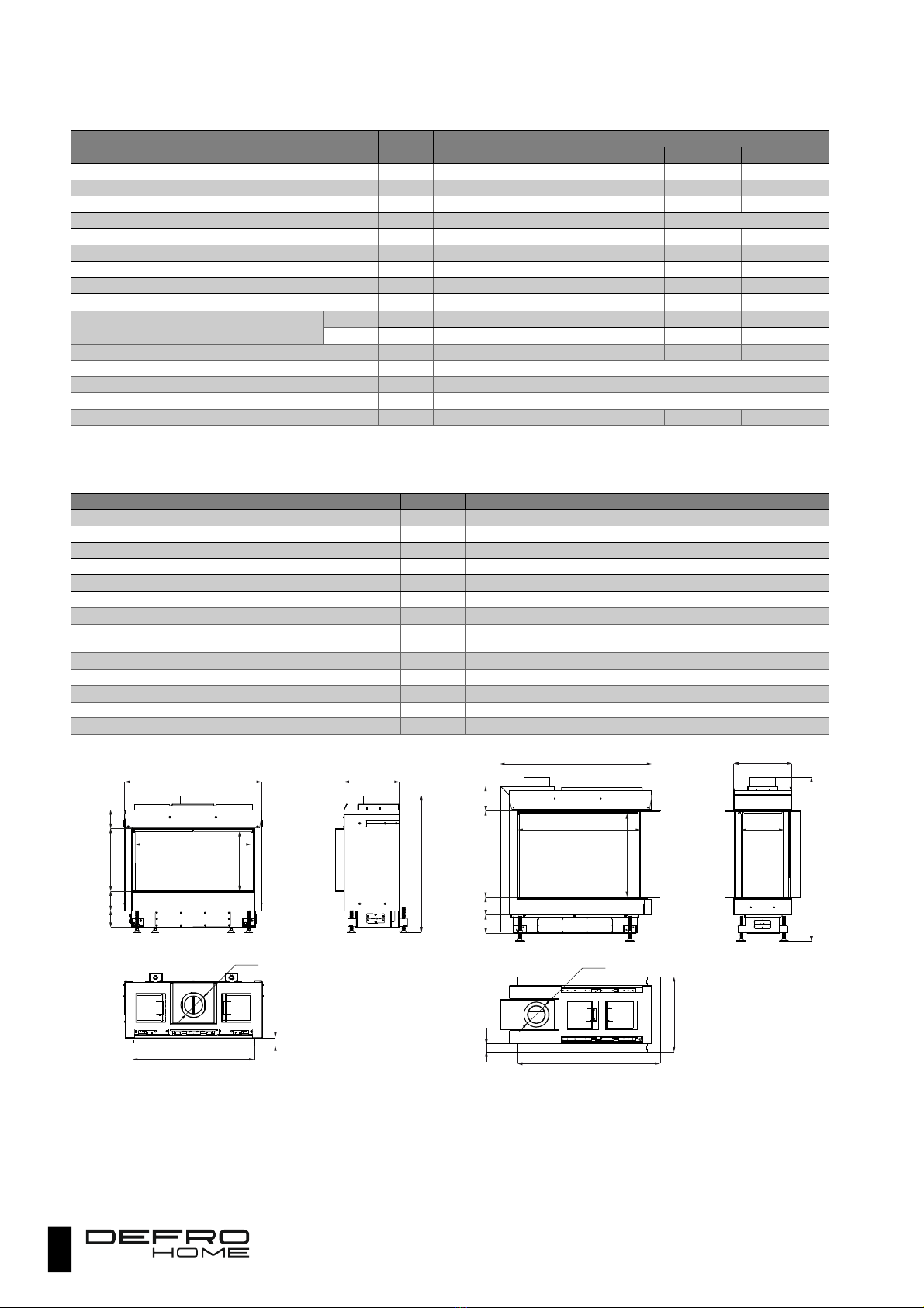
Picture 2. Dimensions of DEFRO HOME VITAL 37 S.
Picture 3.3 Dimensions of DEFRO HOME VITAL 37 S U.
720
47
>808
3
2
9
Ø150
8
1
2
3
7
0
1
1
5
9
8
1
1
1
687
350
845
51
>967
3
4
2
Ø150
8
9
6
443
5
1
2
1
0
3
1
0
8
1
4
6
717
490
242

9
Picture 4.4 Dimensions of DEFRO HOME VITAL 37 S C.
Picture 5 Dimensions of DEFRO HOME VITAL 37 S T.
Picture 6 Dimensions of DEFRO HOME VITAL 37 S BP and DEFRO
HOME VITAL 37 S BL (mirror reflection of BP version).
Picture 7. Dimensions of DEFRO HOME VITAL 51 S U.
Picture 8. Dimensions of DEFRO HOME VITAL 51 S T.
Picture 9 Dimensions of DEFRO HOME VITAL 51 S.
983
47
808
3
3
0
2
9
7
Ø150
8
8
3
3
7
0
1
1
5
9
8
1
1
1
783 188
350
8
2
8
3
0
9
>781
3
7
0
1
0
7
9
8
1
5
4
720
404
47 Ø150
4
7
700
360
8
4
8
741 247
3
2
9
>823
3
7
0
1
1
5
9
8
1
1
2
350
850
297
49 Ø150
4
9
845
51
>827
3
4
2
Ø150
8
9
7
444
3
7
2
1
0
3
1
0
8
1
4
6
717
350
242
8
2
8
3
0
9
>918
5
1
0
1
0
7
9
8
1
5
4
720
403
47 Ø150
4
7
4
7
707
506
Ø150
720
3
3
2
>962
8
1
3
919
47
5
1
0
1
1
5
9
8
1
1
2
675
490

10
Picture 10. Dimensions of DEFRO HOME VITAL 51 S BL and DEFRO
HOME VITAL 51 BP (mirror reflection).
Picture 11. Dimensions of DEFRO HOME VITAL 51 S C.
4.3. EQUIPMENT
The gas-fired heater is delivered on a pallet, foil-wrapped and are
full assembled. Scope of deliver can include additional components
and subassemblies, according to the order of the user. Standard
components of the equipment are specified in the table 2.
Table 3. Equipment of DEFRO HOME VITAL room heater.
Standard equipment of gas fireplace Unit Quan
tity
Equipment operating manual pcs. 1
Operating manual and warrant card for electronic
controller
pcs. 1
Controller with a valve set 1
4.4. FUEL PARAMETERS
Gaseous fuel of second or third famil acc. to the EN 437 standard
is used as a primar fuel for the DEFRO HOME VITAL heater.
The heater is factory adapted to one type of fuel acc. to the
customer’s order and can be operated only with this fuel.
Conversion of the equipment to the other type of fuel and
change of gas on your own and without conversion is
forbidden!
Contact the manufacturer if it is required to change a fuel
type.
4.5. SPARE PARTS
To obtain information on availabilit of spare parts for gas-fired
fireplace or inquiries about equipment servicing please contact with
DEFRO Service Center or Authorized DEFRO Service.
DEFRO Sp. o.o. Sp. k
Centrum Serwisowe
Ruda Strawc yńska 103a
26-067 Strawc yn
@
serwis@defro.pl
5. TRANSPORT
Room heater in the packing material should be transported in the
horizontal position using a special trolle . In special cases and on short
distances, it is allowed to transport it in vertical position.
6. SYSTEM
Chec the local conditions for distribution before
installation (identify type of gas and its pressure) and
whether the current settings of a heater are correct.
VITAL heater should be supplied with the same type of gas
as the other gas-fired equipment (if any) in the home of their
installation.
Installation of the gas-fired heater should be performed b qualified
personnel. All assembl operations should be performed in accordance
with the applicable national and local regulations within the scope of
fire protection, requirements of gas distributor and local authorities.
Gas s stem and flue gas handling s stem should be in compliance
with the Regulation of the Minister of Infrastructure of 12.04.2002
(Journal of Laws of 2002, no. 75, item 690) with all subsequent acts
amending this regulation.
Obtain all necessar consents from the appropriate authorities
before the installation: Regional gas compan , chimne sweeping
compan and building administration.
6.1. INSTALLATION LOCATION
Selection of installation location of the gas-fired heater should be
based on meeting of the following conditions:
access to gas piping s stem should ensure ease of
connection; flexible hoses should not be excessivel twisted;
access to chimne s stem should ensure as low number of
bends as possible;
Distance of the heater from non-flammable components of
the housing should not be smaller than 80 mm and
temperature of walls exposed to direct heating b the heater
should not exceed 80 ⁰C.
The room heater is intended for installation onl in vertical position
and should be placed on hard and non-flammable substrate with
suitable load-carr ing capacit . It is forbidden to install the heater as a
unit hanging on the wall!
6.2. CONNECTION TO THE GAS PIPING SYSTEM
The device is intended only for one type of fuel acc. to the
customer’s orders indicated on the first page of the manual
and declaration on the rating plate.
8
4
8
9
4
9
835
510
850
297
49 Ø150
3
2
9
741247
490
989
50
>963
3
3
0
2
9
7
Ø150
8
8
9
5
1
0
1
1
5
9
8
783 189
500
11
Heater connection to the gas system should be in
compliance with the applicable regulations.
Shut off the gas inflow using main valve before
commencing the installation wor s.
Before installation ma e sure that the gas meter has
suitable throughput, also in case when the other
equipment is drawing the gas.
During installation ma e sure to avoid getting of dirt
(dust, water and others) into the gas duct. It is
recommended to install the filter.
Install a gas shut-off valve for the heater.
If not stated otherwise b the local regulations, then gas ducts
should be led outside the wall. It is indicated to install a filter, stopping
the possible contaminants from the gas s stem, on the gas suppl duct.
Check tightness after installation.
To connect the heater to the gas piping s stem, it is required to
remove:
Glazing - description of removal is given in 9.2,
covers of cleanouts in base of the heater.
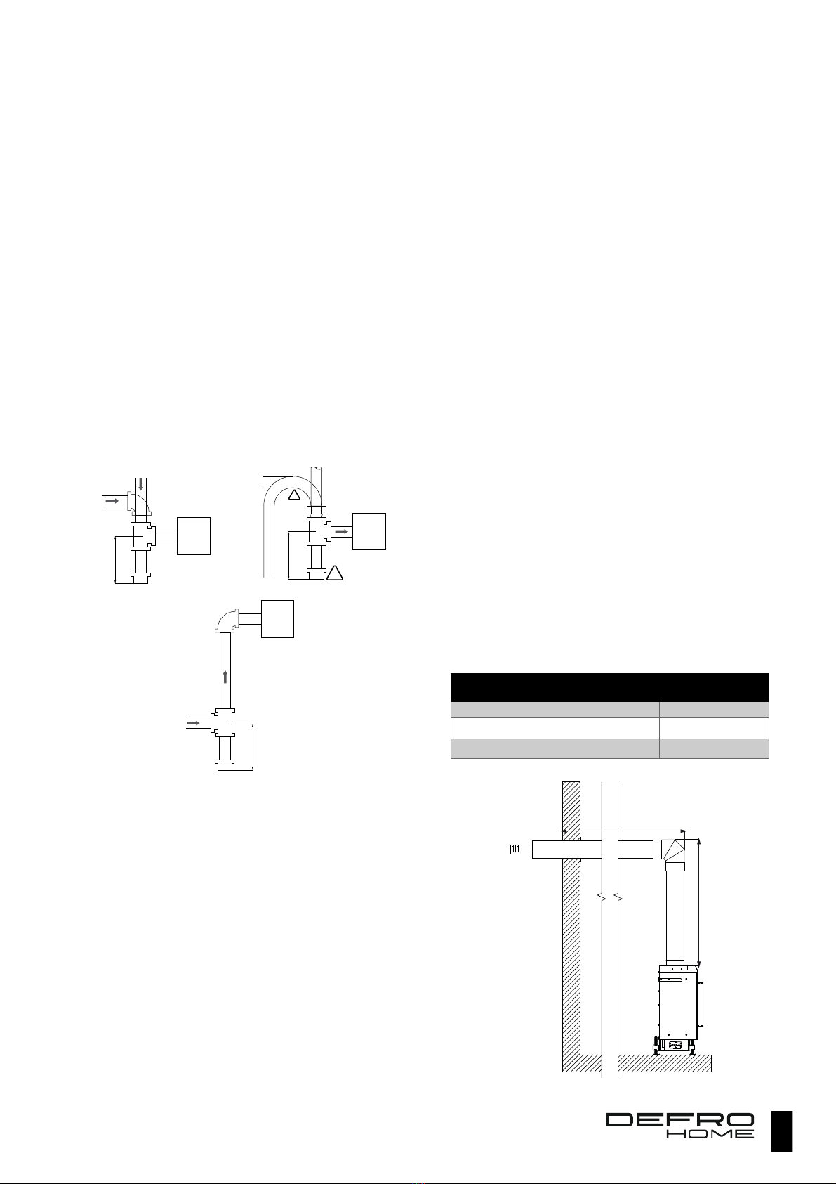
Install sedimentation trap (acc. to the picture) if it is required to
ensure protection against dirt in the gas piping s stem.
Picture 12 Method of installation of sedimentation trap if required.
GV60 valve with receiver should be located in the box intended for
this purpose. Conditions for cabinet installation
Cabinet should be located in a distance allowed b the
cables of spark igniter and thermocouple. Do not extend
these cables!
Cable of spark igniter should be led awa from the metal
parts,
Cabinet should be located in a location free from moisture,
dust and corrosive agents!
The cabinet should be installed in a location where
temperature does not exceed 25 ºC.
6.3. CONNECTION TO THE CONCENTRIC FLUE SYSTEM
The room heater is adapted for removal of flue gas and uptake of
air for combustion through the concentric flue s stem with a diameter
150/100 mm.
Please note the following rules:
Outlet-aspirating duct should protrude b min. 18 mm from
the wall.
Installation of elbow 90⁰ results in reduction of total
allowable length of the pipe b 2 meters.
Installation of elbow 45⁰ results in reduction of total
allowable length of the pipe b 1 meter.
First elbow connected to the equipment is not taken into
consideration.
Verticall lead pipes should be fixed to the wall using
brackets arranged in approx. 1-meter distance.
Start leading from the chimne side using vertical duct of
length not smaller than 1 metre.
The wall connector is counted as 1 m.
Execute thermal insulation of all flammable walls at the
distance min. 25 cm from the chimne s stem.
Ensure additional 5 cm of clearance between the wall and
duct for flammable walls. Fill the space with thermal
insulation.
Maximum length of chimne s stem should not exceed 10
metres.
Install condensate discharge s stem from the chimne
s stem, e.g. as droplet eliminator, if necessar .
End vertical sections with terminal should be led with 1%
slope towards the outside of the building to prevent flowing
of possible condensate to inside the fireplace.
Concentric coaxial pipe should be ended with a suitable
wind protection cap. For horizontal pipes (led through the
wall) it is required to use (t pe C11) special horizontal cap,
while for vertical variant (led through the roof) - vertical cap
(t pe 31).
6.3.1. HORIZONTAL OUTLET OF CONCENTRIC PIPE - TYPE
C11
It allows removing the flue gas and air intake b horizontal section
of the coaxial pipe led through the wall of the building. Minimum length
of vertical section should be 1 m and length of horizontal section
depends on length of vertical section, but should not exceed 3 m. It is
allowed to use onl one elbow 90 in the s stem. Remember about
suitable slope of the end horizontal section (see previous chapter). A
diagram of C11 t pe outlet is presented on picture 13.
Table 4. Total lengths of C11 type concentric coaxial pipe depending
on minimum length of vertical section.
Total length
of the balanced flue system Dn100-150 Lmin
2.8 m 1 m
10.5 m 2 m
13.9 m 3 m
Picture 13. Diagram of horizontal outlet of concentric pipe – type C11.
level
min 76 mm
s
l
o
p
e
suppl from
gas piping s stem
sediment trap
gas
regulator
level
vertical
min 76 mm
s
l
o
p
e
gas suppl
sediment
trap
gas
regulator
!
1
vertical
min 76 mm
suppl from gas
piping s stem
sediment
trap
gas
regulator
L min 1 m
P max 3 m

12
6.3.2. VERTICAL OUTLET OF CONCENTRIC PIPE - TYPE C31
Concentric pipe is led through the roof or floor slab of the building.
Minimum distance of the vertical section without an elbow is 1 m and
maximum 10 m. Total length of the pipe should not exceed 10 m.
Picture 14. Diagram of outlet of C31 concentric pipe.
6.3.3. OUTLET USING CONVENTIONAL FLUE - TYPE C91
Picture 15. Diagram of outlet of C91 concentric pipe.
This s stem ma use a conventional chimne to remove the flue
gas and for air intake. A pipe with suitable terminal at the outlet is
installed inside the flue and used for this purpose, while flue space
outside the pipe is used for air intake. However, the following conditions
should be fulfilled:
Diameter of flue gas exhaust pipe inside the chimne is 100
mm, its maximum length should not exceed 6 m.
Chimne section should not be lower than 150mm x 150mm.
Flue should be tight, with full flow capacit , clean and eas to
maintain.
Chimne outlet of the existing chimne in connection with a
terminal should be protected against flooding or clogging and
the terminal should be installed in a wa ensuring its correct
operation.
Penetration of concentric pipe through the wall to the
chimne should be equipped with a trim plate.
6.4. TERMINALS
Concentric coaxial pipe should be ended with a suitable terminal
corresponding to the t pe of s stem. Below ou will find terminals for
C11 and C31.
C11 t pe terminal. Designation: A – 151.6, B – 240.
C31 t pe terminal. Designation: A – 97.5, B - 202, C- 228.
C91 t pe terminal.
6.5. INSTALLATION OF CONTROL SYSTEM
The installation should be carried out according to the manual of
control s stem manufactured b Mertik compan and the
recommendations given in this chapter. The GV60 gas valve with
equipment manufactured b Mertik is the onl one intended for
installation in the DEFRO HOME VITAL heater. S stem can be
installed onl in the brand-new fireplace.
During installation, ou should observe the below pictures
presenting the arrangement of the connecting and control components
of the GV60 valve and receiver s stem.
max 10 m
min 1 m
L
max 6 m
kolano 45º
rozeta
H
13
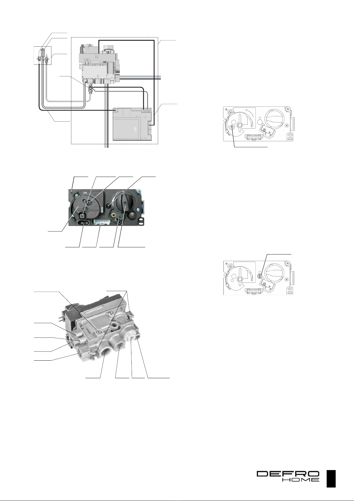
Picture 16. Connection diagram of the GV60 controlled valve with the
other components of the control system.
Picture 17 Arrangement of control components at the GV60 valve.
Attention!!!
The ON/OFF switch is an optional equipment and ma not be used in
the delivered equipment!
Picture 18 Arrangement of connectors at the GV60 valve.
The GV60 valve should be installed verticall or in a position
deviated from the verticalit to 90 degrees. Do not install it in a position
reversed b 180 degrees (upside down).
Unused gas inlets or outlets should be
tightly plugged!
6.6. ADJUSTMENT
The heater is factor adapted for the given t pe of fuel according
to the customer’s order. Also pressure adjustment for exhaust gas for
the pressure regulator is made acc. to the given t pe of gas. The task
of the fitter, after installing the chimne , is to check the settings and
make possible corrections to ensure that pressure values for the given
t pe of fuel corresponds to table 1 for both rated loads (minimum and
maximum).
6.6.1. ADJUSTMENT OF FLAME IN THE CONTROL BURNER
The control flame is factor set to the maximum height. To
decrease it:
Set manual mode knob to ON
Pierce the membrane protecting the alignment screw with a
screwdriver
Decrease the flame turning the screw clockwise
Picture 19 Location of screw for adjustment of flame height in the
control burner.
6.6.2. ADJUSTMENT OF GAS EXHAUST PRESSURE
Remove blanking plug from exhaust pressure measurement
opening in the GV60 valve.
Connect a pressure gauge to the measuring point.
Set the main valve knob to ON.
Remove the plastic cap from the screw of pressure regulator.
Adjust the pressure of the primar burner b turning the
screw; clockwise rotation increases the pressure.
When the adjustment has been completed ou should protect
the following fixtures with blanking plugs: pressure control
screw and, after removal of pressure gauge, the opening for
measurement of exhaust pressure.
Picture 20. Location of adjustment screw for gas exhaust pressure.
If there are no effects of adjustment - check exhaust pressure b
connecting the pressure gauge to measuring opening intended for this
pressure. Depending on the measurement, ou should:
If the inlet pressure has a correct value - probabl the valve
is damaged and it should be replaced.
If the inlet pressure is too low - ou should restore the correct
pressure taking the appropriate measures (check the s stem,
contact the gas supplier).
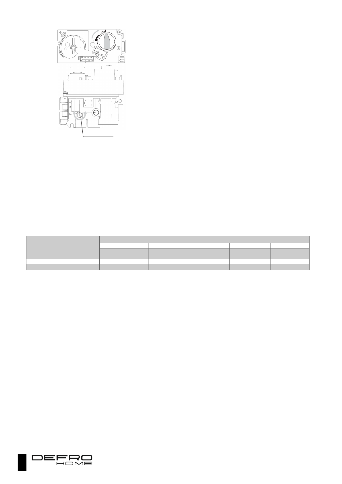
6.6.3. ADJUSTMENT OF MINIMUM HEIGHT OF FLAME OF THE
PRIMARY BURNER
Set the main valve knob to OFF.
Turn the knob clockwise until the valve is open.
Reduce the minimum height of flame of the main burner to
the required value b turning the adjusting screw to the right.
Factor set, minimum height of flame of the main burner is
set to maximum value.
GV60
valve
Receiver
palnik kontroln
control
burner
unit
s
p
a
r
k
i
g
n
i
t
e
r
GV60 valve
and receiver box
8-wire conduct
of receiver
igniter
suppl wire
arrester
gas piping s stem
main burb\ner suppl
ON(I)/OFF(○)
switch
c
o
n
t
a
c
t
of piezoelectric
igniter
2,8x0,8
button
of piezoelektric
igniter
m
a
n
u
a
l
control
of control
burner
pressure
regulator
blanking plug
8-pin
socket
of receiver
mikro-
przełącznik
main
valve
knob (in OFF position)
manual
control
knob
g
as inlet
gas inlet
thermal
flame
arrester
control
burner connector
i
nlet pressure
m
easurement
o
utlet pressure
m
easurement
r
e
g
u
l
a
c
j
a
p
ł
o
m
i
e
n
i
a
p
alnika głównego mounting holes
gas outlet
gas outlet
control flame adjustment screw
ON
MAN
a
d
j
u
s
t
m
e
n
t
s
c
r
e
w
for gas outlet pressure
ON
MAN
14
Picture 21 Position of knob of the main valve and location of screw for
adjustment of main flame.
6.6.4. FINAL OPERATIONS
After connection and making the necessar adjustments ou should:
Check tightness of executed gas connections using a special
detector and, if there are an leaks, shut off the gas suppl
and make these connections once again.
Connect power suppl of the receiver b inserting four AA
batteries.
6.7. TIGHTNESS CONTROL OF THE BALANCED FLUE SYSTEM
After installation of the balanced flue s stem and when the heater
is read for operation, ou should start the equipment at maximum heat
load. Perform measurement of CO2 in the combustion air suppl duct
using flue gas anal ser. If there is no indication of carbon dioxide
presence in the combustion air it means that concentric coaxial pipes
are correctl installed.
6.8. FLUE GAS FLOW DAMPER ADJUSTMENT
After installation of concentric coaxial s stem (acc. to allowed configuration for ducts leading) set the flue gas flow damper in half of opening
position.
Close the window panel and set maximum load of the heater.
Measure ox gen content after 5 minutes.
If the ox gen content deviates from this given in the table, then ou should close the gas suppl to the main burner, leaving the flame of the
control burner.
If the ox gen content is higher than this given in the table, ou should close the opening of flue gas flow damper; if it is lower - increase opening
of flue gas flow damper.
Restore the flame of main burner to maximum value and measure content of ox gen in flue gas.
If the absolute value between the measured content of ox gen in flue gas and the value given in the table does not exceed 0.3% then it ma
be assumed that the flow damper setting is correct.
Tighten the screw to lock the flue gas flow damper position.
Model:
Gas t pe
G20
G27
G2.350
G31
G30
O
2
%
O
2
%
O
2
%
O
2
%
O
2
%
DEFRO HOME VITAL 37
9
.
1
9
.
4
11
.
6
12
.
8
13
.
8
DEFRO HOME VITAL 51
12
.
9
11
.
9
12
.
1
12
.
8
13
.
2
OFF
ON
main flame adjustment screw

15
6.9. CONVERSION TO THE OTHER GAS
Adjustment and conversion to the other gas can be
performed only by the Authorized Service of the
manufacturer.
The rating plate with heater data for the currently used gas
should be always placed on the heater!
If other gas should be used to suppl the heater, then it is required
to perform conversion. These operations can be performed onl b the
authorized service of the manufacturer. The following conversions are
possible:
Heaters adapted for G20 gas can be converted to G27 and
G2.350 gas,
Heaters adapted for G31 can be converted to G30.
The conversion is based on the following operations:
Replacement of nozzle of primar burner with the one
suitable for the used gas,
Screw the bolt in to the burner injector,
Perform adjustment acc. to the instruction in 6.8 choosing
data from table for the required t pe of gas and model of
heater.
After conversion, it is required to stick one of the delivered rating
plates containing information on current t pe of gas.
6.10. INSTALLATION OF THE HEATER
Room heater should be installed in compliance with the
requirements of the currently applicable standards and
legal regulations and detailed regulations of the country
of destination. In Poland these conditions are regu
lated
by the Regulation of the Minister of Infrastructure of 12
April 2002 on technical conditions which should be
fulfilled by buildings and its location. (Journal of Laws
no. 75 of 2002 item 690 as amended).
If the DEFRO HOME VITAL heater is installed
in rooms,
where particularly exposed people (such as children,
physically disabled or people requiring special
attention) may have contact with it, then it is required to
use additional protections. The protections are
intended to prevent contact of expos
ed people with
operating and hot equipment.
Fireplace s stem should be made of non-combustible materials
and its design should allow disassembl of the housing and heater
without an damages.
Installation of the room heater should obe the following safet
rules:
minimum distance 80 mm from side and rear of the non-
flammable materials,
minimum distance 400 mm from side and rear of the medium
inflammable materials,
minimum distance 800 mm from front wall, where the
medium inflammable materials cannot be located,
objects made of highl inflammable materials should be
located in distance minimum 2000 mm from furnace.
If it is not possible to maintain the above indicated distances, then
ou should appl process and building measures to avoid fire hazards.
In case of contact with wooden wall or wall made of other inflammable
material, it is appropriate to insulate flue gas discharge pipe.
In case of floor made of inflammable
materials,
it is
appropriate to prepare a plane protecting the floor and
execute
protection in accordance with the standards
applicable in the given country.
All surfaces of the equipment are wor ing surfaces!
The room heater should be located on a substrate with suitable
load-bearing capacit . In accordance with the Polish Standards each
square meter of the floor slab in a single-famil building should transfer
load of 150 kg. If this condition is fulfilled, the room heater
manufactured b DEFRO can be installed without needing to reinforce
the floor slab.
Nonetheless, if ou are not sure about design of floor slab, where
the heater is to be installed, ou should absolutel contact with building
designer to reinforce the floor slab or execute special structure
distributing the weight on larger area.
The s stem, where the gas-fired room heater is installed, should
be equipped with air suppl and exhaust grilles of corresponding
surfaces. The are intended to ensure heat transfer between the
fireplace and the room. Suppl grille should be located in bottom part
of the s stem to ensure suppl of the cold air from the room. Exhaust
grille should be located in hood. For DEFRO HOME VITAL the size of
suppl grille should be lower than 700 cm2 and 900 m2 for exhaust
grille.
The room, where the DEFRO HOME VITAL room heater has been
installed, should also be equipped with a suppl /return grille to ensure
exhaust of gas in the case of leaks in the gas piping s stem. In the
s stem, the exhaust grille should be located in a place depending on
the fuel used in the fireplace.
For natural gas (NG) the grille should be located under the
ceiling.
For propane-butane (LPG) the grille should be located near
the floor, above the ground level.
Picture 22. Minimum distance that should be kept during installation of
the heater.
ATTENTION!!!
Lac of expansion joint may be a reason of equipment damage
what is connected with loss of the warranty rights.
6.11. FIRST START-UP
Perform lea -tightness test of gas connections to the gas
unit and from gas unit to gas nozzle during operation of the
equipment before first start-up.
First start-up should be performed b the fitter after checking
correctness of installation.
Odour of paint from the bod will be released during the first
several hours of combustion. This is completel normal. You should
strongl vent the room at that time. Check tightness of joints once again
when equipment has been cooled down.
80 mm
housing
insulation made
of non-combustile materials
facade
of fireplace insert
w
a
l
l
80 mm
8
0
m
m
20-30 mm
16
Housing components will be very hot during operation.
You must exercise caution.
Frequent venting of the room, where the heater has
been i
nstalled, remove unpleasant odour emitted at the
beginning of operation and allows avoiding staining of
walls and ceiling by lifted dust.
7. OPERATION
Operation of the gas fireplace is controlled via the remote control.
Equipment can also be controlled in full manual mode.
7.1. SAFETY RULES
During use of the gas-fired heater DEFRO HOME VITAL ou
should remember about the following safet rules.
1. It is forbidden to start the device without window panel
installed.
2. If the window panel is crac ed or damaged, the
equipment should be shutdown and the panel should
be immediately replaced.
3. Do not place flammable items near the equipment
(furniture, cloths, etc.)
4. Do not touch the hot parts of the fireplace (in particular
- window panel) during operation.
5. Do not place the flammable materials in the fireplace
chamber.
6. Do not leave children, physically disabled people or
person unaware of danger unattended near the
operating equipment.
7. Do not start the equipment if the gas escapes.
8. If the fireplace operates incorrectly, it is required to
shut off the gas supply and contact the authorized
service.
9. It is forbidden to lay decorative items on the opposite
side of the control burner.
10. If the control flame goes out you can retry firing after 5
minutes.
7.2. PREPARATION
User controls operation of the DEFRO HOME VITAL heater via the
B6R-H8TV4PBD remote control equipped with 8 buttons. To allow
controlling the fireplace with a remote control, it is required to prepare
it for operation:
Open the gas shut-off valve to the fireplace in control cabinet.
If the s stem is equipped with a cable with changeover switch
then it should be set in switched on position what will result
in switching of knob of the main valve.
Set the manual control knob to “ON”.
Make sure that four (4) AA batteries have been correctl
installed in the receiver.
Remote control operating at the 868 MHz band also requires
preparation. You should enter the transmission code:
Insert two AAA 1.5V batteries to the remote control.
Press and hold the RESET button using a thin metal item
until ou hear two distinctive sounds.
Press and hold button on the remote control until
confirmation with two audible signals.
If one, long signal will be emitted during s nchronisation, then
ou should repeat operations, because the connection, using
code, between the devices have not been established.
7.3. INFORMATION
Simultaneous pressing of and buttons on the remote control
results displa s information on current version of software. Information
of the remote control model used can be obtained pressing the buttons
and .
7.4. DEACTIVATION OF REMOTE CONTROL FUNCTION
1. Insert batteries. All icons on the displa will be flashing.
2. When icons are flashing, press the button corresponding to
the function and press it for 10 seconds.
3. When the icon stops flashing deactivation has been
finished. Function icon will be displa ed with two horizontal
lines.
7.5. ACTIVATION OF REMOTE CONTROL FUNCTION
1. Insert batteries. All icons on the displa will be flashing.
2. When icons are flashing, press the button corresponding to
the function and press it for 10 seconds.
3. When the icon stops flashing, activation has been finished.
Function icon will be displa ed as normal (without two
vertical lines).
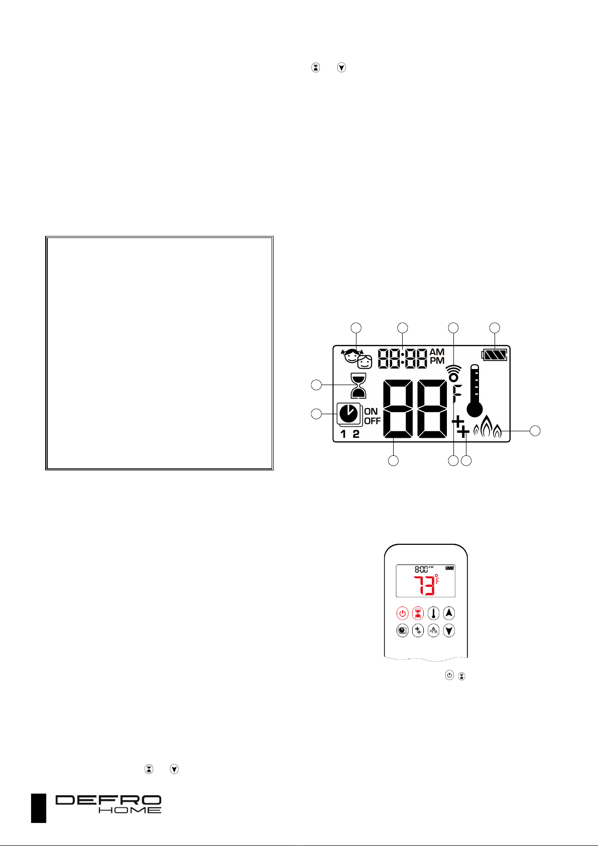
7.6. CONTROL OF FIREPLACE WITH A REMOTE CONTROL
DEFRO HOME VITAL heater is controlled via the 8-button remote
control. The picture presents the remote control screen with a
description of icons and s mbols.
Picture 23. Remote control display screen.
1 - parental lock 2 - time 3 - signal indicator 4 - battery condition 5 -
temperature 6 - timer 7 - programme mode 8 - economy mode 9 -
additional functions 10 - temperature unit.
7.6.1. SETTING TEMPERATURE UNITS
Press both buttons at the same time: . This will change the
temperature units from ⁰C to ⁰F or from ⁰F to ⁰C.
1
6
7
2 3 4
10 95
8
17
7.6.2. TIME SETTINGS
Press both buttons at the same time: .
Using or button select the number for the given da ,
e.g. 1 - Monda , 2 - Tuesda etc.).
Confirm the da b simultaneous pressing of two buttons as
in item 1. Hour field will start flashing.
Select current hour using buttons .
Confirm selected hour b simultaneous pressing of both
buttons. Minutes field will start flashing.
Set the current minute using buttons. Confirm settings with
simultaneous pressing of both buttons or wait for a while.
7.7. PARENTAL LOCK
In parental lock mode onl the switch off button is active.
Press both red buttons simultaneousl to activate the lock.
Lock icon will be displa ed .
The lock is switched off b simultaneous pressing of both
buttons: and .
7.7.1. FIRING UP IN MANUAL MODE
Before manual ignition of the chimne initiated from the remote
control, please make sure that:
MANUAL knob on GV60 valve is in ON position (full rotation
- counterclockwise).
If the ON/OFF switch is part of the equipment, it should be
set to I(ON) position.
Press and hold the button (firing with one button) on
remote control or two button and at the same time
(firing up with two buttons) until two short audible signals will
be heard and an icon confirming the ignition will be flashing
on the displa . Release the buttons.
The gas will flow to the primar burner after confirmation of
ignition.
Remote control automaticall switches to manual control
mode.
7.7.2. STANDBY MODE
The equipment goes to standb mode after pressing and holding
the button, what results in damping of the primar burner and
maintaining the flame onl in control burner.
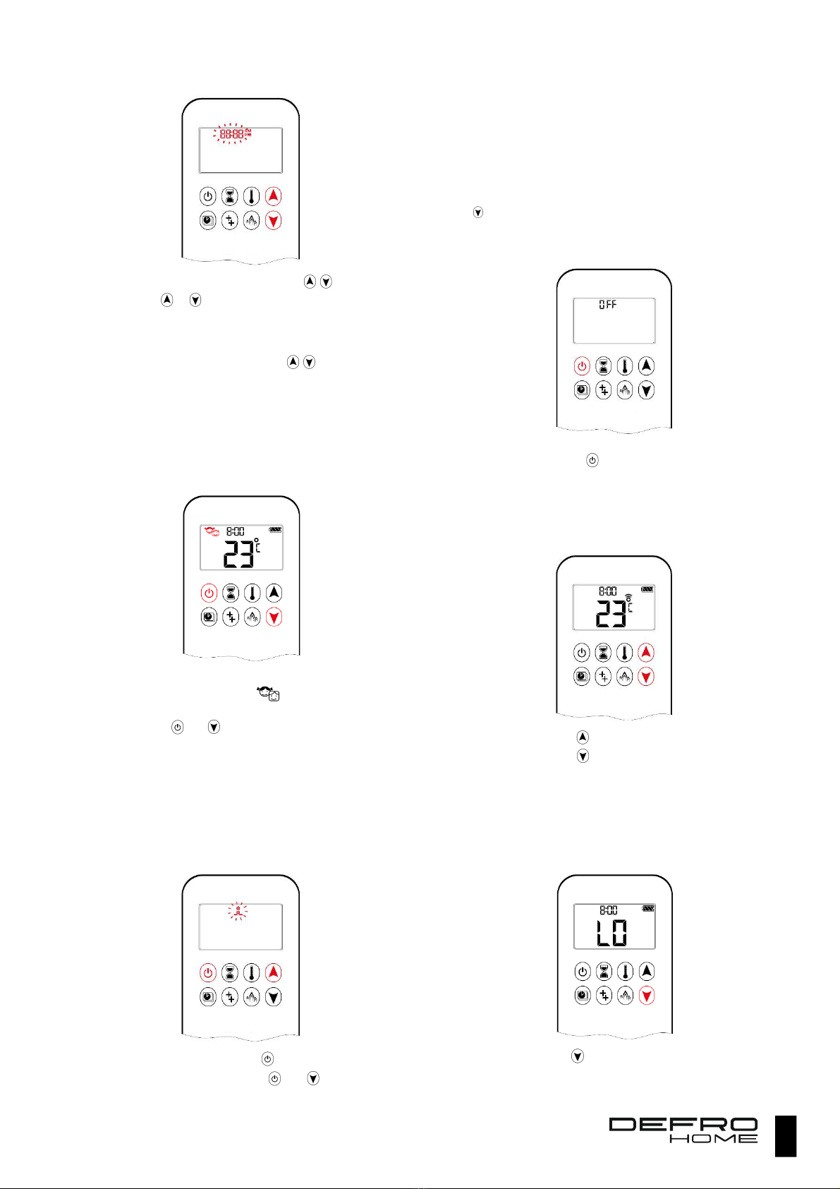
7.7.3. FIREPLACE SHUTDOWN
Press the button to switch off the heater, what will be
confirmed b displa ing the OFF text on the remote control
displa .
Attention! Next firing up is possible when OFF stops flashing.
7.7.4. ADJUSTMENT OF FLAME HEIGHT
Press and hold button to increase flame height.
Press and hold button to decrease flame height.
7.7.5. ADJUSTMENT OF LIMIT HEIGHTS FOR THE FLAME
Remote control allows setting maximum or minimum height of the
flame.
Attention! Switch to minimum flame is preceded by its
instantaneous increase.
Double click the button to decrease the flame to
minimum height. Confirmation of executed operation is LO
text displa ed on the screen.
18
Increase to maximum flame height takes place after double
click of button, what is confirmed with HI message.
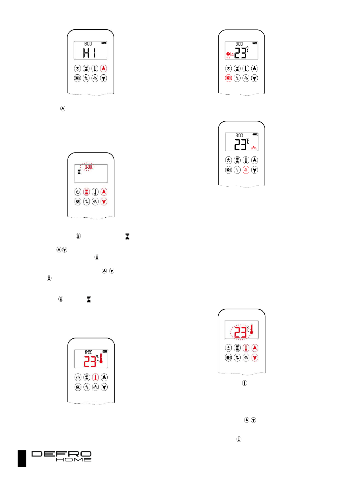
7.7.6. TIMER
Timer operates in Manual, Thermostatic and Eco(nom ) mode.
Flame in the fireplace is damped after the set time has elapsed.
Maximum countdown time until damping is 9 hours and 50
minutes.
Timer switch on
Press and hold the button until an icon will appear on
the screen, and the hour field of the counter start flashing.
Use buttons to set hours of fireplace operation.
Confirm the setting with button. Minute field will start
flashing.
Set additional minutes using buttons. Confirm with
button.
Timer switch off
Press button, icon and counter will disappear from the
remote control screen and counting will be cancelled.
7.7.7. OPERATING MODES
The heater ma operate in one of three modes (buttons activating
the given mode are red on the pictures):
Thermostatic mode is based on measurement of room
temperature where the heater is located and control of flame
height so as to maintain the temperature set in the controller.
Programmed mode is one of two programs set, which
specif when the heater should operate and what
temperature should be maintained.
Eco mode controls the fireplace so as to maintain the set
temperature, but in the more economical wa . The controller
forces maximum height of the flame if the temperature is too
low. If the temperature is too high, then the minimum flame
will be set. One c cle lasts approx. 20 minutes.
7.7.8. THERMOSTATIC MODE
In thermostatic mode, ambient temperature is compared with a
thermostat temperature and the fireplace power is modulated
correspondingl to the difference of both temperatures. Ambient
temperature is measured b a sensor installed in the remote control,
therefore it should not be subjected to additional heat e.g. b exposing
it to the direct sunlight. If the temperature of the remote control exceeds
the ambient temperature, then measuring errors will cause cold spots
in the room.
Attention!!!
Do not store the remote control near the fireplace or in a place
exposed to sunlight.
Switch the mode on with button. A thermometer icon will
be displa ed on the screen. Set temperature will be displa ed
next to this icon for a while and then room temperature will
be shown.
Press and hold the button with thermometer until
thermometer icon starts flashing.
Set the temperature using buttons.
Confirm the temperature using button with thermometer.
The mode is switched off after ou:
o Press the button.

19
o Press the buttons.
o Press the buttons causing switch to the other
modes or .
7.7.9. PROGRAM MODE
The program mode allows setting fireplace operating times for
each da of the week. The heater switches on during operation when
ambient temperature is lower than set switch on temperature and it
switches off after reaching the switch off temperature.
Switch on temperature is the same temperature, which has been
set in the thermostatic mode. So, onl switch off temperature and
operation times are configured after selection of the program mode.
Default values of temperatures:
Switch on temperature 21⁰C,
Switch off temperature: ”--” (onl control flame).
Switch on the mode using button, the following icons will
be shown on the displa :
Temperature configuration:
o Press and hold until the flashing icon will
be displa ed. ON message and switch on
temperature will be displa ed (temperature set in
thermostatic mode),
o To set the switch off temperature, ou should
press or wait a while . OFF message will be
displa ed and temperature will flash.
o Select required temperature with buttons.
o Confirm the with button.
Configuration of operation times:
o The ALL. message should flash on the displa
after confirmation of switch off temperature.
o Pressing selection ke s, ou can switch
between the da s of the week:
ALL – one setting for all da s
SA:SU – separate setting for
Saturda and Sunda
1, 2, 3, 4, 5, 6, 7 – separate settings
for each da of the week (Dail
Timer).
Confirm the selection with a ke . The s stem waits for
configuration of switch on time in the next step.
Mode ALL
Configuration of program switch on time no. 1:
Icon and s mbols 1, ON will be displa ed, message ALL
will be shown for a while and hours field will flash.
Select switch on hour using the buttons
Confirm the hour with . ALL will be displa ed once again
for a while and minutes field will be flashing.
Select minutes using buttons.
Confirm the setting once again with the button . The
s stem will go to configuration of switch off time.
Switch off time configuration:
o The displa will show, except the icon, 1, OFF,
message ALL and flashing hours field.
o Select the hour with the selection buttons.
o Confirm with button. ALL will be displa ed
once again for a while and minutes field will be
flashing.
o Set the minutes using buttons.
o Confirm with button. The s stem will go to
configuration of program no. 2 in the same wa as
for no. 1.
If ou want to avoid configuring program no. 2 - stop entering
the times and program no. 2 will remain inactive.
Mode SA:SU or Daily Timer
Switch on and switch off times are set in the same wa as in
ALL mode
For SA:SU mode ou set one switch on and switch off time
for both da s at the same time.
In Dail Timer mode the unique switch on and switch off times
can be set for one, selected da , several da s or for each da
of the week.
Notes!!!
Program no. 1 and no. 2 uses the same setting of switch on and
switch off temperature setting for each mode. Change of both
temperatures in thermostatic mode results in setting both these
values are new default values and they become switch on and
switch off temperatures for the programmed mode.
Configuration of the switch on and switch off times for the
Programs no. 1 and no. 2 causes that they will become new default
values. Restoring the factory settings for both programmes ta e
place after resetting the remote control by ta ing the batteries out.
7.7.10. ECO MODE
Press button to switch on Eco mode, an icon will be
shown on the displa .
Press button once again to switch off the Eco mode.
7.7.11. BEHAVIOR OF FIREPLACE WHEN THERE IS NO SIGNAL
FROM THE REMOTE CONTROL
The flame will be automaticall reduced to minimum level if there
is no command from remote control within six (6) hours. The control
s stem will shutdown the equipment and shut off the gas suppl if the
20
fireplace operates continuousl without supervision for five (5)
successive da s.
7.8. POWER SUPPLY AND BATTERY REPLACEMENT
If you hear the signal indicating that the batteries are
discharged, it is required to replace them or remove the
worn out pieces if you plan to decommission the heater
.
Do not leave discharged batteries in the remote control
or receiver because it may lead to destruction of both
devices if their contents flow out.
Do not use accumulators to supply the receiver!
Use only appropriate type of batteries for the receiver
and remote control
Batteries used to suppl remote control and s stem of the receiver
are discharged during operation. Both devices inform about discharge
of the batteries. The remote control is equipped with a batter condition
indication icon. The receiver indicates that batter level is low with three
(3) audio signals. If the user does not replace the batter before the
are completel discharged, then the receiver will cut off the gas suppl
to the fireplace.
The receiver can be connected to the power suppl unit operating
at 4.5V connected to the AC network. It is forbidden to use the batteries
if the power suppl unit is in operation. Remove them from the chamber
in the receiver!
7.8.1. BATTERY REPLACEMENT IN THE REMOTE CONTROL
Reverse the remote control and remove the cover.
Remove discharged batteries.
Insert AAA batteries acc. to the designation available in
batter compartment.
Install cover.
7.8.2. BATTERY REPLACEMENT IN THE RECEIVER
Remove cover from the receiver.
Remove discharged batteries.
Insert AA batteries into the recess acc. to the designations.
Install cover.
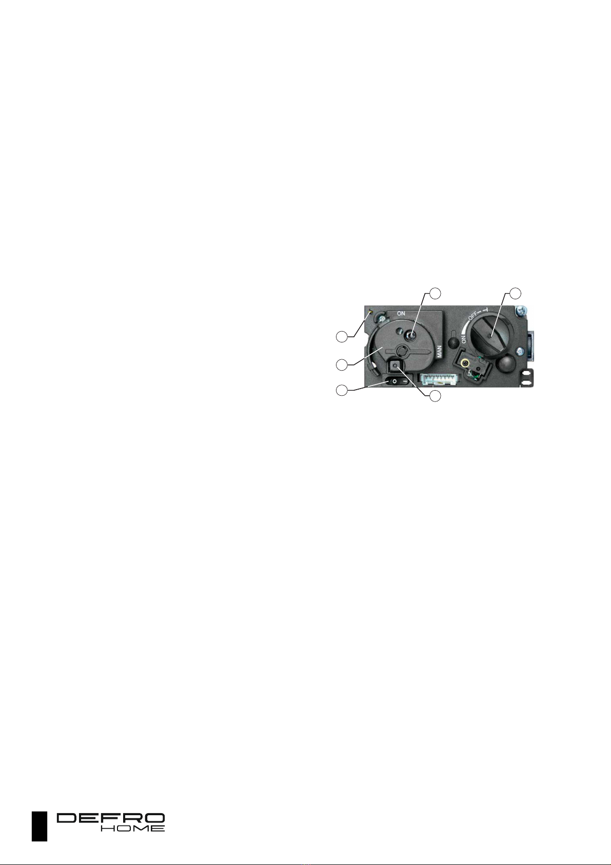
7.9. MANUAL CONTROL OF FIREPLACE
Gas-fired heater can be operated also without remote control in
manual control mode. All operations are then performed directl from
the GV60 valve level located inside the cabinet. Control components
used during manual control are presented on the picture 24.
To perform manual firing up of the fireplace ou should disconnect
cable of spark igniter from receiver module and connect it directl to
the GV60 valve, to contact of piezoelectric igniter (1 on picture 14).
7.9.1. FIRING UP
Open gas suppl valve.
If the ON/OFF switch is installed (3 on picture 24) then set it
to ON position (press s mbol I)
Turn the control knob of the main burner clockwise to the
max. position (4 on picture 24)
Set manual control knob to MAN (2 on picture 24).
This position uncovers a metal button (5 on picture 24) in the
bigger opening of the knob, which should be pressed and
held to suppl gas to the control burner.
Press several times square button of piezoelectric spark
igniter (6 on picture 24) while still pressing the metal button
until control burner ignites.
Press the metal button for another 10 seconds until control
flame appears.
If the control flame goes out before the next manual ignition
attempt, the process can be repeated after 5 minutes of wait.
Set control knob to ON (2 on picture 24). The primar burner
should ignite if the primar burner knob is not set to OFF.
Set flame size using the control knob of primar burner (4 on
picture 24)
Picture 24. Arrangement of controls required for manual control of
fireplace.
7.9.2. DAMPING A FLAME OF THE PRIMARY BURNER
Turn the control knob of primar burner (4 on picture 24) to
the right until a distinctive click will be heard. The primar
burner should go out and control burner should be burning
still.
7.9.3. FIREPLACE SHUTDOWN
Set ON/OFF switch (3 on picture 24) to OFF (O). Control
burner should go out.
If the heater is shutdown for a longer time, then it is required
to cut off air suppl using a valve located on the control
cabinet.
1
5
6
4
2
3
This manual suits for next models
1
Table of contents
Popular Heater manuals by other brands

BAIEKUR COILS
BAIEKUR COILS HOT COILS 400 user manual

Campo Equipment
Campo Equipment Blaze EB400G troubleshooting guide

Empire Heating Systems
Empire Heating Systems RH-25-8 Installation instructions and owner's manual

Truma
Truma S 3004 installation instructions

Aim
Aim AHH4 user manual

TriangleTube
TriangleTube Delta Elite F-25 instructions


