manuals.online logo
Brands
  1. Home
  2. •
  3. Brands
  4. •
  5. Campo Equipment
  6. •
  7. Heater
  8. •
  9. Campo Equipment Blaze EB400G User manual

Campo Equipment Blaze EB400G User manual

EB400G Field Assist Troubleshooting Guide
Burner control is locked-out on reset Burner control is NOT locked-out on reset
1
Page 15
Page 2
Welcome to the Campo “Field Assist Troubleshooting Guides”.
These guides were developed to assist the working technicians in the field. We’ve supplied issues
and solutions to the most common problems encountered in the field. If you need assistance while
troubleshooting on the job, they are easy to store in your smart phone, tablet or computer.
Getting Started is easy! Just click on ‘Page #’
for the problem you are encountering
➢Contact Us…Page 30
➢Tech Tips and Bulletins for you…Page 31 +
➢Quick set-up and Installation Guides and Tools of the Trade for you…Page 33 +
HOME
•Before resetting the burner control, ensure you have between 7-14” WC
pressure supplied to the gas valve.
•Ensure the ‘switchover valve’ is in the proper position for LP OR NG
Burner is locked out on reset
•You reset the control and it goes through the 60 second purge, but doesn’t
ignite…… Page 3
•You Reset the Burner Control. The Burner motor Does Not Start and the
Burner Control Locks-out on Reset…Page 10
•You Reset the Burner Control, but the reset light is solid red during the pre-
purge, and the control locks out on reset… Page 13
•You Reset the Burner Control and after the pre-purge, the burner fires up,
but the flame goes out after 5 to 10 seconds... PAGE 14
2
HOME
You reset the control and it goes through the 60 second
purge, but doesn’t ignite…
Outlet port
•Install your manometer in the outlet port of the gas valve.
•Reset the burner control.
•After the 60 second purge, check to see if gas pressure is
coming through the valve.
•Keep a close eye on the manometer, as the pressure will only
register for 1 or 2 seconds after the 60 second pre-purge.
NOTE: If gas pressure is present… Page 4
If gas pressure is NOT present… Page 6
3
HOME
If gas pressure is present…
➢Test the components... Page 5
✓Defective igniter
✓Defective ignition cable
✓Broken electrode
4
3.5
HOME
Testing the Igniter
5
1. Inspect the ignition electrode for cracks.
2. Inspect the ignition cable for cracks.
3. Inspect the electrode gap, ensuring the gap is 1/8”.
•With the gun still outside the burner casing, re-connect the
ignition cable to the igniter.
•Ensure the gas gun is WELL GROUNDED to the burner
housing when testing for spark.
•Reset the burner control and check for spark after the pre-
purge.
•Keep a close eye on the electrode as the spark will only
appear for 1 second AFTER the 60 second pre-purge.
Ignition Cable Electrode (Gap 1/8”)
✓No spark indicates a defective igniter
SHUT OFF the gas supply to the burner before testing!
HOME
If gas pressure is NOT present…
✓ON/OFF switch is in the OFF position
✓Defective 24v Transformer
✓Defective Burner Control
✓Defective gas valve
➢Test the components…Page 7
6
HOME
Checking the ON/OFF switch
➢Continue to… Page 8
7
•Ensure the ‘switchover valve’
is in the proper position for LP
OR NG
•Ensure the gas valve switch is
in the ON position.
HOME
Checking the 24 volt transformer
Check black and red stripe wires on 6 prong plug
For 24 volts
✓If 24 volts is NOT present, the transformer is
defective.
•If 24 volts is present… Page 9
8
HOME
Checking the burner control and gas valve
Reset the Burner Control. After the 60 second purge,
check for 24 volts on the white and violet wires on the 6
prong plug.
✓If 24 volts is present, after the 60 second purge, the gas
valve is defective.
✓If 24 volts is NOT present after the 60 second purge,
the burner control is defective.
9
HOME
You reset the burner control. The burner motor does not
start and the burner control locks out on reset.
✔Defective burner motor.
✔Defective Burner Control
✔Defective Motor Relay
➢Test the components…Page 11
10
Light Flashing reset control
HOME
Checking burner motor, motor relay and burner control
Reset burner control, then check for 120 volts on
burner motor relay coil.
✓If 120 volts is NOT present, defective
burner control
✓If 120 volts is present, defective burner
motor relay OR burner motor
➢Checking burner motor and motor relay…Page 12
11
HOME
Checking burner motor and motor relay (continued)
Reset the burner control and check for 120
volts going to the burner motor.
✓If 120 volts is present, defective
burner motor
✓If 120 volts is NOT present, defective
burner motor relay
12
HOME
You reset the burner control, but the reset light is solid red
during the purge, and the control locks out on reset
✓The air proving switch is defective
✓The air hose is cracked or busted
13
➢Note: The air proven switch contact must
be open to start and close after the
burner motor starts.
HOME
You reset the burner control and after the pre-purge, the
burner fires up, but the flame goes out after 5 or 10 seconds.
✔The flame rod is defective or dirty
✔Flame rod lead wire is defective
14
•Clean or replace flame rod and wire.
➢NOTE: do not use sandpaper to clean flame
rod. A cloth will be sufficient.
HOME
•If the Burner Control is NOT locked out on Reset and will not start… Page 16
•If the Circulating Fan Fails To start… Page 23
•If the fan is starting intermittently, erratically or inconsistently…Page 24
•Circulating Fan Does Not Shut Off… Page25
15
The Burner is NOT locked out on reset
HOME
If the Burner Control is NOT locked out on Reset
and will not start…
Check for 120 volts between Terminal (L1) and
Common (L2) on the burner control.
•If 120 volts is present… Page 17
•If 120 volts is NOT present…Page 19
L1 L2
16
HOME
✓Defective Bypass Switch
✓Defective Burner Control
If 120 volts is PRESENT on burner control…
➢Test the components... Page 18
Jump TR-TW
17
HOME
Testing the bypass switch and burner control
To check the bypass switch, place a jumper wire
on terminals TR-TW
✓If the burner starts, the bypass switch is defective
✓If the burner does not start, the burner control
is defective
Jump TR-TW
Terminals TR-TW
18
HOME
If 120 volts is NOT present on burner control between
L1 and (L2)
✓Defective Thermal Limit Disc 150⁰F
✓Defective Thermocouple
✓Defective Temperature Controller
✓Defective Fan Motor Thermostat Switch
19
➢Test the temperature controller… Page 20
Thermal Limit Disc
Temperature Controller Thermostat
Switch Inside Fan
Motor
Thermostat
Switch Sealed
Inside Fan Motor
Not serviceable
Thermocouple
HOME
Testing the temperature controller
20
Check for 120 volts on the orange wire terminal #6 on the
temperature controller.
✓If 120 volts is NOT present, the temperature controller
is defective.
✓If voltage is present, the 150F thermal limit disc is
defective or the thermal heat thermostat in the fan
motor is defective… Page 21
➢NOTE: If the display on the temperature controller is
reading 000 (or other false reading), the thermocouple
Is defective.
HOME

Other Campo Equipment Heater manuals

Campo Equipment BLAZE 1.5E User manual

Campo Equipment

Campo Equipment BLAZE 1.5E User manual

Campo Equipment BLAZE 150E User manual

Campo Equipment

Campo Equipment BLAZE 150E User manual

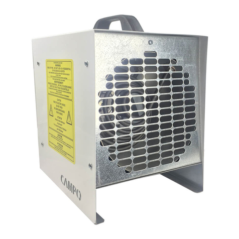
Campo Equipment ECOBlaze 200D Turbo User manual
Campo Equipment

Campo Equipment ECOBlaze 200D Turbo User manual

Campo Equipment BLAZE 9E User manual

Campo Equipment

Campo Equipment BLAZE 9E User manual

Campo Equipment ECOBlaze DF1600 User manual

Campo Equipment

Campo Equipment ECOBlaze DF1600 User manual

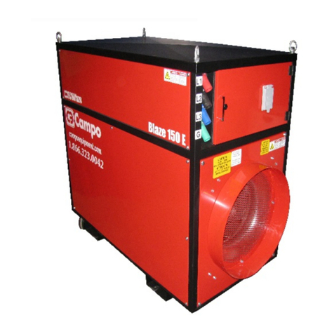
Campo Equipment ECOBlaze DF2500 User manual
Campo Equipment

Campo Equipment ECOBlaze DF2500 User manual

Popular Heater manuals by other brands

Porter-Cable PCXH80KT Operating instructions and owner's manual

Porter-Cable

Porter-Cable PCXH80KT Operating instructions and owner's manual

Dyna-Glo RA18LPDG user manual

Dyna-Glo

Dyna-Glo RA18LPDG user manual

Dimplex PLX050E instruction manual

Dimplex

Dimplex PLX050E instruction manual

EOS Herkules XL S120 installation instructions

EOS

EOS Herkules XL S120 installation instructions

Trebs Comfortheat 99209 manual

Trebs

Trebs Comfortheat 99209 manual

Biddle STYLE2 Series Installation operation & maintenance

Biddle

Biddle STYLE2 Series Installation operation & maintenance

Vermont Castings Non-Catalytic Convection Heater 2477CE Installation and operating manual

Vermont Castings

Vermont Castings Non-Catalytic Convection Heater 2477CE Installation and operating manual

Fagor RA-1505 Instructions for use

Fagor

Fagor RA-1505 Instructions for use

THERMAL FLOW Delta 175 Operating instructions manual

THERMAL FLOW

THERMAL FLOW Delta 175 Operating instructions manual

GET G2CH instructions

GET

GET G2CH instructions

ApenGroup PK Series User, installation, and maintenance manual

ApenGroup

ApenGroup PK Series User, installation, and maintenance manual

oventrop Regucor Series quick start guide

oventrop

oventrop Regucor Series quick start guide

Blaze King CLARITY CL2118.IPI.1 Operation & installation manual

Blaze King

Blaze King CLARITY CL2118.IPI.1 Operation & installation manual

ELMEKO ML 150 Installation and operating manual

ELMEKO

ELMEKO ML 150 Installation and operating manual

BN Thermic 830T instructions

BN Thermic

BN Thermic 830T instructions

KING K Series Installation, operation & maintenance instructions

KING

KING K Series Installation, operation & maintenance instructions

Empire Comfort Systems RH-50-5 Installation instructions and owner's manual

Empire Comfort Systems

Empire Comfort Systems RH-50-5 Installation instructions and owner's manual

Well Straler RC-16B user guide

Well Straler

Well Straler RC-16B user guide

manuals.online logo
manuals.online logoBrands
  • About & Mission
  • Contact us
  • Privacy Policy
  • Terms and Conditions

Copyright 2025 Manuals.Online. All Rights Reserved.