Degre K LOLe 1 User manual

4, rue de Jarente - F 75004 Paris
Tel: +33 (0)1 71 18 18 60
Fax : +33 (0)9 70 80 10 00
A a u c a p i t a l d e 1 0 5 0 0 0 € R C P a r i s B 4 0 2 2 1 1 0 1 5
T V A : F R 0 5 4 0 2 2 1 1 0 1 5
1/29
LOLe 1 Installation manual
Version December 2009
Table of contents
I- INTRODUCTION……………………………………………………………………………….……………p.3
II- CEILING VERSION: LOLe 1.P…………………………………………………………….…………….p.4
1. Installation of the ceiling adapter and ceiling arm…………………….……….…………….p.4
1.1 Assembling the ceiling adapter and attaching to the arm…............……….………….p.5
1.2 Attaching the ceiling adapter to a concrete ceiling ………………………………...…...p.8
1.3 Attaching the ceiling adapter to a wooden ceiling……………………………….…..….p.10
2. Connection of the power supply cables…………..………………………………..……..…..p.10
3. Attaching the light arm to the ceiling arm..........…………………………………………..….p.12
4. Attaching the light head to the light arm.……………………………………………………...p.14
III- DENTAL UNIT ADAPTATION VERSION : LOLe 1.E………………….………………………….….p.15
1. Remove the existing light………………..……………………………………………………..…p.16
2. Arm installation…………………………..………….……..………….……………………………p.18
3. Attaching the light head to the light arm…………………………….…………………………p.18
4. Connection of the power supply cables………………………………………………………..p.19
IV- WALL VERSION: LOLe 1.M……………………….………………………….…………………………p.20
1. Installation of the wall adapter plate…………………………………………………………….p.21
2. Connection of the power supply cables ……………………………………………………....p.22
V- ADJUSTMENTS………………………………………………………………………………………...….p.24
1. Adjustment of the friction of the arm lifting joint…….…………………………………….…p.24
2. Adjustment of the friction of the head lifting joint……………………………………………p.24
3. Adjustment of the rotational friction of the head joint……………….……………………...p.26

4, rue de Jarente - F 75004 Paris
Tel: +33 (0)1 71 18 18 60
Fax : +33 (0)9 70 80 10 00
A a u c a p i t a l d e 1 0 5 0 0 0 € R C P a r i s B 4 0 2 2 1 1 0 1 5
T V A : F R 0 5 4 0 2 2 1 1 0 1 5
2/29
4. Adjustment of the rotational friction of the arm joint……………………………..………….p.26
VI- LED ASSEMBLY: Opteled………………………………………………….……………………………p.27
. 1. Replacement of an opteled …………………………………………......……….…….……….p.27
2. Adjusting position of all opteleds………………….............…………………………………...p.29
. 3. Check of the opteled circuit good working……...........…………………………………...……p.30
The manufacturer, assembler and importer are responsible for the safety,
reliability and performance of the unit only if:
- installation, calibration, modification and repairs are carried out by qualified
and authorized personnel
- electrical installations are carried out according to the appropriate
requirements such as IEC364
- equipment is used according to the operating instructions
The manufacturer pursues a policy of continual product development. Although
every effort is made to produce up-to-date product documentation, this
publication should not be regarded as an infallible guide to current specifications.
We reserve the right to make changes without prior notice.
© 2008-01

4, rue de Jarente - F 75004 Paris
Tel: +33 (0)1 71 18 18 60
Fax : +33 (0)9 70 80 10 00
A a u c a p i t a l d e 1 0 5 0 0 0 € R C P a r i s B 4 0 2 2 1 1 0 1 5
T V A : F R 0 5 4 0 2 2 1 1 0 1 5
3/29
I- INTRODUCTION
This manual explains how to install the LOLe operating light, to the ceiling using a ceiling adapter, to the wall with the
wall adapter plate or to the dental unit.
Please read those instructions carefully before installing the unit.
NOTE :
Information given in this manual should be taken as a general guide for proper installation of the LOLe
operating light. However, in case of contradiction to any local or national building regulations, the
building regulation must always override this manual. In this case, please contact previously to any
changes your local dealer.
NOTE :
The operating light must be serviced by qualified personnel only, trained by approved dealers. Repairs
and parts replaced by unqualified personnel carry no warranty.
ENVIRONMENTAL REQUIREMENTS
Strength requirement of the wall and ceiling:
The ceiling construction must be able to resist a withdrawal force of 70kg (154 pounds) at each of the three
attachment locations. Otherwise, some additional mounting supports must be used to fulfil this requirement.
The wall construction must be able to resist a shear load of 25kg (55 pounds) and a withdrawal force of 52kg
(115pounds) at each of the four attachment locations. Otherwise, some additional mounting supports must be
used to fulfil this requirement.
Temperature and humidity:
The operating temperature range is from +15°C to +3 5°C. The acceptable humidity range is from 15% to 85%.
The storage and transportation temperature range is from -5°C to +60°C.
4, rue de Jarente - F 75004 Paris
Tel: +33 (0)1 71 18 18 60
Fax : +33 (0)9 70 80 10 00
A a u c a p i t a l d e 1 0 5 0 0 0 € R C P a r i s B 4 0 2 2 1 1 0 1 5
T V A : F R 0 5 4 0 2 2 1 1 0 1 5
4/29
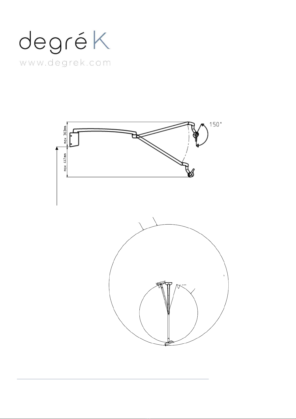
II- CEILING VERSION : LOLe 1.P
1.Installation of ceiling adapter and ceiling arm.
Warning : Ensure that the power supply is switched off before starting installation.
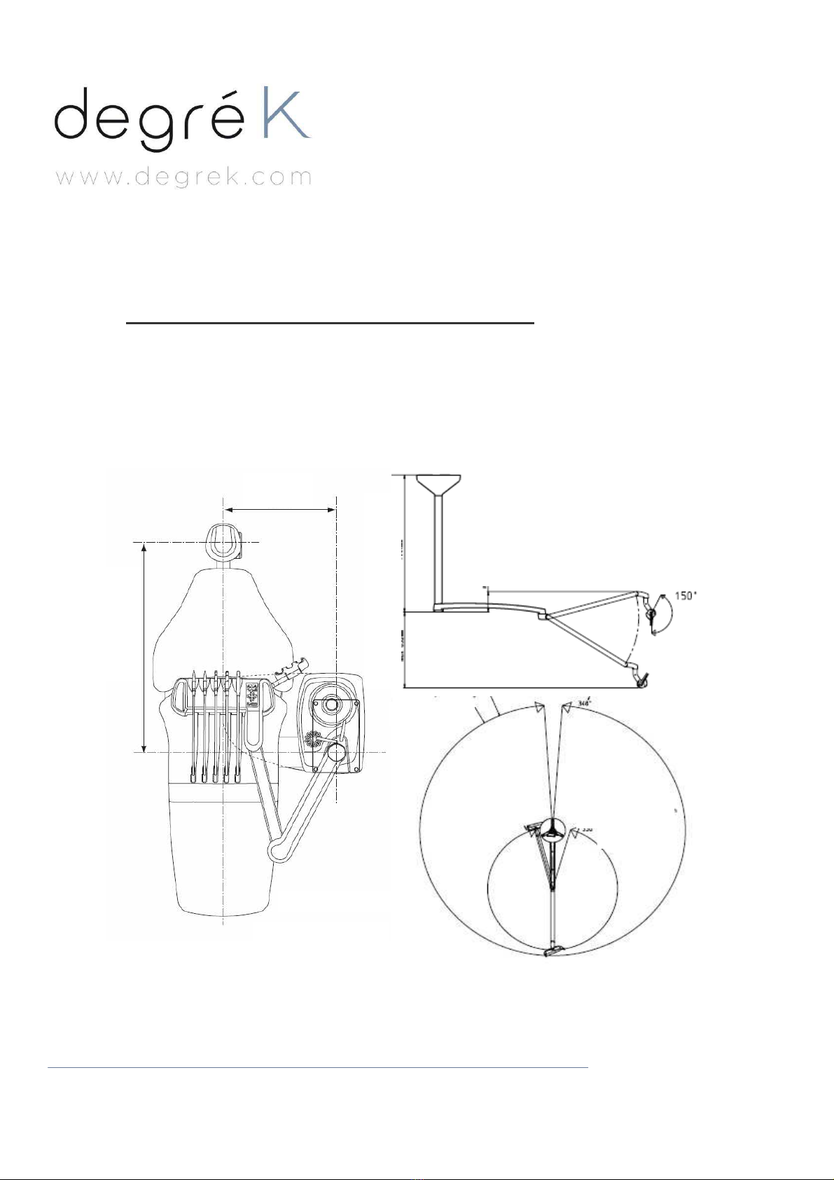
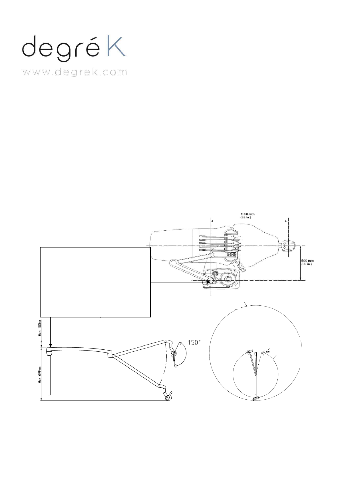
The central point of fixation has to be 1000mm far from the patient’s mouth and 500mm far from the unit axis, like on
the picture bellow.
For a Planmeca dental unit, this point is located on the same vertical as would be the own equipment’s light post.
1000mm
500mm
Max 632mm 1144mm
Max room height =3000mm
Max 172mm
R=1860mm
R=880mm
Foot
print
Side view
Top view
4, rue de Jarente - F 75004 Paris
Tel: +33 (0)1 71 18 18 60
Fax : +33 (0)9 70 80 10 00
A a u c a p i t a l d e 1 0 5 0 0 0 € R C P a r i s B 4 0 2 2 1 1 0 1 5
T V A : F R 0 5 4 0 2 2 1 1 0 1 5
5/29
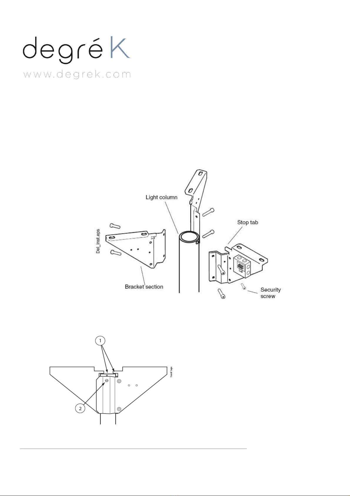
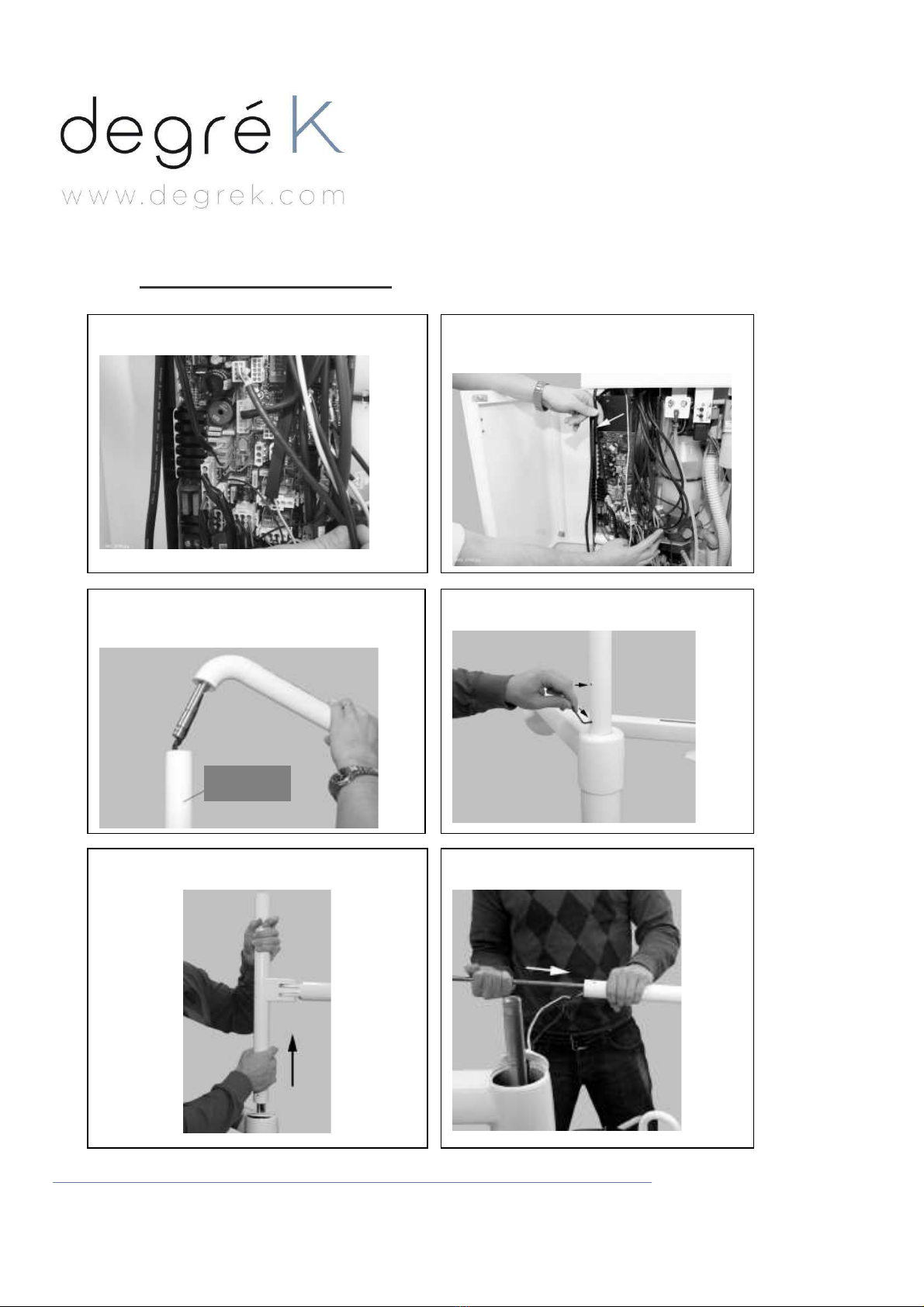
1.1 Assembling the ceiling adapter and attaching to the arm.
Shorten the ceiling arm if necessary. The provided arm can be used in 3m (118in.) high rooms. If the room is lower,
shorten the arm accordingly.
(Example: shorten the arm 500mm (20in.) if the room height is 2.5m.)
Use one of the bracket sections as a template and mark the position of the security screw hole that must be drilled with
a 5mm drill at the end of the light column. Note that the bracket must be positioned so that the small stop tab touches
the top of the light column (1).
Drill the holes for the security screw where it is marked on the light post (5mm Ø). Assemble the three parts of the
bracket and clamp them to the end of the column. Make sure that the security screw hole in the bracket sector lines up
with the hole that you have just drilled in the light column. Screw the security screw into the hole on the bracket section
and into the light column to secure it in its position (2)
4, rue de Jarente - F 75004 Paris
Tel: +33 (0)1 71 18 18 60
Fax : +33 (0)9 70 80 10 00
A a u c a p i t a l d e 1 0 5 0 0 0 € R C P a r i s B 4 0 2 2 1 1 0 1 5
T V A : F R 0 5 4 0 2 2 1 1 0 1 5
6/29
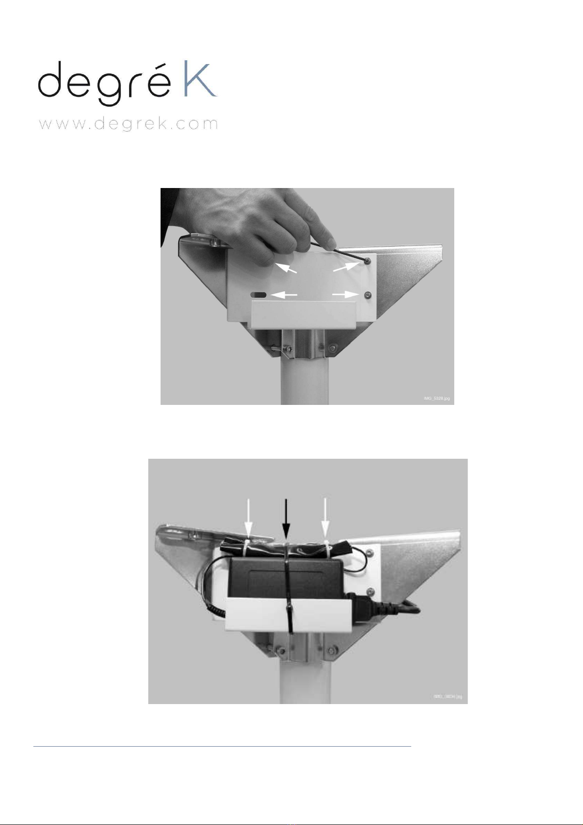
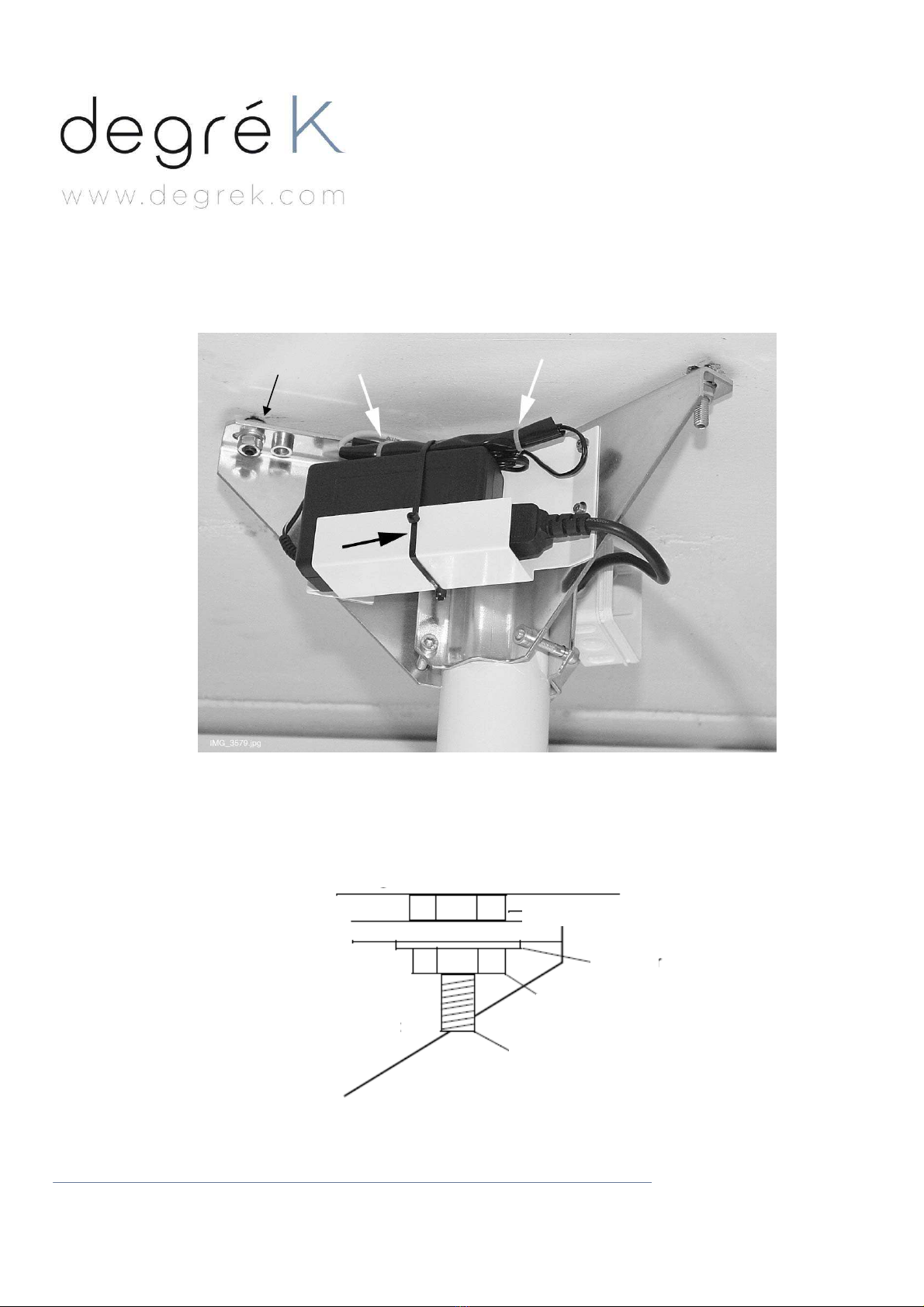
Attach the power supply support to the ceiling bracket with the four attachment screws provided.
Place the power supply to the support plate. Route the light cable through the ceiling arm. Slide the insulator onto the
cable. Connect the cable to the power supply cable and slide the insulator over the connectors. Secure the insulator
with cable ties (white arrows). Secure the power supply and cable connection to the support with cable tie (black arrow).
4, rue de Jarente - F 75004 Paris
Tel: +33 (0)1 71 18 18 60
Fax : +33 (0)9 70 80 10 00
A a u c a p i t a l d e 1 0 5 0 0 0 € R C P a r i s B 4 0 2 2 1 1 0 1 5
T V A : F R 0 5 4 0 2 2 1 1 0 1 5
7/29
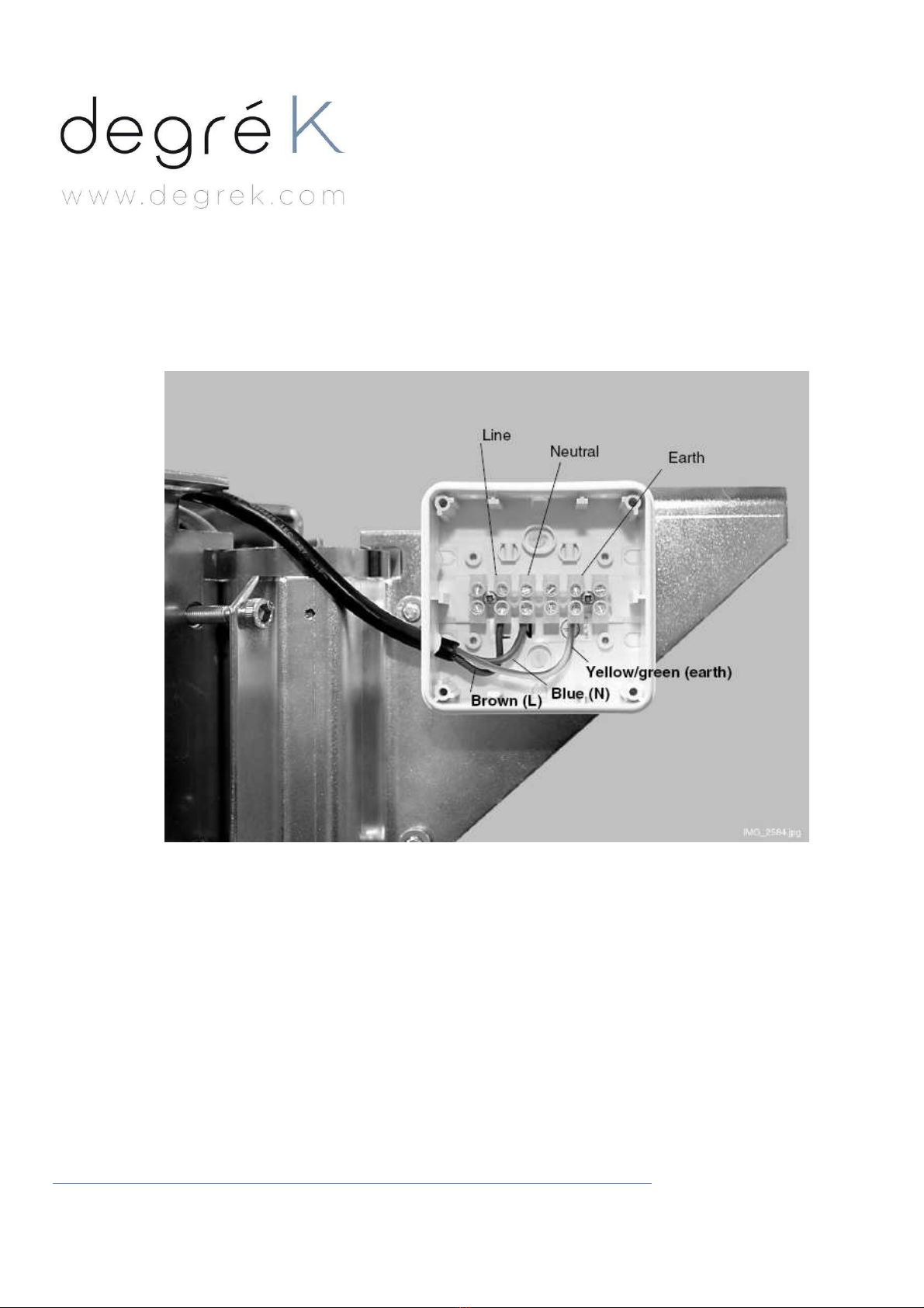
Attach the terminal block to the connection box and attach the connection box to one of the brackets with plastic
screws. Route the power supply cable into the connection box and connect the wires to the terminal block as shown in
the picture below.
Check the wire connections before operating the light. Wrong connection may be hazardous.
4, rue de Jarente - F 75004 Paris
Tel: +33 (0)1 71 18 18 60
Fax : +33 (0)9 70 80 10 00
A a u c a p i t a l d e 1 0 5 0 0 0 € R C P a r i s B 4 0 2 2 1 1 0 1 5
T V A : F R 0 5 4 0 2 2 1 1 0 1 5
8/29
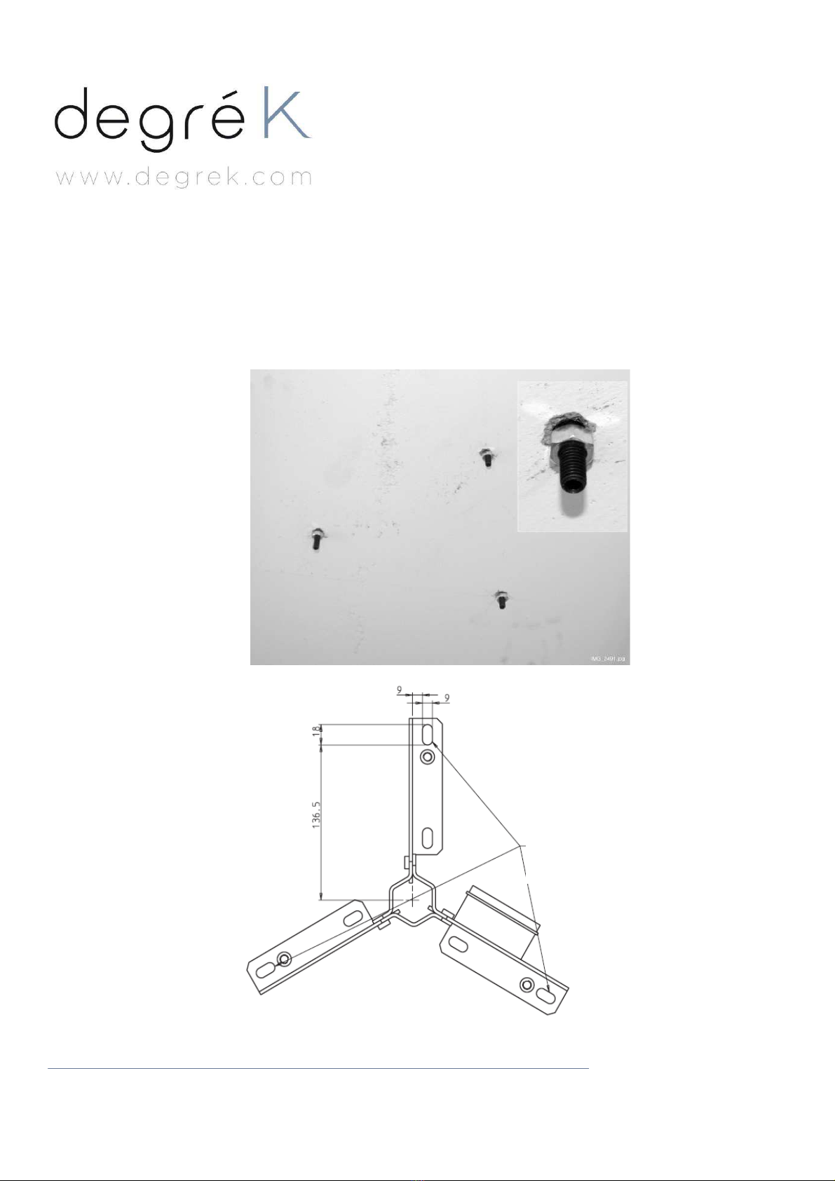
1.2 Attaching the ceiling adapter to a concrete ceiling
Use the assembled bracket and column as a template to mark the positions of the three bracket securing holes on the
ceiling.
Drill the holes Ø 10mm (3/8’’) and 30mm (13/16’’) deep. Insert the MK8 expansion screws in each hole and tighten
them in place.
Screw the levelling nuts on to the expansion screws.
Fastening
holes
4, rue de Jarente - F 75004 Paris
Tel: +33 (0)1 71 18 18 60
Fax : +33 (0)9 70 80 10 00
A a u c a p i t a l d e 1 0 5 0 0 0 € R C P a r i s B 4 0 2 2 1 1 0 1 5
T V A : F R 0 5 4 0 2 2 1 1 0 1 5
9/29
Make sure that the transformer and insulator are attached firmly to the support.
Lift the light arm into position on the expansion screws. Secure then the arm in place with the washers and securing
nuts.
Check the verticality of the arm, following 2 perpendicular axes (front/back and left/right). If necessary, loosen the
securing nuts and adjust the position by turning the appropriate levelling nut. After, tighten carefully the attachment
screws.
Washer and
securing nut
Ceiling
Washer
Bracket
Levelling nut
Securing nut
Expansion screw
M8x40 DIN 916

4, rue de Jarente - F 75004 Paris
Tel: +33 (0)1 71 18 18 60
Fax : +33 (0)9 70 80 10 00
A a u c a p i t a l d e 1 0 5 0 0 0 € R C P a r i s B 4 0 2 2 1 1 0 1 5
T V A : F R 0 5 4 0 2 2 1 1 0 1 5
10/29
1.3 Attaching the ceiling adapter to a wooden ceiling
Use the adjustment gutters provided. Place them (3x) on to the bracket sections. Lift the assembly arm/brackets into
position and attach it to the ceiling with 3x M8x50 DIN 571 screws.
Use M8x40 DIN 916 screws to adjust the horizontality of the assembly. The arm has to be vertical according to either
front/back or left/right axis.
2. Connection of the power supply cables.
The light must be hard wired to the mains (not plug connected). Every connection not enough fixed is able to disturb the
normal operating of the light. Route the wires into the connector box and attach them to their place properly, according
to the local installation requirements.
An external 2-poles mains switch that fulfils the local installation requirements must be provided by installator.
See principle diagram here bellow:
External 2-poles
Mains switch
Min : 2A/250V
Earth
Neutral
Phase
Input mains
4, rue de Jarente - F 75004 Paris
Tel: +33 (0)1 71 18 18 60
Fax : +33 (0)9 70 80 10 00
A a u c a p i t a l d e 1 0 5 0 0 0 € R C P a r i s B 4 0 2 2 1 1 0 1 5
T V A : F R 0 5 4 0 2 2 1 1 0 1 5
11/29
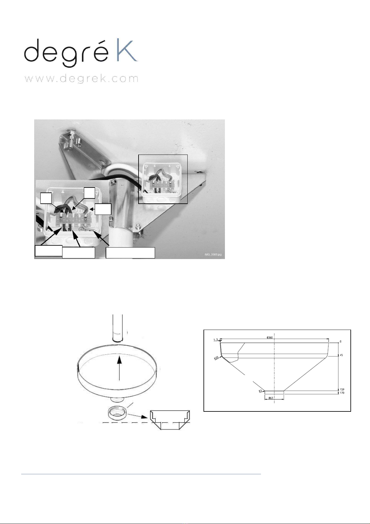
Connect the wires to the terminal block in the ceiling adapter as shown on the picture bellow:
Check the wire connections before switching on the operating light. Wrong connection may be hazardous.
Attach the connection box cover.
Slide the bracket cover and then the holding ring on to the ceiling arm. Note that the center part of the holding ring has
to be removed.
Brown
Blue
Yellow/green
Ceiling arm
Cover
Holding ring
Remove this section
A
Detailed A
L
N
PE
Dimensions
cacheplatine
Cover
dimensions

4, rue de Jarente - F 75004 Paris
Tel: +33 (0)1 71 18 18 60
Fax : +33 (0)9 70 80 10 00
A a u c a p i t a l d e 1 0 5 0 0 0 € R C P a r i s B 4 0 2 2 1 1 0 1 5
T V A : F R 0 5 4 0 2 2 1 1 0 1 5
12/29
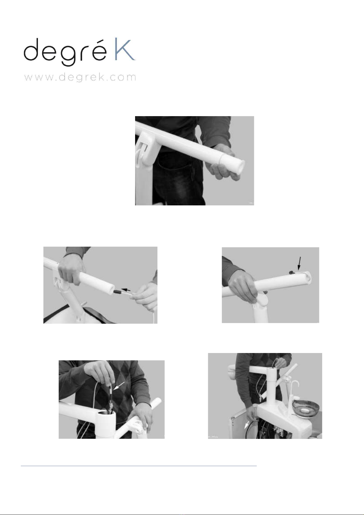
3. Attaching the light arm to the ceiling arm.
Warning : make sure that the mains power supply is switched off.
Bring the light arm near the bottom end of
the ceiling arm. Slide the insulator onto the
ceiling arm cable. Connect the light arm
cable connector to the connector from the
ceiling arm and slide the insulator over the
connectors.
Secure the insulator with cable ties.
Push the shaft of the light arm to the
ceiling arm. Attach the light arm with two
attachment screws especially
After tightening the attachment screws
fully, loosen them1/4 turns. Otherwise, the
joint rotational friction won’t operate
correctly because too large.

4, rue de Jarente - F 75004 Paris
Tel: +33 (0)1 71 18 18 60
Fax : +33 (0)9 70 80 10 00
A a u c a p i t a l d e 1 0 5 0 0 0 € R C P a r i s B 4 0 2 2 1 1 0 1 5
T V A : F R 0 5 4 0 2 2 1 1 0 1 5
13/29
Carefully push the excess cable out from the upper end of the ceiling arm. Place the cable below the cable tie that
attaches the power supply to its support plate. Push the cover up over the fixing brackets and secure it in place with the
holding ring.
Add the joint cover.
4, rue de Jarente - F 75004 Paris
Tel: +33 (0)1 71 18 18 60
Fax : +33 (0)9 70 80 10 00
A a u c a p i t a l d e 1 0 5 0 0 0 € R C P a r i s B 4 0 2 2 1 1 0 1 5
T V A : F R 0 5 4 0 2 2 1 1 0 1 5
14/29
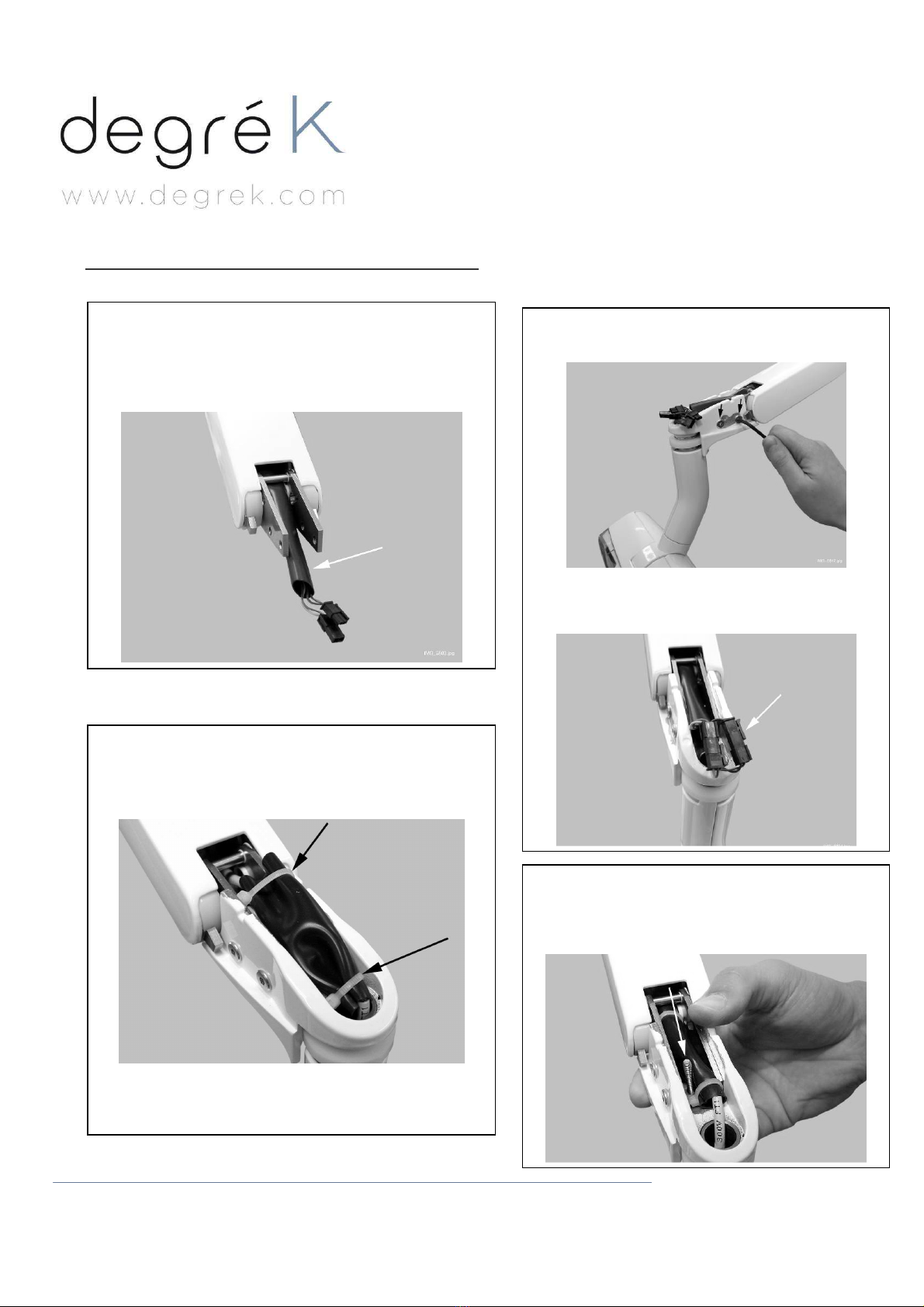
Attaching the light head to the light arm
1. At the factory, the arm cable is attached to the arm
with a cable tie.
Remove the cable tie before connecting the light
assembly.
4. Slide the insulator over the connectors. Secure with
cable ties.
2. Attach the light assembly to the LOLé arm with
four screws using the 3 mm Allen key.
3. Connect the arm cable connectors to the
connectors from the LOLé head.
5. Carefully attach the joint cover with one
attachment screw from below the joint using the
2.5 mm Allen key. Place the attachment screw first
to its position and then attach the cover.
4, rue de Jarente - F 75004 Paris
Tel: +33 (0)1 71 18 18 60
Fax : +33 (0)9 70 80 10 00
A a u c a p i t a l d e 1 0 5 0 0 0 € R C P a r i s B 4 0 2 2 1 1 0 1 5
T V A : F R 0 5 4 0 2 2 1 1 0 1 5
15/29
III- DENTAL UNIT VERSION : LOLe 1.E
NOTE :
Place the power supply outside patient area (more than 2m (79in) from dental unit).
It must not be placed on the floor.
Use the extension cable supplied with the operating light if needed.
NOTE :
Never splash water on the power supply.
NOTE :
Care must be taken when attaching the operating light to avoid damaging sensitive parts.
R=1860mm
R=880mm
Foot prin
t
Coupe
Top view
Point where the top of the light post must
be.
From patient’s head: 1000mm towards
feet and 500mm on the side (to be
adapted as the dentist is left-handed or
right-handed).
Caution, if the light post position isn’t like
on the picture, the scale of arms might
represent an interaction with the patient’s
head or the dentist’s assistant.
Warning :
!! In both position « patient arriving»
and sit position, the top of the light
post has to be at least at 1860mm
from the floor.
Side view
4, rue de Jarente - F 75004 Paris
Tel: +33 (0)1 71 18 18 60
Fax : +33 (0)9 70 80 10 00
A a u c a p i t a l d e 1 0 5 0 0 0 € R C P a r i s B 4 0 2 2 1 1 0 1 5
T V A : F R 0 5 4 0 2 2 1 1 0 1 5
16/29
1. Remove the existing light
1
-
Open the cuspidor door.
2
-
Disconnect the existing light power
supply cables.
3- Lift existing light away from the vertical
arm.
Bras
vertical
Verticalarm
4- Unscrew the existing column.
5- Lift the arm away from dental unit.
6- Remove the adapter in place.
4, rue de Jarente - F 75004 Paris
Tel: +33 (0)1 71 18 18 60
Fax : +33 (0)9 70 80 10 00
A a u c a p i t a l d e 1 0 5 0 0 0 € R C P a r i s B 4 0 2 2 1 1 0 1 5
T V A : F R 0 5 4 0 2 2 1 1 0 1 5
17/29
8- Route the new power supply cable
through the arm.
7- Insert the right adapter.
9- Prevent the cable from sliding into the vertical arm by
fastening it with tape.
10- Join the old and new cables together with
tape.
11- Route the new cable by pulling on the old one.
4, rue de Jarente - F 75004 Paris
Tel: +33 (0)1 71 18 18 60
Fax : +33 (0)9 70 80 10 00
A a u c a p i t a l d e 1 0 5 0 0 0 € R C P a r i s B 4 0 2 2 1 1 0 1 5
T V A : F R 0 5 4 0 2 2 1 1 0 1 5
18/29
2. Arm installation
Slide the insulator onto the arm cable. Connect the cable from the operating light to the cable coming from the arm.
Slide the insulator over the connectors and secure it with cable ties.
Mount the operating light to the light arm by pushing it into position.
3. Attaching the light head to the light arm
Assemble the light head to the arm following instructions given at §: II- 4. p.14
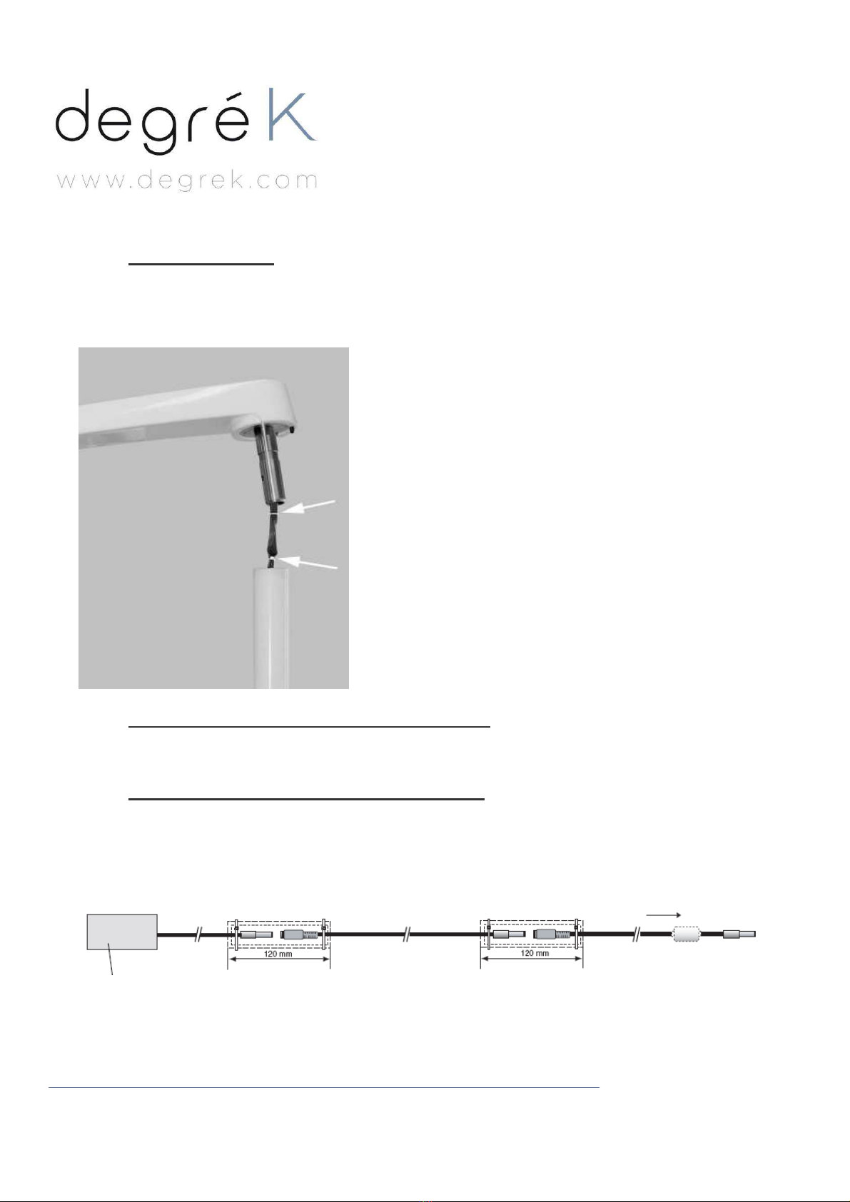
4. Connection of the power supply cables
Route the power cable out from inside the cuspidor.
If needed, connect the power extension cable to the power cable.
Connect the power extension cable to the power supply and isolate the connectors (double isolation)
Power supply double isolation double isolation to operating light
Power supply delivered with the operating light.
NOTE: Do not use any other power supply type with the operating light.
Connect the power supply to the mains outlet.
4, rue de Jarente - F 75004 Paris
Tel: +33 (0)1 71 18 18 60
Fax : +33 (0)9 70 80 10 00
A a u c a p i t a l d e 1 0 5 0 0 0 € R C P a r i s B 4 0 2 2 1 1 0 1 5
T V A : F R 0 5 4 0 2 2 1 1 0 1 5
19/29
IV- WALL VERSION: LOLe 1.M
Recommended maximum height from the floor: 1670mm
R=1950mm
R=880mm
4, rue de Jarente - F 75004 Paris
Tel: +33 (0)1 71 18 18 60
Fax : +33 (0)9 70 80 10 00
A a u c a p i t a l d e 1 0 5 0 0 0 € R C P a r i s B 4 0 2 2 1 1 0 1 5
T V A : F R 0 5 4 0 2 2 1 1 0 1 5
20/29
NOTE :
The light connections must be hard wired to the mains (not plug connected).
The wall adapter plate must be positioned so that the mains cable can be lead out (12cm) from the opening of
the adapter plate.
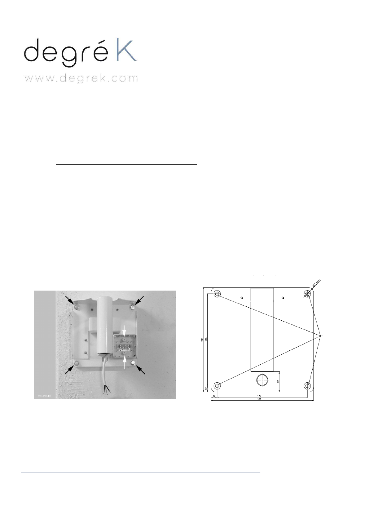
1. Installation of the wall adapter plate
Use the wall adapter plate as a template and mark the position of the four attachment screw holes.
- If the wall is made of concrete or brick, use the M8x30 DIN 912 screws and the expansion anchors.
Drill 4 Ø 10mm (0.4in.) and 32 to 35mm (1.25in.) depth holes, and place the expansion anchors into them.
Screw the plate to the wall.
- If the wall is made of wood or plaster, use the M8x50 DIN 571 lag screws.
Do not use the expansion anchors with wooden and plaster wall.
Drill 4 Ø 5mm, 25 to 30 mm in depth holes for the attachment screws.
Screw the plate to the wall.
Attach the connection box to the adapter plate with 2 plastic screws and nuts.
Trous de
fixation
Schéma platine
murale
Openings for
fastening
screws
Wall plate
Table of contents
Popular Medical Equipment manuals by other brands

Drive
Drive 15300 Owner's assembly and operating manual

Boston Life Labs
Boston Life Labs PC-68A user manual

Dr. Honle
Dr. Honle dermalight 80 operating instructions

Weinmann
Weinmann LIFE-BASE light XS Instructions for use

bort medical
bort medical 104 800 quick guide

Vatech
Vatech EzRay Air VEX-P300 user manual


