Netech MicroSim COS User manual


2
Warranty
Netech warrants the MicroSim COS against defects in
materials and workmanship for one year from the date of
original purchase. The standard warranty is extended for a
second year if the instrument is returned to Netech for its
recommended yearly recalibration.
During the warranty period, we will repair or, at our option,
replace at no charge a product that proves to be defective,
provided you return the product shipping prepaid to
Netech Corporation.
This warranty does not apply if the product has been
damaged by accident or misuse or as the result of service
or modification by other than Netech Corporation, or if its
serial number is defaced or removed.
Netech reserves the right to discontinue the MICROSIM
COS at any time, and change its specifications, price, or
design without notice and without incurring any obligation.
Netech guarantees violability of service parts for 5 years
after the manufacture of the unit is discontinued.
The warranty is void if you elect to have the unit serviced
and / or calibrated by someone other than Netech.
The warranty covering your product becomes void when
the tamper-resistant Quality Seal is removed or broken
without proper factory authorization.
We strongly recommend, therefore, that you send your
instrument to Netech Corporation for factory service and
calibration, especially during the original warranty period.
The purchaser assumes all liability for any damages or
bodily injury, which may result from the use or misuse of
the unit by the purchaser, his employees, agents, or
customers.
In no event shall Netech Corporation be liable for
consequential damages

3
General Information
Trademarks
MicroSim is the trademark of Netech Corporation. Any other trademark
names used in this manual are only for editorial purposes and the benefit
of the respective trademark owner with no intention of improperly using
that trademark.
Copyright
Copyright © 2007 by Netech Corporation. All rights reserved. No part of
this publication may be reproduced or transmitted in any form other than
for the purchaser’s personal use without written permission from Netech
Corporation.
Quality Assurance
Netech is ISO 9001-2000 Certified. This instrument was thoroughly tested
and inspected according to Netech’s ISO 9001-2000 quality standards
and test procedures and found to meet those specifications when it was
shipped from the factory.
Refunds and Credits
Please note that only serialized products and their accessory items (i.e.,
products and items bearing a distinct serial number tag) are eligible for
partial refund and/or credit. Non-serialized parts and accessory items
(e.g., cables, carrying cases, auxiliary modules, etc.) are not eligible for
return or refund. Only products returned within 90 days from the date of
original purchase are eligible for refund/credit.
In order to receive a partial refund/credit of a product purchase price on a
serialized product, the product must not have been damaged by the customer
or by the carrier chosen by the customer to return the goods, and the product
must be returned complete (meaning with all manuals, cables, accessories,
etc.) and in “as new” and resalable condition.
Products not returned within 90 days of purchase, or products, which are not in
“as new”, and resalable condition, are not eligible for credit return and will be
returned to the customer. The Return Procedure (see below) must be followed
to assure prompt refund / credit.
Restocking Charges
Products returned within 30 days of original purchase are subject to a
minimum restocking fee of 15 %, in excess of 30 days, 20 %. Additional
charges for damage and / or missing parts and accessories will be applied to
all returns.

Return Procedure
All items being returned (including all warranty-claim shipments)
must be sent freight-prepaid to our factory location. When you
return an instrument to Netech Corporation, we recommend
using United Parcel Service, Federal Express, or Air Parcel Post.
We also recommend that you insure your shipment for its actual
replacement cost. Netech Corporation will not be responsible for
lost shipments or instruments that are received in damaged
condition due to improper packaging or handling. Use the
original carton and packaging material for shipment.
Returns for Refund / Credit
A Return Material Authorization (RMA) number must be obtained
from our service or customer service dept, before a product is returned
for refund or credit. The RMA number should be clearly marked on the
package along with the a statement indicating the reason for return..
Repair and Calibration
Products returned for repair or recalibration must obtain the
service form which can be down loaded from our website
www.Netech.org/serviceor contact:
Netech Corporation
Service Dept.
110 Toledo Street, New York, 11735, Tel: 1-800-547-6547
Email: [email protected]
WARNING
Unauthorized user modifications or application beyond the
published specifications may result in electrical shock
hazards or improper operation. Netech Corporation will
not be responsible for any injuries sustained due to
unauthorized equipment modifications.
Changes or modifications to this unit not expressly
approved by the manufacturer could void the user's
authority to operate the equipment.

5
Electromagnetic Interference
FCC CLASS A (USA)
MicroSimTM COS (Simulator Series) has been tested and found
to comply with the limits for a Class A digital device, pursuant to
Part 15 of the FCC Rules. These limits are designed to provide
reasonable protection against harmful interference when the
equipment is operated in a commercial environment
EC Directive 04/108/EEC
Electromagnetic Compatibility
Emissions - CLASS A
The system has been type tested and found to meet the
requirements of EN 61326-1:1998 for Radiated Emissions and
Line Conducted Emissions. Verification of compliance was
conducted to the limits and methods of the following:
CISPR 16-1:1993 and CISPR 16-2:1996
Immunity
The system has been type tested and found to meet the latest
harmonized European emissions and immunity standard
requirements of EN 61326 for commercial measurement
equipment. Verification of compliance was conducted to the
limits and methods of the following:
EN 61326-1 IAW EN 61000-4-2 Electrostatic Discharge
EN 61326-1 IAW EN 61000-4-3 Annex D Radiated & Conducted EM
EN 61326-1 IAW EN 61000-4-4 Electrical Fast Transient/Burst
EN 61326-1 IAW EN 61000-4-5 Surge Immunity
EN 61326-1 IAW EN 61000-4-6 Conducted Disturbances
EN 61326-1 IAW EN 61000-4-11 Voltage Interrupts

6
EC Directive 73/23/EEC
Low Voltage
The system has been type tested and found to meet the
requirements of EC Directive 73/23/EEC for Low Voltage.
Verification of compliance was conducted to the limits and
methods of the following:
EN 61010-1

7
Table of Contents
Warranty 2
General Information 3
Return Procedure 4
Electromagnetic Interface 5
ECDirective 6
Table of Contents 7
1. General Overview
1.1 Introduction 8
1.2 Specifications 8
1.3 Accessories
2. Operating Instructions
2.1 Getting Started 9
2.2 Instrument Familiarity 9
2.3 Controls and Menu Structure 10
2.4 Operating COS 14
3. Troubleshooting 15
4. Appendix 16

8
General Overview Section 1
1.1 Introduction
The MICROSIM COS is a compact cardiac out put simulator, designed
to test and verify the functionality of most cardiac output monitors. It simulates
an ideal cardiac output waveform for various preset values for selected Blood
temperature and injectate temperatures.
The MICROSIM COS utilizes a proprietary complex software algorithm
to generate a realistic cardiac output waveform. It is recommended and used
by many Medical equipment manufacturers to verify the performance of their
cardiac out put monitors.
It is compact, lightweight, and rugged. The MICROSIM COS is
operated via easy to use menus displayed on its LCD display. It is battery
operated.
1.2 Specifications
Catheter Size: 7F
Injectate Volume: 10cc
Computational Constant: 0.542
Cardiac output Selections: 3, 5, 6, 7 LpM (letter/minute)
Accuracy 2% +/- .1 LpM
Blood Temperature: 37°C and 38°C
Accuracy 2% +/- 0.1°C
Injectate Temperature: 5°C and 20°C
Accuracy 2% +/- 0.1°C
Electrical:
Power: 9 Volt Alkaline Battery
Battery life: 100 hours Continues operation
Mechanical:
Size: 4.75x2.75x1.25”
Unit Weight: .5Lbs with Battery
Shipping Weight: 3 Lbs.
1.3 Accessories (Standard)
PN: 11101 Baxter Edwards Compatible Interface Cable
PN: 11104 Carrying case
Various Interface cables are available. Contact Netech.
9
Operating Instructions Section 2
2.1. Getting Started
Before unpacking the MICROSIM COS inspect the shipping box for any
visual damage. If damage is found, do not unpack the unit and
immediately notify the shipping carrier.
If no damage is found to the shipping box, open the box and perform a
visual inspection of the MICROSIM COS. If any damage to the unit is
observed please contact Netech Customer Service.
The Netech warranty statement is listed in the warranty section
of this manual. When shipping an instrument to Netech for repair
or calibration make sure that the instrument is properly packed.
A completed the Service Return Form must be included with the
returned instrument to ensure the timely repair and return of your
instrument. The Service Return Form may be obtained at our
web site http://www.defibrillatoranalyzer.com/ or from the Netech
Customer Service Department.
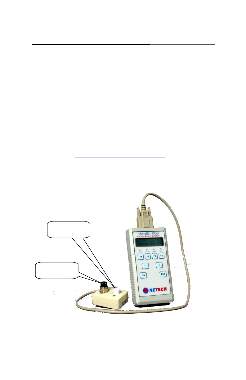
MicroSim Cardiac Output Simulator Shown with
Baxter Edwards compatible Interface Cable
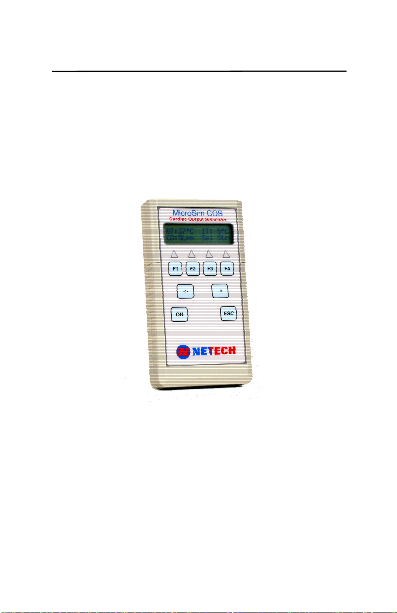
2.2 Instrument Familiarity
Injectate
Temp
Blood Temp

10
2.3 Controls and Menu Structure
Controls
The control consists of four function keys F1 – F4, a left arrow
(<), a right arrow (>), Esc key and power On/Off.
Each function key is active based on the context of each menu.
Function keys are assigned to selections appearing along the
bottom line of the display. When there are more selections than
can fit on one screen, left and right arrows will be displayed, and
the arrow keys become active to permit scrolling of selections.
For most menus, the Esc key returns you to the Main Screen
without making any selections. The display consists of a 16x2
character LCD display. The menu structure is as follows.
Initialization Menu
On power-up, the initialization screen will appear:
N
E
T
E
C
H
C
O
S
2
0
0
0
Internal tests are performed during power on initialization, If all
initialization tests pass, the unit will move on to the Simulator
Main menu as below.
Simulator Main Screen
B
T
: 3
7
°
C
I
T
: 5
°
C
C
O
: 5
L
p
m S
e
l S
t r
F3
F4
Menu Abbreviations:
BT: Blood Temperature
IT: Injectate Temperature
CO: Cardiac Output
Sel: Selection menu
Str: Start waveform
Active selection keys in the Main Screen are F3 and F4:
(F3): Selects other CO values.
The default value is set at 5 LpM.
(F4): Starts the CO waveform.
Press (F4) to start simulation. A progress bar will appear at the

11
lower right as simulation starts. It provides a visual indication of
the percentage of the elapsed waveform. During a simulation,
the COS will not respond to any keys pressed. To show the
simulation has completed, the progress bar will become a series
of dashes as shown:
B
T
: 3
7
°
C
I
T
: 5
°
C
C
O
: 5
L
p
m - - - - - - -
Pressing F3, F4, or Esc will reset the simulator and return to the
Main Screen.
Selection Menu
Press (F3) ‘Sel’ from the Main Screen to enter the Selection
Menu:
S
e
l e
c
t i o
n
C
O
I
T
B
T
C
f g
F1 F2 F3 F4
Active keys in the Selection Menu:
• CO (F1): Enters the CO rate selection menu.
• IT (F2): Enters the Injectate Temperature selection menu.
• BT (F3): Enters the Blood Temperature selection menu.
• Cfg (F4): Enters the Configurations menu.
• Esc: Returns to the Main Screen.
CO Output Selection Menu
C
O
r a
t e
: 5
L
p
m
<
3
5
6
7
>
F1 F2 F3 F4
C
O
r a
t e
: 5
L
p
m
<
5
C
a
l >
F1
In the CO Rate menu, four CO rate wave types are available in
Liters per minute: 3, 5, 6, and 7. 5Cal is a 5Lpm square wave
calibration output. The current setting is displayed. Selecting a
new value returns you to the Main Screen. Press Esc to leave
the current setting unchanged.

12
Injectate Temperature Select Menu
I
n
j . t e
mp
: 5
°
C
5
2
0
F1 F2
Injectate Temperature selections simulate the resistance of a
Coset Probe thermistor. The two selections available are 5°C
and 20°C. The current setting is displayed. Selecting a new
value returns you to the Main Screen. Press Esc to leave the
current setting unchanged.
Blood Temperature Select Menu
B
l o o d t e m p : 3
7
° C
3
7
3
8
F1 F2
Blood temperature selections simulate the resistance of an ideal
Catheter thermistor. The two selections available are 37°C
(98.6°F) and 38°C (100.4°F). The current setting is displayed.
Selecting a new value returns you to the Main Screen. Press
Esc to leave the current setting unchanged.
Configuration Menu
C
o n
f i g M e n
u
<
S a v V
e r M d l P
N
>
F1 F2 F3 F4
C
o n
f i g M e n
u
<
R
O
M E P
>
F1 F2
Active keys in the Config Menu:
• Sav (F1): Allows you to save the current combination of CO
Rate, BT, and IT as the power-up defaults.
Service related selections:
• Ver (F2): Displays firmware version identification.
• Mdl (F3): Displays machine model identification.
• PN (F4): Displays machine Part No. identification.

13
Diagnostic selections:
• ROM (F1): Performs a ROM checksum to verify the integrity of
the processor's memory. A pass/fail message will display. This
function is also performed on power-up.
• EP (F2): Performs a non-volatile memory (EEPROM) checksum
to verify the integrity of the machine calibration constants. A
pass/fail message will display. This function is also performed on
power-up.
Notes on proper operation
• When a change in temperature selection is made (either Blood
Temp. or Inj. Temp.), the simulated resistance outputs
experience a small amount of fluctuation. For best results, allow
10 seconds for the baseline to stabilize before starting a
simulation.
• The battery voltage is continually monitored during normal
operation. If a low battery condition is detected, a “LOW
BATTERY” message will appear and all functions will be
disabled.

14
2.5 Operating COS
1. Connect the MICROSIM COS to the monitor under test,
using the correct interface cable.
2. Set the Computation Constant to 0.542 on the patient
monitor.
3. Turn the MICROSIM COS On.
4. Select the desired blood temperature, injectate temperature,
and CO rate settings as outlined in section 2.3.
5. Allow 10 seconds for the baseline to stabilize.
6. Press the Start button on the monitor under test.
7. Press Str (F4) on the MICROSIM COS to begin a waveform
simulation.
8. When the test is complete, verify the reading on the patient
monitor.
9. Repeat steps 4 through 8 for other values of blood temp.,
injectate temp., and CO rates.

15
Trouble Shooting Section 3
3.1 Error Codes
• Error 1: Low Battery.
Display reads, “Low Battery”, “Turn unit off.” The battery
voltage has fallen below the safe operating limit and all
functions have been disabled. Turn off the unit and replace
the battery.
• Error 2: ROM Checksum error.
A fault has been found in the processor’s permanent
memory. This is a fatal error, the unit should be returned to
the factory for service.
• Error 3: EEPROM Checksum error.
A fault has been found in the Non-Volatile Memory storage.
This is a fatal error, the unit should be returned to the factory
for service.
• Error 4: Cal jumper short.
This is a calibration procedure error. It is meant as a
reminder to disable calibration before leaving a calibration
lab. If this error should appear during normal operation, an
internal fault condition may exist and the unit should be
returned for service.
• Error 5: Coeffs invalid.
The calibration coefficients may have become corrupted. If
this error appears, enter the Configuration Menu described
in section 2.3 and select EP (F2). This will test the
readability of the EEPROM contents. Cycle power. If this
error persists, the unit will have to be considered out of
calibration and should be returned for service.
• Error 6: DCP out of tolerance.
This error can only be set during a calibration. It is meant as
a troubleshooting aid during service and can not be set
during normal operation.
16
Appendix Section 4
Table of contents
Other Netech Medical Equipment manuals


Popular Medical Equipment manuals by other brands

Beurer
Beurer PO 45 manual

AMI
AMI SMARTY SAVER user guide

Gima
Gima 27622 User manual & assembly instructions

Villa Sistemi Medicali
Villa Sistemi Medicali Rotograph EVO 3D Service manual

Siemens
Siemens MOBILETT Plus HP Installation and setting instructions

Atlantic Therapeutics
Atlantic Therapeutics INNOVO Instructions for use


Costcare
Costcare L440C user manual

Dräger Medical
Dräger Medical Narkomed GS Operator's instruction manual

Invacare
Invacare Platinum Series user manual

VISIOMED
VISIOMED My ECG Bewel connect+ BW-HR1 manual

Aquatec
Aquatec 4.03.002 operating instructions

Pressalit Care
Pressalit Care R8478 Mounting instruction