DEGREE CONTROLS B-Series User manual

B-Series Air Velocity Sensors USER GUIDE 67500MN00-A01
B-Series Air Velocity Sensors USER GUIDE 67500MN00-A01 1
B-Series Air Velocity Sensors
User Guide
DEGREE CONTROLS, INCORPORATED
18 Meadowbrook Drive
Milford, New Hampshire 03055 USA
Degree Controls, Inc. © Copyright 2018, all rights reserved.
Information in this document is subject to change without notice.
Windows® is a registered trademark of Microsoft Corporation • All other trademarks are property of their respective owners.

B-Series Air Velocity Sensors USER GUIDE 67500MN00-A01
B-Series Air Velocity Sensors USER GUIDE 67500MN00-A01 2
Table of Contents
1General Information ................................................................................................................................................................................................ 3
1.1 Overview ...................................................................................................................................................................................................................3
1.2 Features.....................................................................................................................................................................................................................3
1.2.2 Electrical & Performance Features..................................................................................................................................................................3
1.2.1 Mechanical Features .......................................................................................................................................................................................3
2Product Specifications..............................................................................................................................................................................................4
2.1 General Specifications ...............................................................................................................................................................................................4
2.2 Model Specifications .................................................................................................................................................................................................5
2.3 Hardware Configuration............................................................................................................................................................................................5
3Wiring Information ..................................................................................................................................................................................................6
3.1 Configured with Analog Output and UART Digital Communication...........................................................................................................................6
3.2 Configured Only with UART Output ..........................................................................................................................................................................6
3.3 Configured Only with I2C Output...............................................................................................................................................................................6
4Mechanical Information...........................................................................................................................................................................................7
4.1 Probe Sensor Head Mechanical Drawings .................................................................................................................................................................7
4.2 °C Clamp Mechanical Drawing...................................................................................................................................................................................7
5Mounting and Positioning ........................................................................................................................................................................................ 8
5.1 Probe Style Sensors: B300/B500 ...............................................................................................................................................................................8
5.1.1 Gland Installation ............................................................................................................................................................................................8
5.1.2 °C Clamp Installation.......................................................................................................................................................................................9
5.1.3 Airflow Direction ...........................................................................................................................................................................................10
6Communication...................................................................................................................................................................................................... 10
6.1 UART........................................................................................................................................................................................................................10
6.1.1 Hardware.......................................................................................................................................................................................................11
6.1.2 Configuration ................................................................................................................................................................................................11
6.2 I2C............................................................................................................................................................................................................................12
6.2.1 Configuration ................................................................................................................................................................................................12
6.3 Velocity Analog Output (Voltage)............................................................................................................................................................................13
6.3.1 Velocity Analog Output (Voltage) Example ...................................................................................................................................................15
6.4 Velocity Analog Output (Current)............................................................................................................................................................................16
6.4.1 0-20 mA.........................................................................................................................................................................................................16
6.4.2 4-20 mA.........................................................................................................................................................................................................16
6.4.3 Velocity Analog Output (Current) Example ...................................................................................................................................................17
6.5 Temperature Analog Output ...................................................................................................................................................................................17
6.5.1 Temperature Analog Example.......................................................................................................................................................................18
7Sensor Registers..................................................................................................................................................................................................... 19
7.1 Memory Map...........................................................................................................................................................................................................19
8Degree Controls Inc. Product Warranty .................................................................................................................................................................. 23

B-Series Air Velocity Sensors USER GUIDE 67500MN00-A01
B-Series Air Velocity Sensors USER GUIDE 67500MN00-A01 3
1 General Information
1.1 Overview
Thank you for your purchase of a DegreeC B-Series Sensor,
a versatile and rugged, high-performance air velocity sensor
that measures real-time air velocity and directionality values in
both analog and digital communication outputs.
Designed with conformal coated electronics and sealed enclosures, our Sensor Products are suitable for demanding
applications, including those in corrosive or alkaline environments. With their robust, splash proof design and UV
tolerant construction, the B-Series sensors are designed to handle a wide range of product and process control air flow
applications. Additionally, the B-Series is configured to order, with a variety of velocity ranges, mechanical lengths, and
output communication styles available.
1.2 Features
1.2.1 Mechanical Features
• Two available mounting styles: Standard clamp
or special gland fitting used for mounting sensor
assembly, without need for screws, or hands
inside the duct.
• Optimized flow geometry with segregation of
velocity and temperature elements for highest
accuracy.
• Aerodynamic cross section to minimize flow
disturbance.
• Robust, sealed probe assembly uses corrosion
and UV resistant materials.
• Printed insertion depth markers and flow
direction arrow.
• Conformal coated sensing elements for
environmental protection.
• Plenum-rated cabling suitable for HVAC,
laboratory and process control applications.
• Remote head models available for compact
applications or design-in embedded sensing
needs.
• RoHS compliant
• Certified European (CE)
1.2.2 Electrical & Performance Features
• Industry-leading air velocity performance, with
repeatability within ±1%.
• Quick Average velocity reading for fastest
control system response.
• Wide voltage input options 4.5 –15VDC or
24VAC/DC.
• Multiple digital outputs available.
• Multi-sensor addressing capability.
• Intelligent, built-in customizable
averaging/smoothing functions.
• <10 second start-up time and 400ms response
time.
• May be configured as an airflow switch with
open drain output.
• Both air velocity and temperature analog
outputs may be configured as voltage or
current.

B-Series Air Velocity Sensors USER GUIDE 67500MN00-A01
B-Series Air Velocity Sensors USER GUIDE 67500MN00-A01 4
2 Product Specifications
2.1 General Specifications
Operating Temperature
0°C to 60°C (32°F to 140°F)
Storage Temperature
-40°C to 105°C (-40°F - 221°F)
Air Velocity Range
-20m/s to +20m/s (-4000 fpm to +4000 fpm)
Relative Humidity
5 –95%
Repeatability
± 1% of reading (under identical conditions)
Temperature Accuracy
± 1°C*
Response Time
400ms
Airflow Averaging Time
Configurable (3 second default)
Start-up Time
<10 s
Velocity & Temperature Output
0-5V or 0-10V, 0-20mA or 4-20mA output
Digital Output
UART or I2C available for flow and temperature info.
Alarm Output
Open drain, configurable trip point
Communication
I2C (400KHz) or 3.3V UART
Cable Length
2 m (6 ft.)
Housing Construction
Polycarbonate (PC), UL94-V0 (head), UL94-HB (housing)
Plenum Rated Cable
22 AWG
Environmental Protection
IP65 electronics, including conformal coated sensing element
Standard Dimension
Selectable lengths (See Section 2.3, Length)
*The air velocity sensor uses a hot bead algorithm, and at low velocities, the error in air temperature measuring grows due to self-
heating effects. The air temperature accuracy is specified as a function of velocity:
at velocities > 0.5 m/s [100 fpm] = ±1 ˚ C [1.8 ˚ F]
at velocities < 0.5 m/s [100 fpm] = ±2 ˚ C [3.6 ˚ F]
Temperature Compensation: The B-Series is a thermal airflow sensor; it is sensitive to changes in air density and indicates velocity
with reference to a set of standard conditions (21°C (70°F), 760mmHg (101.325kPa), and 0%RH). The B-Series has been designed so
that when used over the stated temperature compensation range, the sensor indicates very close to actual air velocity and minimal
compensation is only required to account for changes in barometric pressure or altitude.
Range
Accuracy*
Deadband**
-1.0 to 1.0 m/s (-200 to 200 fpm)
± (1% of reading + 0.05 m/s [10 fpm])
-0.15 to 0.15 m/s (-30 to 30 fpm)
-10 to 10 m/s (-2,000 to 2,000 fpm)
± (4% of reading + 0.10 m/s [20 fpm])
-0.5 to 0.5 m/s (-100 to 100 fpm)
-20 to 20 m/s (-4,000 to 4,000 fpm)
± (5% of reading + 0.15 m/s [30 fpm])
-1.0 to 1.0 m/s (-200 to 200 fpm)
*within compensation range
**range of velocities where the direction and velocity are not discernible by the sensor
General Specifications Table 1: Air Velocity Performance

B-Series Air Velocity Sensors USER GUIDE 67500MN00-A01
B-Series Air Velocity Sensors USER GUIDE 67500MN00-A01 5
2.2 Model Specifications
Degree Controls offers two models of the B-Series Air Velocity Sensor. The choice of model depends on the user’s
voltage range and current requirements, as noted below:
Name
Input Voltage Range
Current Consumption
B300
4.5 –15VDC
< 100mA nominal @ 12V
B500
24VAC/DC ± 20%
< 65mA nominal @ 24V
Model Specifications Table 1: Input Voltage Range & Current Consumption
2.3 Hardware Configuration
Length
1 = 203mm [8.0”]
max insertion depth = 160mm [6.3”]
2 = 305mm [12.0”]
max insertion depth = 263mm [10.4”]
Velocity Profile
A = -1.0 to 1.0 m/s (-200 to 200 fpm)
B = -10 to 10 m/s (-2,000 to 2,000 fpm)
C = -20 to 20 m/s (-4,000 to 4,000 fpm)
Output Configuration
1 = 0 –5 VDC air velocity output
2 = 0 –5 VDC air velocity and air temperature (dual
outputs)
3 = 0 –10 VDC air velocity output
4 = 0 –10 VDC air velocity and air temperature (dual
outputs)
5 = 0 - 20 mA air velocity
6 = 0 - 20 mA air velocity and air temperature (dual
outputs)
7 = 4-20 mA air velocity
8 = 4-20 mA air velocity and air temperature (dual
outputs)
9 = UART communication
Hardware Configuration Table 1: Ordering Information

B-Series Air Velocity Sensors USER GUIDE 67500MN00-A01
B-Series Air Velocity Sensors USER GUIDE 67500MN00-A01 6
3 Wiring Information
3.1 Configured with Analog Output and UART Digital Communication
Wire Color
Wire Gauge
Description
Red
22 AWG
Power
Black
Ground
White
Velocity Analog Output
Green*
Temperature Analog Output
Orange
UART Receive (RX)
Blue
UART Transmit (TX)
Brown**
Open Drain Alarm
*Only for dual analog
**While the B300 and B500 can be configured as open drain switches; please see the Switch Series manual for
purpose-built airflow switches.
3.2 Configured Only with UART Output
Wire Color
Wire Gauge
Description
Red
22 AWG
Power
Black
Ground
White
UART Receive (RX)
Green
UART Transmit (TX)
3.3 Configured Only with I2C Output
Wire Color
Wire Gauge
Description
Red
22 AWG
Power
Black
Ground
White
SCL
Green
SDA
Notes:
1. For I2C communication, external pull-up resistors to +3.3V for SDA and SCL are required. The B300/B500
does not have internal pull-up resistors.
2. For RS232 communication, an external level shifter is required to convert 3.3V TTL to RS232 voltage
levels. The B300/B500 RX and TX signals are 3.3V TTL.
Caution:
The B300/500 sensors do not have polarity protection. Do not connect positive voltage to ground lead.
B-Series Air Velocity Sensors USER GUIDE 67500MN00-A01
B-Series Air Velocity Sensors USER GUIDE 67500MN00-A01 7
4 Mechanical Information
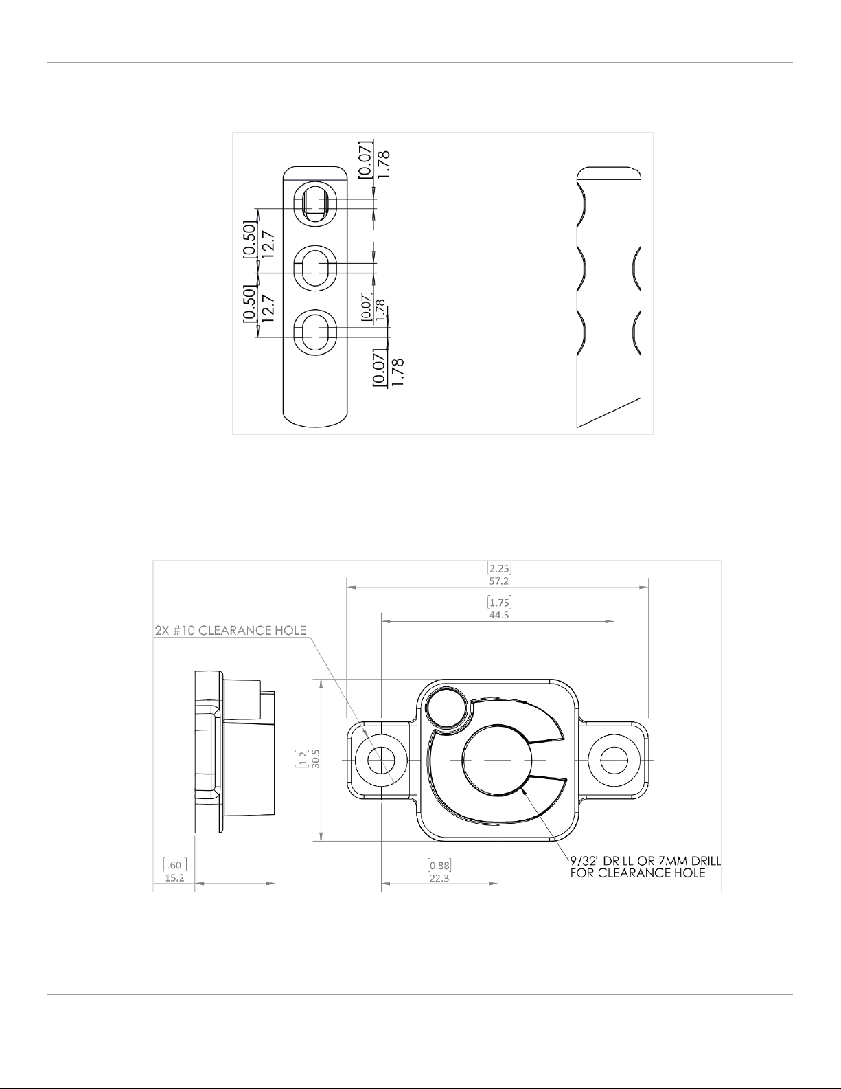
4.1 Probe Sensor Head Mechanical Drawings
4.2 °C Clamp Mechanical Drawing
Mechanical Figure 2: °C Clamp
Note: [inch]mm
Mechanical Figure 1: B-Series Sensor Head
Note: [inch]mm

B-Series Air Velocity Sensors USER GUIDE 67500MN00-A01
B-Series Air Velocity Sensors USER GUIDE 67500MN00-A01 8
5 Mounting and Positioning
5.1 Probe Style Sensors: B300/B500
Mounting Figure 1: Sensor Dimensions
Note: Multiple sensor lengths are available to accommodate insertion depths of 30mm [1.25"] to 245mm [9.6"]. See Mounting
Figure 1 above for insertion "zero point" datum.
The B-Series Sensor utilizes either a °C Clamp or Gland fitting for installation. Please follow the below instructions for
optimal installation:
5.1.1 Gland Installation
1. Drill a 7/8” 0.75” (20mm) hole into the surface you wish to install the Sensor into.
• Follow the below instructions to install the Sensor via Gland Fitting.
2. Adjust the Sensor’s insertion depth (use the printed ruler on the
Sensor’s body for reference), and tighten the gland nut onto
the Sensor body (“A” in Figure 2 below).
3. Insert the Sensor into the drilled hole wider flange first
(“B” in Figure 2 below), then rotate into position, ensuring that the
sensor is facing the intended direction.
4. Tighten the mounting nut (“C” in Figure 2 below) in the left-hand
direction.
Mounting Figure 2: Gland Nut
B-Series Sensor with Gland Fitting
A
C
Front View
Side View
B
B-Series Air Velocity Sensors USER GUIDE 67500MN00-A01
B-Series Air Velocity Sensors USER GUIDE 67500MN00-A01 9
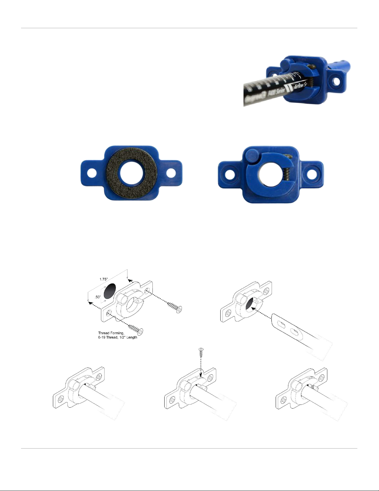
5.1.2 °C Clamp Installation
1. Drill a 7/8” 0.75” (20mm) hole into the surface you wish to install the Sensor into.
• Follow the below text instructions along with the visuals in
Figure 4 to install the °C Clamp.
2. Peel off the adhesive backing on the back of the °C Clamp (see Figure
3 below) and place onto the drilled hole. Using the provided screws,
tighten the °C Clamp on the right and left side to the surface.
3. Insert the Sensor into the hole of the °C Clamp and adjust the
Sensor’s insertion depth (use the printed ruler on the Sensor’s body
for reference), ensuring that the sensor head (see section 5.3
Airflow Direction) is facing the intended direction.
4. Using the provided screw, tighten the °C Clamp onto the Sensor body.
Mounting Figure 3: °C Clamp
Mounting Figure 4: °C Clamp Installation
B-Series Sensor with °C Clamp Fitting
Back View Front View
Step 1
Step 2
Step 4
Step 5
Step 3

B-Series Air Velocity Sensors USER GUIDE 67500MN00-A01
B-Series Air Velocity Sensors USER GUIDE 67500MN00-A01 10
5.1.3 Airflow Direction
To ensure that the Sensor performs within its published specifications, proper mounting precautions must be followed:
• The central airflow cavity that surrounds the flow thermistor must be orientated perpendicular to the airflow
being monitored.
• When monitoring air velocity within a pipe or duct, mount the sensor so that the main flow cavity is in the
center of the pipe or duct. Avoid mounting the sensor in turbulent locations caused by elbows, duct size
changes, etc. If airflow turbulence causes excessive airflow reading variation, increasing the Sample Time (index
63)may solve the problem.
Airflow Figure 2: Direction of Airflow
6 Communication
The B-Series Sensors support two methods of communication: UART and I2C. The choice of communication is set up at
DegreeC prior to shipment.
6.1 UART
The communication protocol described below is for communication between a master host and the slave Sensor
product. This protocol is used to read/write configuration variables and to read process variables from the Sensor.
• The host can configure the Sensor by transmitting a “Memory Write” command which contains the memory
index and the new data within the command.
• The host reads configuration variables using the “Memory Read” command.
• For multi-byte configuration variables, the data format is “little endian”. The lowest address is the least
significant byte.
Four process system variables (Velocity, Tamb, Power, and Raw Velocity) can also be read from the Sensor using the
“Read Velocity”, “Read Tamb”, “Read Power”, and “Read Raw Velocity” commands, as noted in the figure below:

B-Series Air Velocity Sensors USER GUIDE 67500MN00-A01
B-Series Air Velocity Sensors USER GUIDE 67500MN00-A01 11
Byte
1
2
3
4
1
2
3
4
Read
Velocity
1
0
0
checksum
Velocity
(Hi)
Velocity
(Lo)
0
checksum
Read
Tamb
2
0
0
checksum
Tamb
(Hi)
Tamb
(Lo)
0
checksum
Read
Power
3
0
0
checksum
Power
(Hi)
Power
(Lo)
0
checksum
Memory
Write
6
Memory
Index
Data
checksum
Memory
Index
Data
0
checksum
Memory
Read
7
Memory
Index
0
checksum
Memory
Index
Data
0
checksum
Read Raw
Velocity
9
0
0
checksum
Velocity
Raw
(Hi)
Velocity
Raw
(Lo)
0
checksum
RESET
12
0
0
checksum
n/a
n/a
n/a
checksum
UART Figure 1: Process System Variables
6.1.1 Hardware
The Sensor’s UART RX and TX signals are digital signals from the internal processor’s UART at 3.3V TTL voltage levels.
To convert to true RS232 signals, an external level shifter is required.
6.1.2 Configuration
UART configuration is fixed at 19200 baud rate, 8 data bits, no parity, 1 stop bit.
Protocol
The sensor is a slave device and supports several different commands. Both transmit and reply command message
lengths are four bytes. The fourth byte is a checksum byte to verify message integrity. The checksum byte is determined
by performing an “exclusive or” logic operation of the first three bytes. The tables below define the seven host
commands supported and the appropriate sensor reply.
Password Protection
Memory locations designated as (RWP) in the Memory Map require two consecutive Memory Write commands to
change the setpoint.
• Command #1: Memory Write 0xAA to the Password (index 83).
• Command #2: Memory Write the new value to the password protected register. If valid, Sensor will accept the
commands and write the new value. The Password (index 83) is automatically reset to 0xFF, the protected
default state.
Caution:
• If the sensor receives a message with an invalid command byte or an invalid checksum, the message will be
discarded and the Sensor will not reply.
• If the sensor receives a partial message, the message will be discarded and the Sensor will not reply.
• The host should use the “Read Velocity”, “Read Tamb”, “Read Power”, and “Read Raw Velocity” commands
to read these double byte variables.
• When reading the double byte process variables Velocity (index 67), Raw Velocity (index 69), T Ambient
Temperature (index 71), T Flow Temperature (index 73), Power Average (index 75), using the single byte
“Memory Read” command, read the Low Byte first, then read the High Byte. This prevents a “byte
mismatch” reading error.

B-Series Air Velocity Sensors USER GUIDE 67500MN00-A01
B-Series Air Velocity Sensors USER GUIDE 67500MN00-A01 12
6.2 I2C
The communication protocol described below is for communication between the I2C master host and the I2C slave
Sensor. This protocol is used to read/write configuration variables and to read process variables from the Sensor.
Reading and writing to the Sensor uses the same protocol that is commonly used to read and write to EEPROM’s.
For multi-byte configuration and process variables, the data format is “little-endian”, the low order byte of the number
is stored in memory at the lower address.
6.2.1 Configuration
The protocol sequence is as follows:
• Each sensor starts out with a default Address of 192. This address may be changed to an arbitrary 8-bit value by
writing to the sensor’s I2C address register and cycling power.
• The I2C commands for the Sensors are defined as per the following tables:
1
7
1
1
8
1
8
1
1
S
Slave
Addres
s
Wr
A
Sub
Addres
s
A
Data
Byte
A
P
S
=
Start bit
Slave Address
=
Sensor Address
Wr
=
0
A
=
Acknowledge from the
Sensor
Sub Address
=
Index into the Sensor’s
Memory Map
Data Byte
=
Data written to the sensor
at the Sub Address
P
=
Stop bit
I2C Figure 1: Write Byte
1
7
1
1
8
1
1
8
1
1
8
1
1
S
Slave
Addre
ss
Wr
A
Sub
Addre
ss
A
S
Slave
Addre
ss
Rd
A
Data
Byte
A
P
S
=
Start bit
Slave Address
=
Sensor Address
Wr
=
0
Rd
=
1
A shaded
=
Acknowledge from the sensor (0 to
indicate Ack)
Sub Address
=
Index into the sensor Memory Map
Data Byte
=
Data from the sensor at the Sub
Address
A non-shaded
=
Acknowledge from the Host (1 to
indicate end of read cycle)
P
=
Stop bit
I2C Figure 2: Write Byte

B-Series Air Velocity Sensors USER GUIDE 67500MN00-A01
B-Series Air Velocity Sensors USER GUIDE 67500MN00-A01 13
1
7
1
1
8
1
1
8
1
1
8
1
8
1
1
S
Slave
Address
Wr
A
Sub
Address
A
S
Slave
Address
Rd
A
Data
Lo
Byte
A1
Data
Hi
Byte
A2
P
S
=
Start bit
Slave Address
=
Sensor Address
Wr
=
0
Rd
=
1
A shaded
=
Acknowledge from the Sensor (0 to indicate Ack)
Sub Address
=
Index into the Sensor Memory Map
Data Byte Lo
=
Data from the sensor at the Sub Address
A1 non-shaded
=
Acknowledge from the Host (0 to indicate read cycle continues if reading a second
byte, 1 to indicate end of read cycle)
Data Byte Hi
=
Data at the next memory address (Only used if A1 was 0)
A2 non-shaded
=
Acknowledge from the Host (1 to indicate end of read cycle)
P
=
Stop bit
I2C Figure 3: Read Byte(s)
I2C Command Restrictions
• The write cycle only supports a single byte write cycle. Multiple byte write cycles are not supported.
• The read cycle supports a single and a double byte read cycle. Read cycles (greater than two) are not supported.
I2C Address
The sensor supports a 7-bit address which is shifted left to become the 7 most significant bits of the Slave Address Byte.
The default value (after shifting) is 0xC0 (192) for write operations and 0xC1 (193) for read operations. This base address
is password protected and can be changed by performing a “Write Byte” command to I2C Base Device Address (index 0)
with the new base address. The new base address will become active after the next power cycle.
Password Protection
Setpoints designated as (RWP) in the Memory Map require two consecutive I2C write commands to change the setpoint.
• Command #1: Write 0xAA to the Password (index 83).
• Command #2: Write the new value to the password protected register. If valid, the Sensor will accept the
commands and write the new value. The Password (index 83) is automatically reset to 0xFF, the protected
default state.
6.3 Velocity Analog Output (Voltage)
The sensor velocity is translated to an analog voltage with a configurable range. The output voltage that corresponds to
the Velocity High Range (index 52) is determined by setting Vout Maximum (index 59) to the desired voltage, units are in
millivolts. As the converted Velocity (index 67) goes from 0 mm/s to Velocity High Range (index 52), Vout goes from 0 to
Vout Maximum (index 59).
Output voltage functionality at velocities exceeding the Velocity High Range (index 52) is configurable by setting bit 0 of
the Config Flags (index 10). With bit 0 set to 0, Vout is clamped at Vout Maximum (index 59). With bit 0 set to 1, Voutput
is not clamped and will continue to rise in a linear fashion at Velocities exceeding the Velocity High Range (index 52).
Caution:
If there is a communication failure in the midst of a read/write sequence, it is NECESSARY to issue a “Stop” bit
before resuming communication with a new “Start” bit.

B-Series Air Velocity Sensors USER GUIDE 67500MN00-A01
B-Series Air Velocity Sensors USER GUIDE 67500MN00-A01 14
By default, bit 0 of the Config Flags (index 10) is set to 0 (clamped). See Figure 1 below for the Voutput functionality as
bit 0 is set to 0 (clamped) and 1 (not clamped):
Velocity Analog Output Figure 1: Voutput (0 –5V) with and without Clamping
Note: Velocities below -Velocity Maximum are always clamped to 0V.
For sensors without communications, the velocity can only be determined by measuring Voutput and calculating the
velocity per the equation in Figure 2 below:
Velocity Analog Output Figure 2: Velocity Calculation Equation using Voutput
The Velocity High Range and Vout Maximum can be obtained from the B-Series Part Number. For example, if the sensor
model is “B300–2–A–1”, the Velocity High Range is 1000 mm/s (1.0 m/s) and the Vout Maximum is 5V. In this case,
if Vout is 3VDC, then the velocity can be calculated per the following equation:
Velocity is therefore 0.2 m/s.
Velocity Analog Output Figure 3: Velocity Calculation Example with Vout = 3V

B-Series Air Velocity Sensors USER GUIDE 67500MN00-A01
B-Series Air Velocity Sensors USER GUIDE 67500MN00-A01 15
Voutput: The Voutput value of the B300/500 sensor can also be obtained by the host reading Voutput (index 77) via the
communication port. Units are in (mv).
6.3.1 Velocity Analog Output (Voltage) Example
Note: By default, DegreeC sensors are calibrated in metric format.
• Application airflow range is -10m/s –10 m/s.
• Output Voltage at 10 m/s is 5.0V.
• At airflow velocities exceeding 10m/s, the output voltage should not exceed 5.0V
(Note: Only if Config Flags [register 10] bit 0 != to 0.).
For this application, the Velocity Range of -10 –10 m/s specifies a type “B” Velocity Profile, and the voltage of 5.0V
specifies an Output Configuration Type “1” or “3”. In this case let’s assume this is an air velocity only output with an 8.3”
tube, so the appropriate model is “B300-3-B-1”. Figure 4 illustrates the Vout vs Velocity for this sensor model. Table 1
below lists the internal register configuration for this model:
Name
Index
(decimal)
Value
Description
Configuration Flag
10
0b00000000
Please see section 7.1, Memory Map
Velocity Deadband Limit
50,51
500
Standard Velocity Low Range of 500 mm/s
Velocity High Range
52,53
10000
Standard Velocity High Range of 10000 mm/s
Vout Maximum
59,60
5000
Sets Vout maximum when Velocity equals
Velocity High Range
Velocity
67,68
6000
Velocity of last conversion is 6000 mm/s
Voutput
77,78
4000
Vout in (mv)
Velocity Analog Output Table 1: Internal Memory Map Parameters for Analog Out Example
Caution:
• Vout accuracy specification is only valid within the specified operational airflow range of the B300 and B500
and outside of their deadband. See General Specifications Table 1: Air Velocity Performance
• With the Voutput “not clamped”option, the output voltage is NOT limited to Vout Maximum.
B-Series Air Velocity Sensors USER GUIDE 67500MN00-A01
B-Series Air Velocity Sensors USER GUIDE 67500MN00-A01 16
6.4 Velocity Analog Output (Current)
6.4.1 0-20 mA
Velocity Analog Output Figure 5: 0-20 mA Example
Velocity Analog Output Figure 6: 0-20 mA Calculation Equation
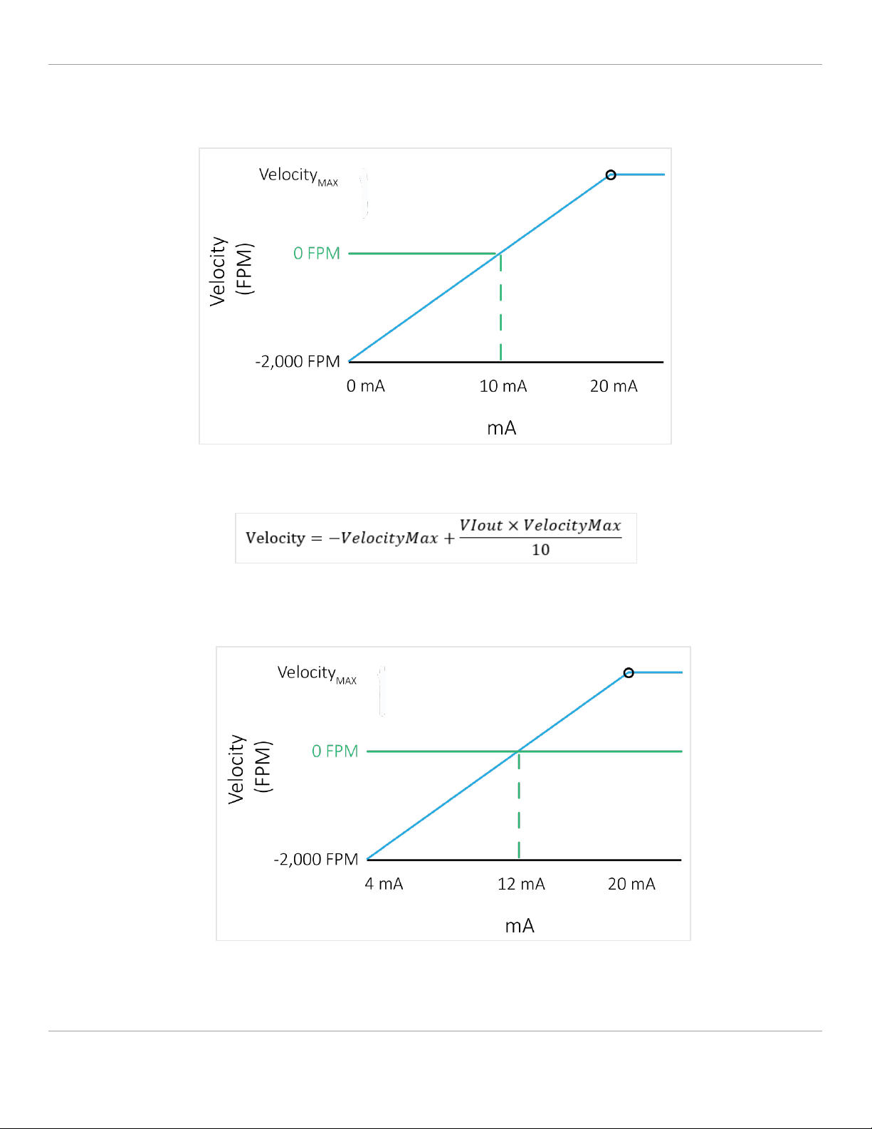
6.4.2 4-20 mA
Velocity Analog Output Figure 7: 4-20 mA Example

B-Series Air Velocity Sensors USER GUIDE 67500MN00-A01
B-Series Air Velocity Sensors USER GUIDE 67500MN00-A01 17
Velocity Analog Output Figure 8: 4-20 mA Calculation Equation
6.4.3 Velocity Analog Output (Current) Example
For a B Cal. Range solution when utilizing 4-20 mA output, simply plug in the values found in the Calibration Range Chart
below:
If the mA reading 8 mA for example:
• B Cal. Range Vout Maximum is 10 m/s
Plug in the numbers into the 4-20 mA formula as follows:
Velocity = −10 m/s + (8 mA − 4)×10 m/s
8
Velocity is therefore -5 m/s.
Velocity Analog Output Table 2: Calibration Range Table
Note: If the current outputs are unable to drive the desired current AND the sensor is configured for current out (i.e.
Config Flags [Index 10] bits 1 and 2 have not been set), bit 6 in Memory Location 66 will be set. (However, only if the
current output error bit is set in the config. register).
6.5 Temperature Analog Output
The sensor temperature is translated to an analog voltage with a fixed range. The output voltage that corresponds to the
Temperature High Range (100 °C) is determined by setting Tout Maximum (index 61) to the desired voltage, units are in
millivolts. As the converted T Ambient Average (index 71) goes from 0 °C to 100 °C, Tout goes from 0 to Tout Maximum
(index 61). The linear conversion graph for the (0 - 5V) and the (0 –10V) ranges are displayed on the following page:
Calibration Range
VOUT Max
A
1.0 m/s
B
10.0 m/s
C
20.0 m/s

B-Series Air Velocity Sensors USER GUIDE 67500MN00-A01
B-Series Air Velocity Sensors USER GUIDE 67500MN00-A01 18
Temperature Analog Output Figure 1: Toutput for (0 –5V) and (0 –10V)
Note: If Register 10 Bit 3 is set, the temperature is scaled from -25°C to 75°C.
For sensors without communications the temperature can only be determined by measuring Tout and calculating the
temperature per the equation below:
Temperature Analog Output Figure 2: Temperature Calculation Equation
Tout: The Tout value of the B3/500 sensor can also be obtained by the host reading Toutput (index 79) via the
communication port. Units are in (mv).
6.5.1 Temperature Analog Example
Requirements:
• Application temperature range is 0 –100 °C.
• Output Voltage at 100°C should be 5.0V.
In this example, the Tout signal measures 1.418 VDC. The equation below calculates the corresponding temperature.
The table below lists the internal register configuration for this model:
Temperature (°C) = Tout * TemperatureRange(°C)
ToutMaximum(VDC) =Tout * 100
ToutMaximum(VDC)
Caution:
• Tout accuracy specification is only valid within the specified operational temperature range of the sensor.

B-Series Air Velocity Sensors USER GUIDE 67500MN00-A01
B-Series Air Velocity Sensors USER GUIDE 67500MN00-A01 19
Temperature Analog Output Figure 3: Tout vs Temperature Example
Name
Index
(decimal)
Value
Description
Tout Maximum
61,62
5000
Sets Tout maximum when Temperature
equals Temperature High Range (100 °C)
T Ambient Average
71,72
2836
Temperature of last conversion is 28.36°C
Toutput
77,78
1418
Tout in (mv)
Temperature Analog Output Table 1: Internal Database Parameters for Temperature Analog Example
7 Sensor Registers
The sensor setpoints and process parameters can be accessed by reading and writing into the memory map using the
appropriate serial communications interface. The table below provides specific details for these parameters:
7.1 Memory Map
Index
Type
Size
Name/Description
Default
Dec
Hex
0
0x00
RWP
1
I2C Base Device Address: (used in I2C Communication Mode Only).
0xC0
1
0x01
RO
1
Communication Mode:
5=UART
6=I2C
per Model P/N
2
0x02
RW
1
Reserved for Alarm Upgrade
0
3
0x03
RW
2
Reserved for Alarm Upgrade
0
5
0x05
RW
2
Reserved for Alarm Upgrade
0
7
0x07
RW
1
Reserved for Alarm Upgrade
0
8
0x08
RW
1
Reserved for Alarm Upgrade
0
9
0x09
RW
1
Reserved for Alarm Upgrade
0
Temperature (°C)= =
Toutput * 100
Tout Maximum
1.418 * 100 = 28.36 °C
5

B-Series Air Velocity Sensors USER GUIDE 67500MN00-A01
B-Series Air Velocity Sensors USER GUIDE 67500MN00-A01 20
10
0x0A
RW
1
Configuration Flag: (bit mapped)
bit 0: 0=Vout clamped at VoutMaximum; 1=Vout NOT clamped at VoutMaximum
bit 1: 0=Vout set to 0v if sensor failure detected; 1=Vout set to VoutMaximum if sensor
failure detected
bit 2: 0=Tout set to 0v if ambient sensor failure detected; 1=Tout set to ToutMaximum if
ambient sensor failure detected
bit 3: 0 Tout Scaled from 0-100°C; 1: Tout Scaled from -25-75°C
bit 5: 0 0-20mA current out; 1: 4-20mA current out
bit 6: 0 enable current output error; 1: disable current output error
0
11
0x0B
RO
1
Calibrated (0=UNCALIBRATED, 1=CALIBRATED)
1
12
0x0C
RO
4
Reserved
ID Data
16
0x10
RO
4
Reserved
ID Data
20
0x14
RO
4
Serial Number: Combination of the Date Code (aka Year Week; Index 24), Work Order
(Index 30) number, and Serial Number (i.e. the order in which a particular sensor was
processed on a Work Order.
ID Data
24
0x18
RO
6
ID Data
30
0x1E
RO
4
ID Data
34
0x22
RWP
4
Multidrop UART Address: 1 Byte Identifier which can be used as an address for support of
multidrop UART communications protocol. A value of 0 means that mulitidrop messages will
be ignored. In order to set this byte, Sensor Power Average (address 75) must be over
35mW.
0
35
0x23
RO
1
Reserved
CAL Data
36
0x24
RO
1
Reserved
CAL Data
37
0x25
RO
1
Reserved
CAL Data
38
0x26
RO
4
Reserved
CAL Data
42
0x2A
RO
4
Reserved
CAL Data
46
0x2E
RO
1
Reserved
CAL Data
47
0x2F
RO
1
Tamb Velocity High Offset: Used to calculate Tamb, (sbbb.bbbb)
CAL Data
48/49
0x30
RO
2
Reserved
CAL Data
50
0x32
RO
2
Velocity Deadband Limit: From Model P/N, (mm/sec)
CAL Data
52
0x34
RO
2
Velocity High Range: From Model P/N, also used to determine V output, (mm/sec)
CAL Data
54
0x36
RO
1
Reserved
CAL Data
55
0x37
RO
1
Reserved
CAL Data
56
0x38
RO
1
Reserved
CAL Data
57
0x39
RO
1
Reserved
CAL Data
58
0x40
RO
1
Reserved
CAL Data
Table of contents
Popular Accessories manuals by other brands

AUSTRALIAN MONITOR
AUSTRALIAN MONITOR AMIS DI1 introduction

Panasonic
Panasonic MA3J700 Specification sheet

Yaohua Weighing System
Yaohua Weighing System XK3190-A23p user manual

Craftsman
Craftsman 944.511572 instruction manual

W4RT Electronics
W4RT Electronics ONE BOARD FILTER OBF-817 Installation

Orion
Orion 4411 quick guide


