Isotra VERANDA HRV52 User manual

MEASUREMENT AND ASSEMBLY MANUAL
Validity of the manual: 1. 3. 2018
1
VERANDA HRV52
1. INTRODUCTION
Veranda HRV52 is an outside sun protection to be fitted on top of the Veranda. This sun protection blocks the sun rays
and in doing so protects the veranda against overheating. Thanks to the special and manyfold fastening accessories, this
sun protection can be fitted onto all existing Veranda profiles..
Veranda has been designed as a sun protection and for that reason may not be used as an all-weather
protection. In case of heavy rain or wind the sun-blind has to be closed immediately. Therefore we recommend
to use the sun protection in combination wth an automated wind/sun –control.
2. GENERAL WARNINGS
For a safe fitting, use and maintenance of this sun protection a number of precautions have to be taken. For the
safety of everyone concerned, please do take notice of the following general warnings!
This manual is meant to be used by professionals only! It is not to be used by DIY-enthusiasts or apprentice fitters.
Before you start, please do read these instructions thoroughly.
The tightening of springs creates important powers. Be very careful and make sure of a solid footing whilst operating.
Provide sufficient light in the fitting area. Dispose of obstacles and dirt. Make sure that, except for the fitters, no other
people are in the fitting area. Unauthorized people might be in the way or at risk themselves.
Whilst operating the system, you must be able to overlook the complete area and the whole of the sun protection. There
are a number of places where people might get injured. Especially watch the following parts where people might risk
getting jammed: the extension pole, the intermediate rollers, the bench, the guide rails and the casing.
Electrical connections have to be made in accordance with the existing local norms and requirements.
3. LIST OF REQUIREMENTS
•Ladder
•Footplanks
•Wooden blocks 60x60x300 mm
•Electric drill
•Cross-head screwdriver
•Fork or ring spanners 13
•Tongs for clinch-nails
•Metal drill
•Ruler and pencil
•Voltmeter or test lamp 220 V
•Masonry drill 6 mm
•Clamps for electric wire
•Test cable with switch
•Socket wrench 4 mm

MEASUREMENT AND ASSEMBLY MANUAL
Validity of the manual: 1. 3. 2018
2
4. ASSEMBLY INSTRUCTIONS
4.1. OPENING THE PACKAGING
Take the bag of accessories, and divide the attachment points by the number of guide rails supplied. Make sure each
guide rail has the same number of supports.
The attachment points:
a. Standard aluminium supports
b. Higher aluminium supports
Push the hexagonal screws in the lateral guide and fix the aluminium supports. The gaps between the supports has to be
equal. Same procedure as the regular aluminium supports.
ATTENTION: The higher supports are only used for elevation and there is no guarantee that they absorb
sidelong pressures. Only use them in case of very stable Veranda profiles that cannot slip away. Provide if
necessary, in case of a larger pitch, per guide an extra connection to the wall or to the ground, in order to
prevent that the Veranda crashes forward.
Remark: In case of an intermediate roll, at the same time the screws are placed in the guide for the fixation of the support
for the intermediate roll.
4.2. SETTING UP THE LADDERS AND FOOTPLANKS
Position the ladders and set up the foot planks on the Veranda.
4.3. UNPACK THE BOXES
Take the boxes out of the packaging and lay them out in the right order on the roof of the Veranda.
4.4. CHECKING THE MEASUREMENTS
Check the dimensions of the Veranda against the Veranda profiles. Small deviations in measurements will be catched up
by the movable supports.
4.5. OUTLINING THE DIFFERENT POSITIONS
Using a completely prepared guide rail, mark on the roof where the supports are to be mounted. Take care: the distance
between the top support and the top end should be ca. 280 mm. Drill holes, for the base pieces of the supports, and screw
the supports tightly onto the Veranda frame.

MEASUREMENT AND ASSEMBLY MANUAL
Validity of the manual: 1. 3. 2018
3
4.6. POSITIONING THE WOODEN BLOCKS
Take a few blocks (60x60x300 mm.) and slide them under the mounting brackets between the boxes and the Veranda
profile.
4.7. CONNECTING THE BOXES
Take care that the spindles are matched to each other correctly.
The slots for the fabrics must be in line with each other. (avoid getting
dirty spots on the fabric). Insert the square connecting shaft one side
halfway into the side-hole. Check that the blind slot matches,
then insert the other half in the other hole. Now press the two halves
of the mounting bracket together and fix them by using the screws
supplied. Now screw the yellow slides against each other using the
small bolt and nut supplied. Each slide has a hole at the top for this
purpose. Only connect up in the right place.
Attention: Only couple the spindles as allowed. Given that the power of the motor is selected according to the number of
blinds to be operated, the number of blinds connected up must match the number allowed for the motor. For this reason,
end brackets not supplied with a connector are covered by a self-adhesive patch.
4.8. POSITIONING THE VERANDA
Slide the entire Veranda assembly over the wooden blocks up to the right position. (Which may be hard against the wall).
Take care that the Veranda profiles are at right angles regarding to the wall. We are working with a squared-off system.
4.9. UNWINDING THE CABLES
Unwind the cable so that there are no loops or kinks. Check that at least
2 or 3 turns of cable are left on the cable pulley. Mind that the cable
unrolls along the bottom side.
Connect the motor cable up provisionally using a test cable and let the
end profile run out for +/- 15cm.
4.10. POSITIONING THE CABLES INTO THE GUIDE RAILS
Take a guide rail and insert the cable across the entry pulley. Hold the
rail pointing diagonally downwards and push the cable through the rail.
Make sure that the cable comes out again through the right hole. At the
far end, feed the cable back round the pulley.

MEASUREMENT AND ASSEMBLY MANUAL
Validity of the manual: 1. 3. 2018
4
4.11. POSITIONING THE BOX AND THE GUIDE RAILS
Now lay the guide rails onto the glass roof, just in front of the pins of the mounting brackets. Make sure that the pins of the
mounting brackets on the box are in line with the guide rails.
4.12. POSITIONING THE CABLES INTO THE END PROFILE
Insert the cable into the endprofile, aside via the small hole behind the pulley on the slider Block.
4.13. POSITIONING THE CABLES
Lift the box and the end profile to the same height as the guide rails, and insert the end profile a short way into the rail.
Insert the pin of the mounting bracket into the aperture of the guide rail. Make sure that the cord and the carriage fit snugly.
Then pull the calbe at point E and the pin will automatically slide into the guide rail. Do the same for all the guide rails.
4.14. FIXING THE VERANDA IN THE SUPPORTS
Position the sun blind in the supports, and screw the supports hand-tight by using the screws supplied. Remove the
wooden blocks.
4.15. PLACEMENT OF THE INTERMEDIATE ROLLS
In case of using intermediate rolls, by extremely large extension, the brackets
are placed just underneath the guides. The intermediate rolls must be placed in
line to each other and rather in the middle of the lateral guide.

MEASUREMENT AND ASSEMBLY MANUAL
Validity of the manual: 1. 3. 2018
5
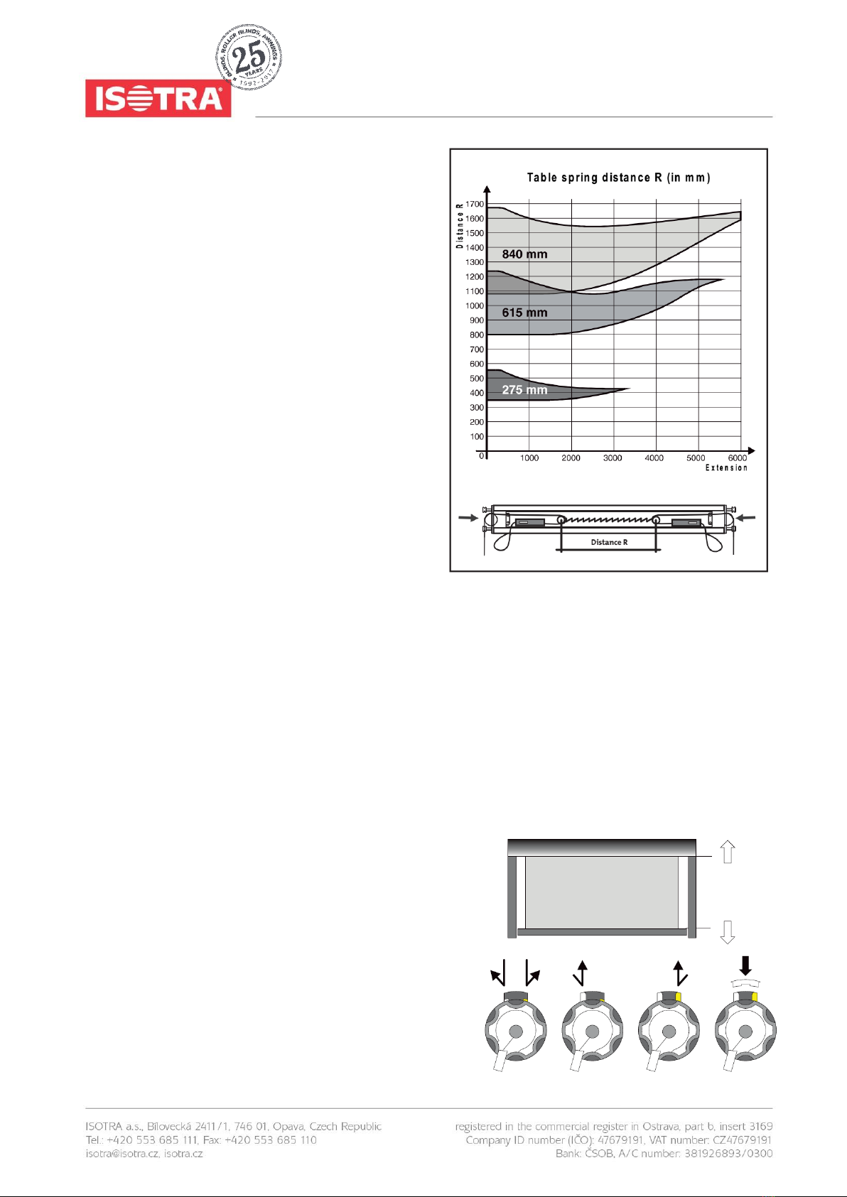
4.16. TENSIONING THE SPRING
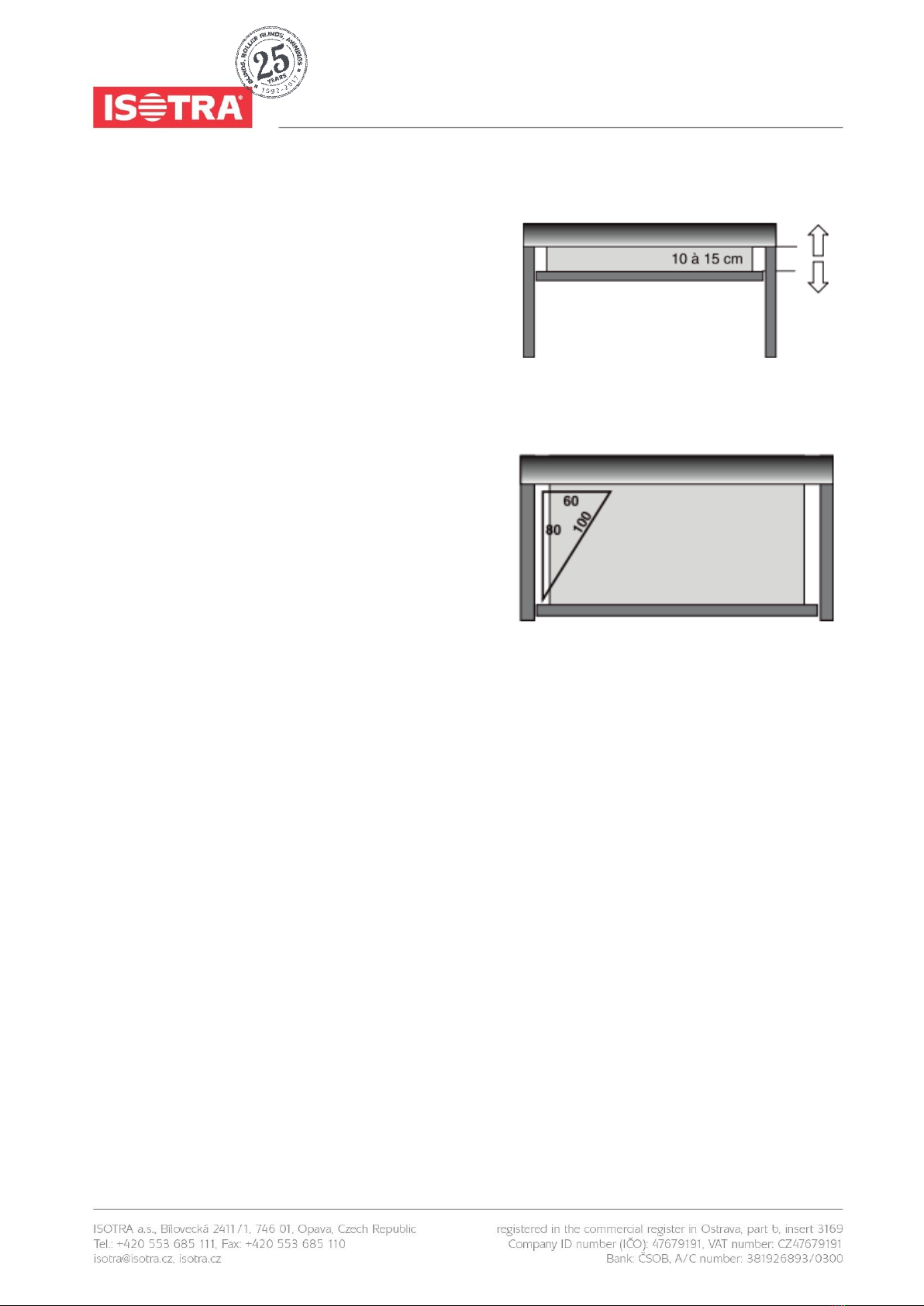
Position the end profile in the highest position and make 2
marks in the end profile the distance apart R
shown in the separate table.
The maximum distance depends on the spring supplied, the
used fabric, the diameter of the roll for
fabric and the extension of the blind.
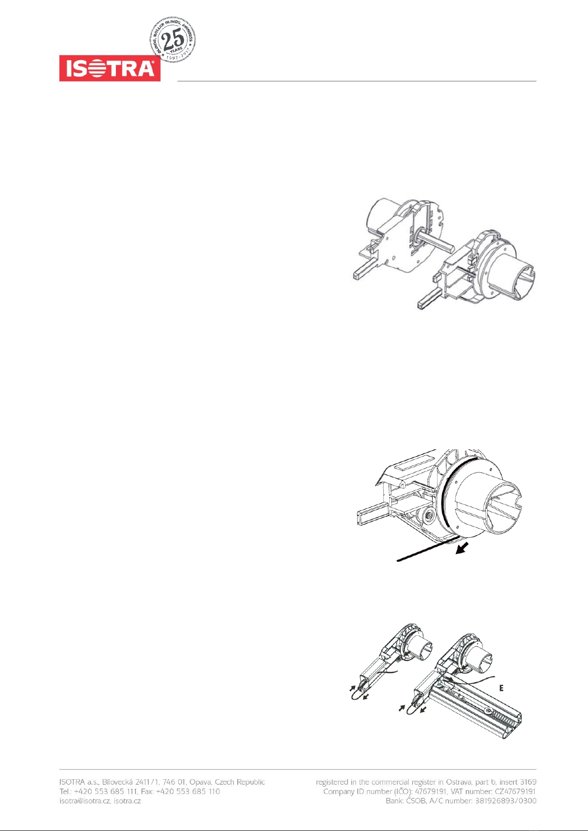
Make sure the marks are always at the same distance from
the centre of the end profile. Feed the cable round the pulley
(through the fork) and insert the cable through the hole in the
right-angled bracket on the end of the end profile. Feed the
cable back through the second hole and tighten
the cable clamps on the cable behind the right-angled bracket
so that the axle of the pulley is against
the marks in the end profile. (See fig.)
Check carefully the feed of the cable over all the pulleys both
on the front of the guide rail, as well as at
the end profile slider block and the cable feed pulley.
Pay attention to the symmetry of the spring.
4.17. INSERTING THE SPRING
The Veranda is still in its highest position. Check that the cable doesn’t cross over at the cable pulley, but running cleanly
side by side. Thread the spring into the forks of the pulleys and insert the cable into the cable unit. Make a knot in each
cable, behind the clamp unit. The Veranda is now under tension.
Remark concerning the motor:
If the motor is an Orea or an Altus RTS, please consult the enclosure of the concerned motor.
4.18. RUNNING THE MOTOR TO ITS STOPPING POINT
Let the motor run until it switches off.
Check that the motor stops where it should, not touching the end
pulley on the guide rail. The motor is not adjusted.
Both buttons on the motor are completely pushed down es-works (if
not push them down both). The motor will not stop by itself.
Let the Veranda run out until the cosen lower position is reached.
Then turn the switch for the test cable to its neutral position.
Next push the white or yellow button (depending on the built-in
side), so that the buttonlifts up. The lowest position is now adjusted.

MEASUREMENT AND ASSEMBLY MANUAL
Validity of the manual: 1. 3. 2018
6
4.19. CHECKING THE RIGHT ANGLES
The Veranda is now in its lowest position. Screw down the base
supports permanently. The guide rails and the box should stand
at right angles to each other. You can check this by using a large
try square or the 60-80-100 rule as shown in figure. A better,
and much more precise, way is to measure the diagonals of the
separate sections and of the entire construction. The difference
between these diagonals must not be more than 2 mm. Also
make sure that the guide rails run perfectly parallel along their
entire length, so that the tension between the extension profile and
the guide rails remains constant. (No hollow or bulge guide rails)
4.20. ADJUSTING THE HIGHEST POSITION
Roll up the Veranda, and stop it by using the fixed switch at ca 10
à15 cm before the Veranda closes. Check up that the end profile
runs straight.
Then push the blue button so that also this one lifts up. Let the
motor run a little downwards (10 à 15 cm). Then let the Veranda
close completely.
The motor will hum for another few seconds and finally it will stop
(to catch up possible future elasticity of the fabric). The final
switches for the motors are adjusted that way.
Should it be necessary to readjust the motor, then you can push down again both the buttons. The settings are then
erased and you can recommence the adjustments beginning at point 17.
4.21. SECURE THE VERANDA
Screw the socket-head screws on the square clamps for the lowest supports tightly. The entire system is now prevented
from sliding downwards.
4.22. POSITIONING THE PLASTIC U-PROFILE
Position the plastic U-section underneath the spring inside the end profile, so that the spring can move silently in the end
profile. Close the box, and the end profile. Mount the aluminium covers on to the end of the guide rails.
5. CONNECTION AND INSTALLATION OF THE MOTOR
Take the electric cable from the motor inside and connect the single-pole switch. If necessary, reverse the brown and black
leads following the signs on the switch.
For the installation of type 3 and 4 we proceed the same way, except in this case we have to use a relay box if we will be
running more than one motor from a single switch. For the connections, see flow chart R12. The installation of the sun
blind has to be done according to the rules.

MEASUREMENT AND ASSEMBLY MANUAL
Validity of the manual: 1. 3. 2018
7
5.1. FLOW CHART FOR A SINGLE-POLE SWITCH
There are 4 wires from the motor. Yellow-green (earth),
blue (neutral), brown and black (raise and lower).
From the fuse box, there are 3 wires. Yellow-green
(earth), blue (neutral), and phase. Connect the wires
as shown in the diagram. The phase wire from the fuse
box should be connected to terminal L. If necessary,
reverse the brown and black leads from the motor in the
switch so that the arrows on the switch
correspond to rolling up and unrolling the Veranda.
The 2 earth wires are connected using separate clamps.
Ditto for the 2 neutral wires.
5.2. WHY USE A RELAY BOX RI 2?
Sun blinds consisting of 3 or 4 panels are always driven by 2 motors.
These motors can be operated each using a separate switch. This allows
the panels to be opened separately in pairs. However, if you want to
operate the sun blind by using a single switch, it is necessary to use a
relay box. If this is not done, the system will oscillate, and the high
inductive and capacitive voltages created will permanently burn out the
built-in switches in the motor housing. Therefore, this good advice: always
use the relay box and switches we supply for single operation of 2 or more
motors. The same applies to a “wind/sun automat”.
žlutý/zelený
hnědý/černý
hnědý/černý
modrý

MEASUREMENT AND ASSEMBLY MANUAL
Validity of the manual: 1. 3. 2018
8
6. FAULT-FINDING
6.1. VERANDA WILL NOT UNROLL OR ROLL UP
The internal final switch points at zero in both directions. Push both adjusting buttons of the motor and continue adjusting
the final switch.
Wire making poor contact after extending motor cable. Check connections.
Motor has run hot. Leave ˝ hour to cool.
Faulty adjustment of the limit switches.
No current supplied to switch. Check using voltmeter.
Motor wrongly connected. Check using connection chart.
6.2. MOTOR HUMS
Check whether everything can freely turn in both directions. Is anything catching? (Cable?)
Capacitor in motor has blown (as a result of faulty connection of the motor).
Motor is wrongly connected: check correct connection of motor cables to the switch using the chart on p.7. A phase wire
(brown or black) has been transposed with neutral (blue). The motor will turn in one direction, but it will hum in the other.
6.3. MOTOR DOES NOT SWITCH OFF IN TIME
Faulty adjustment of limit switches.
6.4. INTERNAL FLAP NOT STRAIGHT
The guide rails are parallel, but not square to the casing Check by measuring diagonals.
6.5. INTERNAL FLAP SLIPS OUT OF THE GUIDES
The guide rails are a little too far apart. Adjust them slightly further together.
6.6. FABRIC STICKS DURING RAISING AND LOWERING
Internal flap not properly fitted in guide rail.
Steel cable not running properly over all pulleys.
Spring blocked.

MEASUREMENT AND ASSEMBLY MANUAL
Validity of the manual: 1. 3. 2018
9
6.7. FABRIC NOT TAUT AT BOTTOM
The guide rails are not straight with respect to the box.
Cable sticking somewhere.
Spring not under sufficient tension.
Faulty adjustment of limit switches.
End profile runs against the pulleys of the guide rails.
6.8. VERANDA IS NOT EVEN WHEN UNROLLED
Bad fitting of fabric rolls. Turn one of the tubes ¼ of ½ turn.
6.9. VERANDA IS NOT EVEN WHEN ROLLED UP
The two springs are not adjusted to proportional tension.
The spring for the panel which is rolled up the furthest must be adjusted a little tigher (or the other psring a little looser).
6.10. DIRECTION OF ROTATION OF THE MOTOR DOES NOT MATCH THE ARROWS
ON THE SWITCH
Reverse brown and black wires in the switch.
6.11. VERANDA ROLLS BACK UP WITHOUT STOPPING
Use a relay box (RI2).
6.12. ON A TYPE 3 OR 4: ONE MOTOR ROLLS UP WHILE THE OTHER ROLLS DOWN
Reverse the brown and black wires to one of the motors in the relay box.
6.13. AUTOMATIC OPERATION NOT WORKING WELL
See fitting instructions for wind/sun automatics.

MEASUREMENT AND ASSEMBLY MANUAL
Validity of the manual: 1. 3. 2018
10
7. METHOD FOR COUPLING 2 GUIDE RAILS
In some cases we have to couple 2 guide rails (when 2 or more systems are mounted beside one another).
This can be done in different ways.
7.1. MOUNTING THE BASE ATTACHMENT POINT IN THE MIDDLE
The coupling plate is fixed directly underneath both guide rails. The standard
attachment point is fixed on the coupling plate.
7.2. MOUNTING THE ATTACHMENT POINT HIGH PROFILE IN THE MIDDLE
The upper part of the high profile attachment point is replaced by the coupling plate. The coupling plate is fixed underneath
both guide rails.

MEASUREMENT AND ASSEMBLY MANUAL
Validity of the manual: 1. 3. 2018
11
7.3. MOUNTING THE ATTACHMENT POINT UNDERNEATH THE LEFT OR THE RIGHT
GUIDE RAIL
The coupling plate is fixed in front of or behind the used attachment point.
Other manuals for VERANDA HRV52
1
Other Isotra Accessories manuals