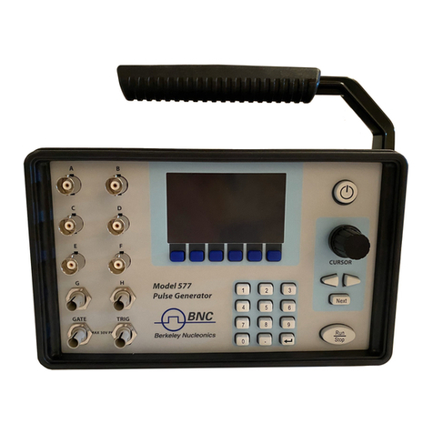
BNC 505-2C User manual

-~
ARTISAN
®
~I
TECHNOLOGY
GROUP
Your definitive source
for
quality
pre-owned
equipment.
Artisan Technology
Group
Full-service,
independent
repair
center
with
experienced
engineers
and
technicians
on staff.
We
buy
your
excess,
underutilized,
and
idle
equipment
along
with
credit
for
buybacks
and
trade-ins
.
Custom
engineering
so
your
equipment
works
exactly as
you
specify.
•
Critical
and
expedited
services
•
Leasing
/
Rentals/
Demos
• In
stock/
Ready-to-ship
•
!TAR-certified
secure
asset
solutions
Expert
team
ITrust
guarantee
I
100%
satisfaction
All
tr
ademarks,
br
a
nd
names, a
nd
br
a
nd
s a
pp
earing here
in
are
th
e property of
th
e
ir
r
es
pecti
ve
ow
ner
s.
Find the Berkeley Nucleonics 505-2C at our website: Click HERE

Berkeley Nucleonics Corporation
2955 Kerner Blvd.
San Rafael, CA 94901-5418
(415)453-9955 phone
(415)453-9956 fax
www.berkeleynucleonics.com
May 2005
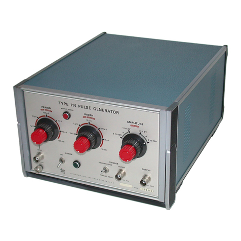
505 Pulse Generator
Operating Manual
Artisan Technology Group - Quality Instrumentation ... Guaranteed | (888) 88-SOURCE | www.artisantg.com
Contents
1 Introduction................................................................1
Technical Support..............................................................................................2
Warranty.............................................................................................................2
Package Contents ..............................................................................................2
Safety Issues.......................................................................................................3
2 Front Panel Overview...............................................5
505 Front Panels ...............................................................................................6
Display Layout and Indicators ......................................................................................................6
Keypads ..............................................................................................................................................6
3 Pulse Concepts & Pulse Generator Operation ......9
Counter Architecture Overview ..................................................................................................10
System Timer Functions...............................................................................................................10
Channel Timer Functions ............................................................................................................11
Dependent & Independent Timing Events...............................................................................11
Selecting Menus..............................................................................................................................11
Numeric Input Mode......................................................................................................................12
Entering Numeric Parameters....................................................................................................12
Selecting Menu Parameters...........................................................................12
Enable/Disable Pulse Output.......................................................................................................12
Setting Pulse Sync Source............................................................................................................12
Setting Pulse Gate Control ............................................................................12
Configuration # ...............................................................................................................................13
Storing a Configuration ................................................................................................................13
Recalling System Configurations ...............................................................................................13
Setting System Mode of Operation .............................................................................................13
Enabling External Gate Control.................................................................................................13
Power On Configuration ...............................................................................................................14
Setting Auto Start Mode ...............................................................................................................14
Setting System Serial Port Baud Rate ......................................................................................14
Setting Communication GPIB Address.....................................................................................14
Setting Communication Echo Mode...........................................................................................14
Setting Key Repeat Rate...............................................................................................................14
Setting Key and Knob Volume ....................................................................................................14
Setting Pulse Timing Parameters ..............................................................................................15
Setting Pulse Output Parameters...............................................................................................15
Setting Pulse Mode of Operation.................................................................................................15
Delaying the Start of Channel Output ......................................................................................15
Rearming the Channel Timers....................................................................................................15
Artisan Technology Group - Quality Instrumentation ... Guaranteed | (888) 88-SOURCE | www.artisantg.com
Setting Pulse Gate Control ..........................................................................................................16
Setting the System Internal Rate Generator ..........................................................................16
Setting System Mode of Operation ............................................................................................16
Enabling System Trigger or Gate...............................................................................................16
Power On Configuration...............................................................................................................16
Setting Auto Start Mode...............................................................................................................16
4 505 Menus..................................................................17
505 Menu Structure ........................................................................................18
CHANNEL Menu...........................................................................................................................18
MODE Menu....................................................................................................................................18
TRIG/GATE Menu .........................................................................................................................18
SYSTEM Menu ...............................................................................................................................19
SETUP Menu ..................................................................................................................................19
5 Operating the 505 ....................................................21
Quick Start - Normal Internal Rate Generator Operation........................22
Quick Start - Normal External Trigger Operation......................................22
System Timer Overview..................................................................................23
To Use Continuous Mode..............................................................................................................23
To Use Single Shot Mode ..............................................................................................................23
To Use Burst Mode.........................................................................................................................23
To Use Duty Cycle Mode...............................................................................................................24
Channel Timer Overview ...............................................................................24
To Use Normal Mode Function....................................................................................................24
To Use Channel Single Shot Function ......................................................................................24
To Use Channel Burst Mode Function ......................................................................................25
To Use Channel Duty Cycle Function .......................................................................................25
To Use the Channel Gating Function........................................................................................25
External Input Overview................................................................................25
To Generate a Pulse on Every Trigger Input..............................................26
To Generate a Burst of Pulses on Every Trigger Input.............................26
To Start a Continuous Stream of Pulses Using the External Trigger.....26
To use the External Gate to Control the System........................................27
6 Programming the 505..............................................29
Talking to the Pulse Generator.....................................................................30
RS232 Interface Overview..............................................................................30
GPIB Interface Overview ...............................................................................30
Programming Command Types and Format...............................................31
IEEE 448.2 Common Command Format.....................................................31
SCPI Command Keywords.............................................................................31
SCPI Command Format.................................................................................31
Artisan Technology Group - Quality Instrumentation ... Guaranteed | (888) 88-SOURCE | www.artisantg.com
SCPI Query Format.......................................................................................................................31
SCPI Keyword Separator ...............................................................................32
SCPI Optional Keywords................................................................................32
SCPI Specific and Implied Channel .............................................................32
SCPI Parameter Types ...................................................................................32
Error Codes.......................................................................................................33
Programming Examples .................................................................................33
505 SCPI Command Summary .....................................................................34
505 SCPI Command Summary .....................................................................35
505 SCPI Command Summary .....................................................................36
505 SCPI Command Summary .....................................................................37
IEEE 488.2 Common Commands .................................................................38
Appendix ......................................................................39
Appendix A - Specifications ......................................40
505 Specifications ............................................................................................40
Artisan Technology Group - Quality Instrumentation ... Guaranteed | (888) 88-SOURCE | www.artisantg.com
1
1
Introduction
Artisan Technology Group - Quality Instrumentation ... Guaranteed | (888) 88-SOURCE | www.artisantg.com
2
Introduction
Thismanualis a reference designedtofamiliarizeyou with the BerkeleyNucle-
onics505pulsegenerator and is arrangedsothatyoucan easily find the infor-
mationyou’relooking for. Generally,eachtopic has itsownsection, and no
sectionassumesthatyou’vereadanythingelseinthemanual.
Technical Support
Forquestionsorcomments about operating the 505--our technicalstaffcanbe
reachedviaone of thefollowingmethods:
- Phone - (415)453-9955
- Fax - (415)453-9956
-Internet-www.berkeleynucleonics.com
Warranty
Inadditiontoa 30-day money backguarantee,the505has a one-year limited
warrantyfromthe dateofdelivery. Thiswarranty covers defectsin materialsand
workmanship. BerkeleyNucleonicswill repair orreplaceanydefective unit.
Contactusfor informationonobtaining warrantyservice.
Package Contents
Thebox youreceiveshould containthefollowing:
-505PulseGenerator
- AC Power Cord
-User’s Manual
ContactBerkeleyNucleonics(415-453-9955) if any partsaremissing.
Artisan Technology Group - Quality Instrumentation ... Guaranteed | (888) 88-SOURCE | www.artisantg.com
3
Safety Issues
Normaluseof test equipment presentsacertainamount of dangerfromelectri-
calshockbecausetestingmust be performed where exposedvoltageis
present.
Anelectricalshock causing 10milliampsofcurrent to passthroughtheheart will
stop most human heartbeats. Voltage as low as 35 VDC or RMSAC should be
considereddangerousand hazardous sinceitcan produce alethalcurrentunder
certainconditions. Highervoltages pose an evengreaterthreatbecause such
voltagecan easily producealethalcurrent. Yournormalworkhabitsshould
includeallaccepted practicesthatwillprevent contactwithexposedhigh volt-
age,andsteer current away fromyourheartin case ofaccidentalcontactwith a
highvoltage. Youwill significantly reducetheriskfactor ifyouknowand observe
thefollowing safetyprecautions:
• Ifpossible,familiarize yourself withtheequipment being testedandthe
locationofitshigh-voltagepoints. However,rememberthathighvoltagemay
appearatunexpected points in defectiveequipment.
• Donotexpose highvoltageneedlessly. Remove housingandcovers only
whennecessary. Turnoffequipmentwhile makingtestconnections inhigh-
voltagecircuits. Dischargehigh-voltage capacitors aftershuttingdown
power.
• WhentestingACpoweredequipment, remember that AC linevoltageis
usuallypresenton powerinputcircuits,such astheon-off switch,fuses,
powertransformeretc.
• Useaninsulatedfloor material oralarge,insulatedfloor mat tostandon,and
aninsulatedwork surface onwhichtoplace equipment. Make certainsuch
surfacesarenotdamp or wet.
• Usethetime-proven “onehandin thepocket”technique whilehandlingan
instrumentprobe. Beparticularly carefultoavoidcontact with metalobjects
thatcouldprovide agoodgroundreturn path.
• Neverworkalone. Someone should always benearbytorenderaid if neces-
sary. TraininginCPRfirstaid is highly recommended.
Artisan Technology Group - Quality Instrumentation ... Guaranteed | (888) 88-SOURCE | www.artisantg.com
4
Artisan Technology Group - Quality Instrumentation ... Guaranteed | (888) 88-SOURCE | www.artisantg.com
5
2
Front Panel Overview
Artisan Technology Group - Quality Instrumentation ... Guaranteed | (888) 88-SOURCE | www.artisantg.com
6
Front Panel Overview
BNC 505 Front Panels
Display Layout and Indicators
A2 line x 16 character, backlit LCD display module displays all system param-
etersandstatus information. The statusinformationis located intheupper-right
cornerofthe display. There aretwoenunciators:
• Rotating Pie Indicatestheunit isactivelygenerating pulses,or
armed andwaitingforan external trigger.
• VerticalArrow Indicatesthefunction keyhasbeen pressed.
Theupper-leftside ofthedisplay contains thetitleof thecurrentmenu. The
centertopline containsthetitle of thecurrentparameter. The bottomlinedis-
playsthe valueofthe currentparameter.
• PowerSwitch Thepowerswitch is locatedonthelower-right corner of
thefront panel.Pushoncetoturn theuniton;push
againto turntheunit off.
Keypads
Thekeypadprovidesaccess to the variousmenusandeasyediting of the
parametersneededtocontroltheinstrument.
• FunctionKey Thesystemparameters areorganizedinmenus which
areaccessedby pressing theFUNCTIONkey and then
theappropriatefunction (yellowlabels). Alltheparam-
etersforone channel aregroupedtogetherin the
CHANNELmenu. Toaccessadditionalchannels,
presstheFUNCTIONkeyandthen theCHANNELkey
(whileinthe CHANNELmenu)and themenuwill incre-
mentthe channelnumber. The contentsof eachofthe
menusisdiscussedindetail in section 4 of this manual.
• NextKey TheNEXTkeyprovidesaccess to all the parametersin
amenu. Pressingthe NEXT key selectsthenextpa-
rameterin thecurrentlydisplayedmenu.
• ArrowKeys Theup/downarrows areusedto increment/decrement
thecurrentparameter. For numeric parametersthe
blinkingcursorindicateswhichdigit will be
incremented. Theright/leftarrows areusedtochange
theselecteddigitfor numeric parameters.
Artisan Technology Group - Quality Instrumentation ... Guaranteed | (888) 88-SOURCE | www.artisantg.com
7
• RotaryKnob The Rotary Knobmaybeused toadjustthecurrent pa-
rameterasan alternate totheARROWkeypad. The
stepsizeiscontrolled by the positionofthecursor.
However,turningtheknobfaster willincreasethe step
size. Pushingtheknob performs thesamefunctionas
pushingtheNEXTkey,selecting the nextparameterin
thecurrentlydisplayedmenu.
• ChannelOutputs Thepulsegenerator output isavailablefromBNC con-
nectorsonthe frontpanel. Theoutput isadjustable
from 2V to 20V into a high impedance load. The drive
impedance is 50 ohm, so if the load is 50 ohm the out-
putvoltagewill be one-halfoftheset voltage. Eight
channelunitsshare power suppliesbetweenpairsof
channels. Four pair of channels, 1 & 5, 2 & 6, 3 & 7,
and4&8share the same voltagesupply.
• ExternalInput Theexternalinput providesatriggerand/or gatefunc-
tionforboth thesystemtimer andthechanneltimers.
Artisan Technology Group - Quality Instrumentation ... Guaranteed | (888) 88-SOURCE | www.artisantg.com
8
Artisan Technology Group - Quality Instrumentation ... Guaranteed | (888) 88-SOURCE | www.artisantg.com
9
3
Pulse Concepts and
Pulse Generator Operations
Artisan Technology Group - Quality Instrumentation ... Guaranteed | (888) 88-SOURCE | www.artisantg.com
10
Pulse Concepts and
Pulse Generator Operation
Counter Architecture Overview
System Timer Functions
TheSystemTimerfunctions asanon-retriggerable, multi-vibratorpulsegenera-
tor. Thismeans thatoncestarted,depending onthemode,thetimer will pro-
ducepulsescontinuously. Before pulses willbegenerated,the timer mustbe
armedandthenreceive a start pulse.Armingthecounter is done bypressing
theRUNkey. With external triggerdisabled,theRUN key alsogeneratesthe
startcommand forthecounter. With externaltriggerenabled, theexternaltrigger
providesthestart pulse. In eithercase,oncestarted,the counter operationis
determinedbytheSystem Mode Generator. Standardmodesinclude:
•Continuous Oncestarted,Topulsesaregeneratedcontinuously.
•SingleShot OneTopulse isgeneratedforeach startcommand.
•BurstMode 'n'Topulsesaregeneratedfor each startcommand.
•DutyCycle Once started,Topulsescycleonandoffcontinuously.
TheTopulses are distributedtoall of thestartinputsof the ChannelTimersand
ModeGenerators.
Output
Pulses
Output
MUX
Internal
To Pulse
External
Input
Arm
Start
*Gate To
Internal System Timer
and System Mode
Generator
Channel Timersand Channel
Mode Generators
*Start source is: RUN button inInternal Modes
External inputinExternaltrigger modes
** Channels arearmed bythe RUN button. In singleshotandburst modes
channells maybe rearmedbypressing the RUNasecondtime.
RUN
Command
**
Start
Gate
Arm
* Start source is: RUN button in Internal Modes
External input in External trigger modes.
** Channels are armed by the RUN button. In single shot
and burst modes channels may be rearmed by pressing the
RUN button a second time.
Artisan Technology Group - Quality Instrumentation ... Guaranteed | (888) 88-SOURCE | www.artisantg.com
11
Channel Timer Functions
TheChannelTimerfunctions asanon-retriggerable, delayed,oneshotpulse
generator. Thismeansthatthetimer willonlygenerateone delayed pulsefor
everystartpulse received. Oncethechanneltimer hasstartedcounting,addi-
tionalstartpulses will beignoreduntilthe pulsehasbeencompleted (non-
retriggerable). Thestartpulseforeachchannel is providedbythe internalTo
pulsegeneratedby theInternalSystemTimer. Whether or notapulse is gener-
atedforeachTopulseisdeterminedby the Channel ModeGenerator. Standard
modesinclude:
•Normal Apulseisgeneratedfor eachTopulse.
•SingleShot Onepulse is generatedatthefirstTopulse,afterwhich
outputisinhibited.
•Burst Apulseisgeneratedfor eachTopulse,'n'times,after
whichoutputis inhibited.
•DutyCycle Apulse isgeneratedforeachTopulse “n” times,after
whichtheoutputisinhibited for ‘m’ times. The cycle is
thenrepeated.
Differentmodesmaybe selected for eachoutput,allowinga wide variety of
outputcombinations. Eachoutput may also beindependentlydisabledor gated
(usingthe externaltriggerinput).
Dependent & Independent Timing Events
The505allows theuserto controltherelationshipbetween theChannelTimers
bysettingthe syncsourceforeach timer. Independenteventsareall timed
relativetothe internalTostartpulse. Dependenteventsmaybelinkedtogether
bysettingthesyncsource tothecontrolling event. Thisallowsthe instrumentto
matchthetimed eventsandadjustments can bemadein oneeventwithout
detuningthetiming betweenitanda dependentevent.
Selecting Menus
Parametersaregrouped in menus,selectableusing theyellowmenukeys. To
selectthechannel parameterspress theFUNCTIONkeyand theCHANNELkey.
Repeatthisprocess until the desiredchannelappears. Toselectother menus
presstheFUNCTION keyandthenthe keycorrespondingto thedesiredfunc-
tion.
Artisan Technology Group - Quality Instrumentation ... Guaranteed | (888) 88-SOURCE | www.artisantg.com
12
Numeric Input Mode
Whenthe currentitemis numeric,thesystem enterstheNumericInputMode. In
thismodedatamaybeedited in one of two ways. Using the arrowkeypad,the
Left and Right arrow keys are used to select a digit to edit. The selected digit
blinkstoidentifyitself as the active digit. TheUpandDownarrowkeys are then
usedtoincrementor decrement thisdigit. Alternately,afterusing theLeftand
Rightarrowkeysto select an activedigit,theadjustment knob may beusedto
incrementanddecrement this digit. Theadjustmentknobfeaturesspeed de-
pendentresolution. Slowrotation will incrementordecrementthe active digitby
one. As you increase the speed of rotation, the parameter will be 10 to 1000
timesfasterdependingonthe speed.
Entering Numeric Parameters
Whenthecurrent itemisnon-numeric,the Up andDownarrow keys areusedto
selectamongdifferentoptionsforthe parameter. Theadjustment knobmayalso
beusedtochange the selection. If theitemisan on-off toggle, theUparrow
(CWadjustementknob) enables theitemandthe Downarrow(CCWadjustment
knob)disablestheitem.
Selecting Menu Parameters
Menusincludeall the parametersforsetting up thepulsegenerator. To selecta
parameter, withinthecurrent menu, presstheNEXTkey. Pressingtherotary
adjustmentknobis equivalent topressingtheNEXT key andwillalsoselect the
nextparameter.
Enable/Disable Pulse Output
WithintheCHANNELmenu page toenableordisablethe output ofanindividual
timer:
• Channel Enablesordisables thepulseoutputfor thecurrent
channel.
Setting Pulse Sync Source
WithintheCHANNEL menu tosetthestarting point forthepulsedelay param-
eter:
• Sync Setthesync sourceforthe channel,whichmay beToor
anyof theotherchannels. The unitwillnotallowa chan-
neltotrigger itself.
Setting Pulse Gate Control
• Gate Enables/disablesthechannel gatingusingthe external
triggerinput. Thisfunction isindependentofany other
useofthetrigger input. Care should betakentoensure
thatallusesofthe trigger are compatible. To enable
thegate,setthe gate to active loworactivehigh.
Artisan Technology Group - Quality Instrumentation ... Guaranteed | (888) 88-SOURCE | www.artisantg.com
13
Configuration #
Theconfiguration# specifies thelocationto store thecurrentsystemconfigura-
tion. Numbersrangefrom1 to n,where"n"is the number ofstoredconfigura-
tions.
*NOTE: The number of storage locations is model dependent; see the specifi-
cations for your model. You cannot store to the zero location, as that contains
the factory default values.
• FromtheStore menu,pressthe setupbutton(function +setup).
Storing a Configuration
Usethefollowing procedure tostoreacomplete systemconfiguration:
• Setallparametersto the desired value.
• Selectaconfiguration number.
Recalling System Configurations
Usethefollowing procedure torecallastored ordefaultsystemconfiguration:
• Selectaconfiguration number.
• FromtheRecallMenu,press therecallbutton (function+recall).
*Note: Configuration 0 is the factory default setting.
Period 0.001s (1kHz)
Mode Continuous
Trigger Disabled
Pulsewidth 0.0002
Delay 0.0
Mode Normal
Setting System Mode of Operation
• MODE SelectstheTomode:Continuous,Single Shot,Burstor
DutyCyclemode.
• #/BURST Setsthenumber of pulses tobegeneratedwhen in the
Burstmode.
• DC ON Setsthenumberof pulsesto begeneratedforeach
“ON”cycle.
• DC OFF Setsthenumberof pulses to skip for each“OFF”cycle
whenin theDutyCycle mode.
*NOTE: Any mode may be started by either the RUN key in the internal
trigger mode or armed by the RUN key and started by an external trigger in
the external trigger mode. In the single shot and burst modes, (internally
triggered) the unit disarms itself at the end of the pulse train. Pressing the
RUN key after the unit has been disarmed will generate a new pulse train.
Artisan Technology Group - Quality Instrumentation ... Guaranteed | (888) 88-SOURCE | www.artisantg.com

14
Enabling External Gate Control
• EXTin Selectsexternal inputusageforcontrollingTo: dis-
abled, edge triggered or level gated.
*NOTE: When the gate disables the System Timer, the timer is reset. The
gate edge, to enable the timer, will restart the System Timer, which synchro-
nizes the Topulse to the gate and minimizes jitter relative to the gate. The
trigger threshold applies to all uses, channel and system, of the trigger/gate
input.
Power On Configuration
Uponpower-upthe unitwillloadthe lastconfigurationstoredor recalled. Ifthe
Autostartmodeis enabled, the unitwillbegingenerating pulses afterloadingthe
latestconfiguration.
Setting Auto Start Mode
• Auto Autorun startupfunction-allowsunit toautomatically
generatepulsesafter startup iscomplete.
Setting System Serial Port Baud Rate
• BaudRate Selectsthebaud rate(withinthe SYSTEMmenu)for
theRS232interface.
*NOTE: The unit will not respond to computer commands unless the appropri-
ate BAUD rate or GPIB address is selected.
Setting Communication GPIB Address
• GPIBAddress SelectstheGPIB Address(withinthe SYSTEMmenu).
Setting Communication Echo Mode
• Comm Echo Selects whetherto echo charactersback tothe host
computerornot.
Setting Key Repeat Rate
• KeyRate Setstherate at whichthekeys will repeatwhenheld
down.ThisismostusefulwhenusingtheUp/Downar-
rowstochange parameters.
*NOTE: The key repeat rate is fairly accurate (better than one millisecond)
and may be used to increase/decrease a parameter at a set rate.
Artisan Technology Group - Quality Instrumentation ... Guaranteed | (888) 88-SOURCE | www.artisantg.com

15
Setting Key and Knob Volume
• KeyVolume Setsthekey clickvolume.
• KnobVolume Sets the parameteradjustmentknob clickvolume.
Setting Pulse Timing Parameters
WithintheCHANNEL menu,setthedelay untilthestartof apulseandthe
pulsewidth:
• Delay Setsthedelay from thesyncsourceto thestartofthe
pulse.
• Width Setsthewidth of theactiveportionof the pulse.
Setting Pulse Output Parameters
WithintheCHANNEL menu,setthepulse polarityandthepulse amplitude
(whether thepulseis active highoractive low):
• Polarity Setsthepulse polarity either activehighoractive low
usingthearrow keysortherotary knob.
• Amplitude Setsthepulseamplitude, 2 to 20 voltswithahighim-
pedanceload.
Setting Pulse Mode of Operation
Eachchannelmay be setindependentlytooperate inoneoffour modes: normal,
singleshot, burst,orduty cycle(withinthe CHANNELmenu):
• Mode Selectsthemode forthecurrentchannel. Additional
parametersareprovidedfor the burst mode andthe
dutycycle mode.
• #/Burst Setsthenumber of pulses intheburstmode to gener-
atebeforeinhibiting output.
• OnCycle Setsthenumberof pulses togeneratebeforeinhibiting
output.
• OffCycle Setsthenumberof pulses to inhibitbeforerepeating
theOnCycle.
Delaying the Start of Channel Output
Withinanychannelmode,the outputofthe channelcanbe delayedusingthe
waitparameter(within theCHANNELmenu):
• Wait Setsthe numberofTopulses towaituntilenabling the
channeloutput.
Rearming the Channel Timers
Inthesingle shot modeandtheburst modetheChannelTimersmayberearmed
aftercompletingthe pulsetrainbypushing theRUNkey again.
Artisan Technology Group - Quality Instrumentation ... Guaranteed | (888) 88-SOURCE | www.artisantg.com
This manual suits for next models
1
Table of contents
Other BNC Pulse Generator manuals
Popular Pulse Generator manuals by other brands

Schwarzbeck
Schwarzbeck IGUU 2916 instruction manual

HP
HP 33120A user guide

Delta Electronics
Delta Electronics Pulse Generator Card PG-05 instruction sheet

Honeywell
Honeywell IN-S Series instruction manual

Delta Electronics
Delta Electronics Pulse Generator Card PG-03 Installation instruction

GENII
GENII SLEEP user manual