Deif AL8-2 Owner's manual

DEIF A/
S
DEIF A/S Tel: (+45) 9614 9614
Frisenborgvej 33, DK-7800 Skive Fax: (+45) 9614 9615
Denmark E-mail: deif@deif.com
Programming manual
Alarm panel AL8-2
4189320003D
•
Compact Q96 design
•
Extremely easy push-button programming (no jumpers
or the like)
•
Individual programming of each input:
N/O or N/C, time delay, alarm inhibit, output
and cable supervision
•
Up to 5 units in master/slave configuration
•
Clear identification of first alarm received in case of
successive alarms

AL8-2 – Programming manual
4189320003D
Page 2/19
CONTENTS:
BEFORE YOU START PROGRAMMING ....................................................................3
THE PRINCIPLE OF PROGRAMMING........................................................................6
WHICH FUNCTIONS MAY BE PROGRAMMED? .......................................................7
HOW TO PROGRAMME INDIVIDUAL FUNCTIONS (INPUTS 1 TO 8).......................8
ALARM ON OPEN OR CLOSED SIGNAL CONTACT (N/C, N/O) .............................9
SELECTION OF OUTPUT RELAY (OUTPUT(S) AAND/OR OUTPUT B) .............. 10
INHIBIT OF INCOMING ALARM (INHIBIT) ............................................................. 10
ALARM ON CABLE FAILURE (CABLE FAILURE) .................................................. 11
TIME DELAYED REGISTRATION OF AN ALARM CONDITION (DELAY OF
ALARM) ..................................................................................................................11
SELECTION OF REQUESTED TIME DELAY (SET TIME) .....................................12
SELECTION OF BASIC TIME:..........................................................................13
SELECTION OF ADDITIONAL TIME:...............................................................14
PROGRAMMING OF COMMON FUNCTIONS ..........................................................15
SELECTION OF ACTIVATION/DEACTIVATION OF OUTPUT RELAY AON AN
ALARM CONDITION (N/O, N/C)............................................................................. 15
SELECTION OF TIME LIMITED ACTIVATION/DEACTIVATION OF OUTPUT
RELAY A................................................................................................................. 16
SELECTION OF ACTIVATION/DEACTIVATION OF OUTPUT RELAY BON AN
ALARM CONDITION (N/O, N/C)............................................................................. 17
SELECTION OF TIME LIMITED ACTIVATION/DEACTIVATION OF OUTPUT
RELAY B................................................................................................................. 17
DELAYED CANCELLATION OF INHIBIT FUNCTION (0..40 SECS).........................18
"MASTER"/"SLAVE" CONFIGURATION..................................................................19

AL8-2 – Programming manual
4189320003D
Page 3/19
On delivery, the AL8-2 alarm panel is programmed to the following functions:
Individual functions
•Alarm on closed signal contact (N/O)
•No activation of output relays A and B on an alarm condition
•Inhibit function NOT activated
•No alarm on cable failure
•Immediate registration of an alarm condition (i.e. time delay 0 sec.)
Common functions
•Output relays A and B activated on an alarm condition (N/O)
•Duration of activation is unlimited (i.e. time limit 0 sec.)
•No delay of cancellation of inhibit function (i.e. time delay 0 sec.)
BEFORE YOU START PROGRAMMING
Programming the DEIF alarm panel AL8-2 requires only few and simple preparations:
Firstly, auxiliary voltage should be connected (indicated by green light in the LED
marked "POWER ON").
CONNECTIONS

AL8-2 – Programming manual
4189320003D
Page 4/19
Secondly, the bezel and front sheet are removed to give access to the programming
front plate.
The descriptive text for alarm channels 1-8 and the output channels A and B is
written/set on the shown text label.
We recommend using "letter-press" to set the text (height: 2.7mm) or typing the text on
the label.
Please note that the horizontal lines at both sides of the label indicate lines to be
written on. Do not write between the lines.

AL8-2 – Programming manual
4189320003D
Page 5/19
ABC123
ABC123 ABC123
ABC123
CORRECT WRONG
The horizontal line at the top of the label indicates the left margin.
The text label is mounted behind the front sheet which has an adhesive rear. Label and
front sheet are easily separated and put together again, though.
NOTE: For marine applications, the front sheet is always to be glued in order to
prevent unauthorised personnel from changing the settings subsequently.
The arrows at the right side of the label indicate the connection of the individual alarm
channel to output relay(s) A and/or B, if any – see the arrows on the front sheet. Not
applicable arrows can be deleted using black ink.
NOTE: The LED indicating "POWER ON" according to the text on the front sheet
is the same LED which, on the programming front plate, is designated "DELAY
OF ALARM". The LED will of course continue being lit even though the front
sheet and the bezel are removed, provided that auxiliary voltage is connected
and the unit is in operation.

AL8-2 – Programming manual
4189320003D
Page 6/19
THE PRINCIPLE OF PROGRAMMING
Programming of the alarm panel is carried out by means of the 3 push-buttons
CHANNEL SELECT, FUNCTION SELECT and ENTER, positioned at the lower right
corner of the front plate.
The principle of programming is as follows:
"Point" to the requested channel (by means of CHANNEL SELECT); then "point" to the
requested function (by means of FUNCTION SELECT); finally select, i.e. enter, the
requested function (by means of ENTER).
The LEDs will, as described in the following,
indicate which channel/function is being
programmed at the moment. The
channels/functions are shown in a certain
order. The CHANNEL SELECTOR first points
to channel 1, repeated pressing of the push-
button enables stepping through the channels
1-2-3-4-5-6-7-8-1-2-3, etc. Likewise you step
through the various functions. The order of
these appears from the following pages of this
manual.

AL8-2 – Programming manual
4189320003D
Page 7/19
WHICH FUNCTIONS MAY BE PROGRAMMED?
It is possible to program 5 functions for each of the input channels 1 to 8.
Furthermore, programming of 4 common functions is possible.
The individual functions are as follows:
1) Registration of alarm on open or closed signal contact
- i.e. selection between N/C or N/O.
2) Activation of output(s) A and/or B on an alarm condition
- "OUTPUT A", "OUTPUT B"
3) Inhibit of incoming alarms
- "INHIBIT"
4) Detection and indication of cable failure
- "CABLE FAILURE"
5) Time delayed registration of an alarm condition.
The time delay "DELAY OF ALARM" can be set within the range 0..40 secs at intervals of 1
sec.
The common functions are as follows:
1) Activation/deactivation of relay for output A on an alarm condition
- (N/O, N/C)
2) Time limited activation/deactivation of output A.
The time limit can be set within the range 1..10 secs at intervals of 1 sec.
3) Activation/deactivation of relay for output B on an alarm condition
- (N/O, N/C)
4) Time limited activation/deactivation of output B.
The time limit can be set within the range 1..10 secs at intervals of 1 sec.
5) Delayed cancellation of inhibit function.
The delay can be set within the range 0..40 secs at intervals of 1 sec.
NOTE: When common functions are programmed, no channel is selected, only
functions. Individual functions may be programmed before common
functions or vice versa. The description of the programming of common
functions starts on page 15.

AL8-2 – Programming manual
4189320003D
Page 8/19
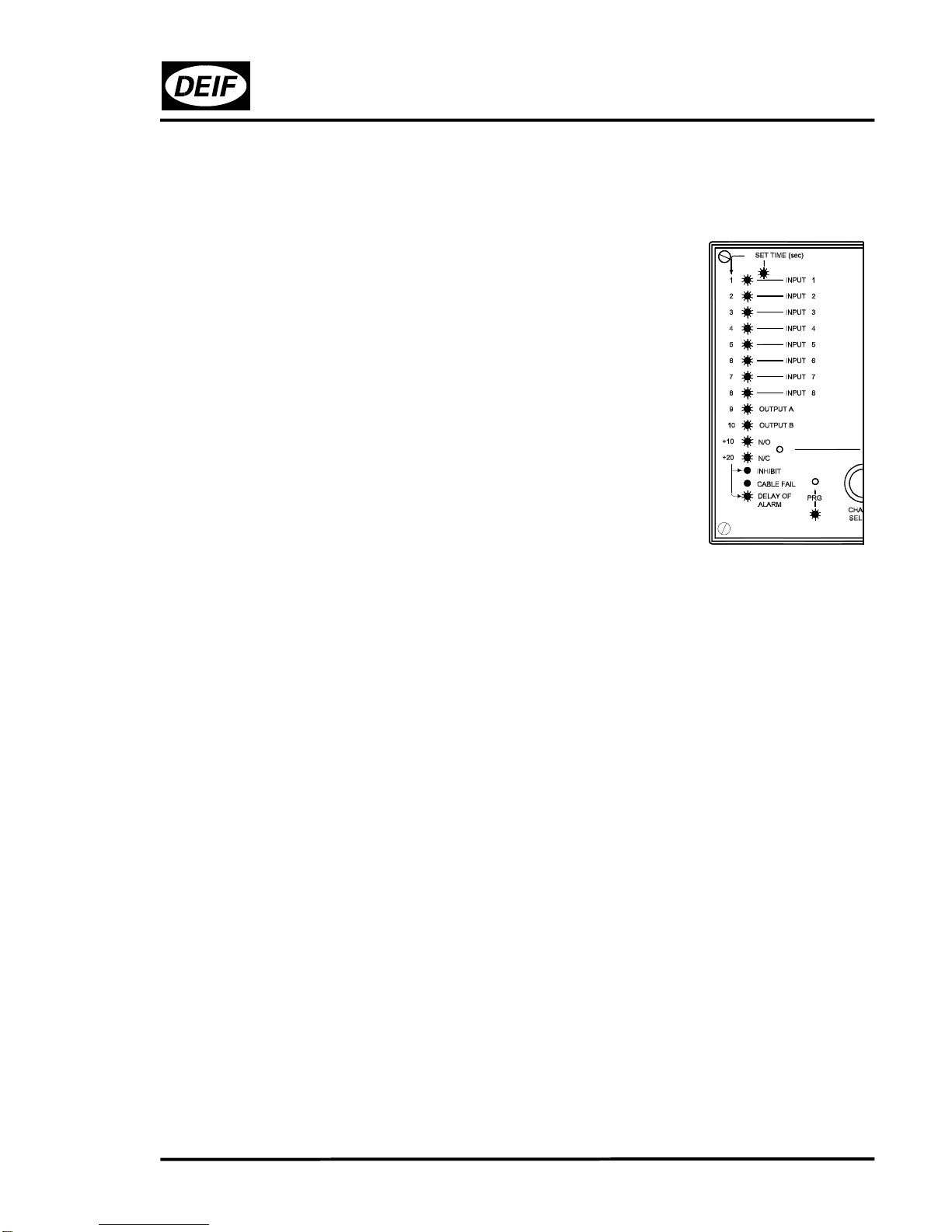
HOW TO PROGRAMME INDIVIDUAL FUNCTIONS (INPUTS 1 TO 8)
Set AL8-2 to programming status:
Press the PRG button. This button is slightly countersunk when
compared with the front plate, and a thin, sharp tool like e.g. a small
screwdriver, a needle or the like must be applied to press this button.
Do not use a pencil. The lead may break and fall behind the front plate.
After having pressed the PRG push-button, the LED below the push-
button will be lit (green), indicating that the alarm panel has been set to
the programming status and that programming may be started.
The LED for "DELAY OF ALARM" (i.e. "POWER ON") is switched off
when the unit is set to programming status.
The moment the "PRG" LED is lit (green), the LED for input channel 1 (INPUT 1)
is lit (green) to indicate that this channel may now be programmed.
When pressing the channel selector CHANNEL SELECT, the LED for channel 1 (INPUT
1) is switched off and the LED for channel 2 (INPUT 2) is lit (green), etc.
First step of the programming is thus to select input channel. When the requested input
channel is indicated, i.e. the relevant LED is lit (green), the FUNCTION SELECT push-
button is pressed.
NOTE: The LED for the selected input channel will continue being lit (green)
throughout the complete programming procedure for the relevant channel.
FUNCTION SELECT points to the individually programmable functions in the following
order:
1: N/O, N/C
2: OUTPUT A, OUTPUT B
3: INHIBIT
4: CABLE FAILURE
5: DELAY OF ALARM
I.e., after the first push of FUNCTION SELECT, N/O, N/C is selected.

AL8-2 – Programming manual
4189320003D
Page 9/19
ALARM ON OPEN OR CLOSED SIGNAL CONTACT (N/C, N/O)
The "N/O" and "N/C" LEDs indicate the actual function as follows:
NOTE: Both LEDs are lit simultaneously.
EITHER: GREEN N/O FUNCTION:
RED N/C Alarm on closed signal contact
OR: RED N/O FUNCTION:
GREEN N/C Alarm on open signal contact
By pressing the FUNCTION SELECT push-button, the LEDs switch from one indication
to the other – thus changing the function.
When the indication of the LEDs shows the requested function, this is entered into the
programme memory by pressing the ENTER push-button.
Pressing ENTER results in the next function in the order being automatically pointed to:
selection of output relay.

AL8-2 – Programming manual
4189320003D
Page 10/19
SELECTION OF OUTPUT RELAY (OUTPUT(S) A AND/OR OUTPUT B)
The LEDs for "OUTPUT A", "OUTPUT B" indicate the actual function as follows:
NOTE: Both LEDs are lit simultaneously.
EITHER: RED OUTPUT A FUNCTION:
RED OUTPUT B No output relays are
activated on alarm
OR: GREEN OUTPUT A FUNCTION:
RED OUTPUT B Output relay A is activated
on alarm
OR: RED OUTPUT A FUNCTION:
GREEN OUTPUT B Output relay B is activated
on alarm
OR: GREEN OUTPUT A FUNCTION:
GREEN OUTPUT B Both output relays A and B
are activated on alarm
Pressing the FUNCTION SELECT push-button will cause a change from the actual LED
indication/function to the next in the order, and so the FUNCTION SELECT push-button
is pressed, till the requested function is indicated by the LEDs. The requested function is
entered into the programme memory by pressing the ENTER push-button.
Pressing ENTER results in the next function in the order being automatically pointed to:
Inhibit function.
INHIBIT OF INCOMING ALARM (INHIBIT)
The "INHIBIT" LED indicates the actual function as follows:
EITHER: RED INHIBIT FUNCTION:
Inhibit function is NOT
active for this input
channel
OR: GREEN INHIBIT FUNCTION:
Inhibit function is active for
this input channel
Pressing FUNCTION SELECT causes a change from one
function to the other. When the required function is indicated,
enter this into the programme memory by pressing ENTER.
Pressing ENTER results in the next function in the order being
automatically pointed to: Alarm on cable failure.

AL8-2 – Programming manual
4189320003D
Page 11/19
ALARM ON CABLE FAILURE (CABLE FAILURE)
The LED for "CABLE FAILURE" indicates the actual function as follows:
EITHER: RED CABLE FAILURE FUNCTION:
No alarm on cable breakage
OR: GREEN CABLE FAILURE FUNCTION:
Alarm on cable breakage
Pressing FUNCTION SELECT causes the indication/function to
change from one to the other. When the required function is
indicated, enter this into the programme memory by pressing
ENTER.
Pressing ENTER results in the next function in the order being
pointed to: time delay.
NOTE: A resistor (1kΩ) should be mounted across the
external alarm contact to obtain alarm on cable
failure (see connection diagram).
TIME DELAYED REGISTRATION OF AN ALARM CONDITION (DELAY OF
ALARM)
The LED for "DELAY OF ALARM" indicates the actual function as follows:
EITHER: RED DELAY OF ALARM FUNCTION:
Immediate registration of an alarm
condition
OR: GREEN DELAY OF ALARM FUNCTION:
Delayed registration of an alarm
condition
Pressing FUNCTION SELECT causes a change from one indication/function to the
other. When the required function is indicated, enter this into the programme memory by
pressing ENTER.
If immediate registration of an alarm condition was selected (i.e. LED for "DELAY OF
ALARM" is lit with red light), the programming of this input channel is hereby finished.
If so, you are back at the beginning of the programming routine, i.e. at selection of
channel (by means of CHANNEL SELECT) and the channel selector points to – i.e.
green light still in the LED for – the channel for which the programming has just been
finished. This is made as it is easier to change a just entered but unwanted function of
the relevant channel.

AL8-2 – Programming manual
4189320003D
Page 12/19
If changing of the just entered function is not requested, press CHANNEL SELECT to
step through the channels to find the next to be programmed.
You may also terminate the programming by pressing PRG, resulting in the alarm panel
returning to normal function. If PRG is pressed, the LED for "PRG" and the LED for the
channel just pointed to are switched off, and the LED for "DELAY OF ALARM" indicating
"POWER ON" is lit (green light).
If delayed registration of an alarm condition was selected (the LED for "DELAY OF
ALARM" is lit with green light), the requested time delay is to be programmed now. The
time delay can be set within the range 0..40 secs at intervals of 1 sec.
SELECTION OF REQUESTED TIME DELAY (SET TIME)
When the function "delayed registration of an alarm condition" has been entered by
pressing ENTER (i.e. LED for "DELAY OF ALARM" is lit with green light), the LED for
"SET TIME" is lit (green light) and the LED for "DELAY OF ALARM" continues being lit
(green light).
The requested time delay is programmed by first selecting a "basic time" and then an
"additional time".
The BASIC time is indicated by the LEDs marked 1-10.
The ADDITIONAL time is indicated by the LEDs marked +10 and +20
(N/O and N/C LED respectively).

AL8-2 – Programming manual
4189320003D
Page 13/19
SELECTION OF BASIC TIME:
The actual time delay is indicated by the LEDs 1-10 as follows:
After entering the function "delayed registration of an alarm con-
dition" by pressing ENTER, all LEDs 1-10 are lit.
Green light in an LED indicates that an actual (basic) time delay
has been selected corresponding to the secs indicated by the
number to the left of the relevant LED.
The remaining 9 LEDs indicating basic time are lit with a red light
to indicate that these times are not included in the time delay.
So all 10 LEDs for basic time delay will be lit, but green light in no
more than one - the remaining are red.
If the actual basic time delay is 0, all LEDs are red.
NOTE: As the LED indicating which channel is selected – and being presently
programmed – is also applied to indicate the basic time delay, it will flash,
green or red depending on whether the actual time is included (green) or not
(red) in the actual time delay.
Press FUNCTION SELECT until the requested basic time – 0..10 secs – is indicated by
the LEDs marked 1-10. Enter the basic time into the programme memory by pressing
ENTER. The LEDs for additional time will not be lit until the basic time has been entered.
AL8-2 – Programming manual
4189320003D
Page 14/19
SELECTION OF ADDITIONAL TIME:
When the basic time has been entered by pressing ENTER, the LEDs marked "+10" and
"+20" are lit.
The LEDs for basic time will remain lit.
The LEDs "+10" and "+20" indicate the actual time delay as
follows:
NOTE: Both LEDs are lit simultaneously.
EITHER: +10 RED FUNCTION:
+20 RED Additional time 0 sec.
OR: +10 GREEN FUNCTION:
+20 RED Additional time 10 secs.
OR: +10 RED FUNCTION:
+20 GREEN Additional time 20 secs.
OR: +10 GREEN FUNCTION:
+20 GREEN Additional time 30 secs.
Pressing FUNCTION SELECT causes a change from one indication/function to another.
So press FUNCTION SELECT, until the requested additional time is indicated, and enter
the time into the programme memory by pressing ENTER.
The complete programmed time delay is the sum of basic time and additional time.
The programming of the presently selected channel is hereby finished. After the last
pressing of ENTER, only one LED (apart from the one for "PRG") is lit (green): the LED
for the input channel for which the programming has just been finished.
You may now choose between 3 possibilities:
1) Select a new input channel by means of CHANNEL SELECT and continue
programming one or more functions as described above.
2) Programming of one or more common functions is requested. For description of this
part of the programming, please see the following pages.
3) Terminate the programming by pressing PRG. The unit returns to normal function.
Only the LED for "DELAY OF ALARM" will then be lit (green), as this LED is applied
for indication of "POWER ON" after the front sheet has been mounted.
NOTE: If one or more input channels are not to be applied, this/these channels
should be programmed to N/O and no alarm on cable breakage (i.e. the LED
for "CABLE FAILURE" is red). On delivery, all input channels have this status.

AL8-2 – Programming manual
4189320003D
Page 15/19
PROGRAMMING OF COMMON FUNCTIONS
If the alarm panel has been set to programming status (LED for "PRG": green), press
FUNCTION TEST to set the unit to programming status for common functions. The LED
for "PRG" remains lit (green) to indicate that the unit has been set to programming
status.
It is of course possible to set the unit to programming status for common functions direct
from normal operational mode: press PRG, then press FUNCTION TEST.
NOTE: Both buttons – PRG and FUNCTION TEST – are positioned behind the
front plate of the alarm panel and are activated by means of a thin
screwdriver, a needle or the like.
Do not use a pencil!
Note that when set to programming status for common functions, none of the LEDs for
input channels is lit, as programming is now carried out for common functions, not
individual channels.
The unit is now ready to be programmed for the first common function of the order:
SELECTION OF ACTIVATION/DEACTIVATION OF OUTPUT RELAY A ON AN
ALARM CONDITION (N/O, N/C)
After pressing PRG and FUNCTION TEST, the LED "OUTPUT A" is lit (green).
The "N/O" and "N/C" LEDs indicate the actual function as follows:
NOTE: Both LEDs are lit simultaneously.
EITHER: GREEN N/O FUNCTION:
RED N/C Relay output A activated
on alarm
OR: RED N/O FUNCTION:
GREEN N/C Relay output A deactivated
on alarm
Pressing FUNCTION SELECT causes a change from one indica-
tion/function to the other.
When the requested function is indicated, enter this into the
programme memory by pressing ENTER.

AL8-2 – Programming manual
4189320003D
Page 16/19
SELECTION OF TIME LIMITED ACTIVATION/DEACTIVATION OF OUTPUT RELAY
A
When the requested function as regards activation/deactivation of output relay A has
been entered, the LED for "SET TIME" is lit (green) and the LEDs 1-10 are lit (red/green
– see below).
The time limit can be set within the range 0..10 secs at intervals
of 1 sec.
The LEDs 1-10 indicate the actual time limit as follows:
All 10 LEDs are red: the time limit is 0 sec., and output relay A
will be activated or deactivated (depends on selection above) as
long as one or more alarms are registered and the inputs for
these are connected to output A.
I.e. the duration of the activation/deactivation of output relay A is
unlimited and continues until alarm reset is carried out.
One of the LEDs 1-10 is green: duration of
activation/deactivation of output relay A is limited when an alarm is registered and the
input for this is connected to output A.
NOTE: As the "OUTPUT A" LED is applied to indicate the time delay as well, it
will flash (green or red, depending on whether the actual time is included
in the actual time delay or not).
Press FUNCTION SELECT, until the requested time limit is indicated and enter this into
the programme memory by pressing ENTER.
The "OUTPUT B" LED will then be lit (green) and programming of relay output B like the
one just carried out for A may now be carried out.

AL8-2 – Programming manual
4189320003D
Page 17/19
SELECTION OF ACTIVATION/DEACTIVATION OF OUTPUT RELAY B ON AN
ALARM CONDITION (N/O, N/C)
When output relay A has been programmed, the "OUTPUT B" LED is lit (green) and the
"N/O" and "N/C" LEDs indicate the actual function as follows:
NOTE: Both LEDs are lit simultaneously.
EITHER: GREEN N/O FUNCTION:
RED N/C Output relay B is activated on
alarm
OR: RED N/O FUNCTION:
GREEN N/C Output relay B is deactivated
on alarm
Pressing FUNCTION SELECT causes a change from one
indication/function to the other.
When the requested function is indicated, this is entered into the
programme memory by pressing ENTER.
SELECTION OF TIME LIMITED ACTIVATION/DEACTIVATION OF OUTPUT RELAY
B
When the requested function as regards activation/deactivation of output relay B has
been entered, the "SET TIME" LED is lit (green) and the LEDs 1-10 are lit (red/green).
This time limit is programmed as described above for
activation/deactivation of output relay A.
Consequently:
Press FUNCTION SELECT, until the requested time limit for
output relay B is indicated and enter this into the programme
memory by pressing ENTER.
The "INHIBIT" LED is then lit (green) and the next function may
be programmed.

AL8-2 – Programming manual
4189320003D
Page 18/19
DELAYED CANCELLATION OF INHIBIT FUNCTION (0..40 secs)
When the "INHIBIT" LED is lit (green), the LEDs 1-10 indicate the actual basic time for
delayed cancellation of the inhibit function.
If all LEDs 1-10 are red, the actual time delay is 0 sec.
If one of the LEDs is green, the actual basic time delay
corresponds to the figure to the left of the LED.
Press FUNCTION SELECT, until the requested basic time is
indicated.
Press ENTER to enter the basic time.
When the basic time has been entered, the "+10" and "+20" LEDs are lit, indicating the
additional time as follows:
NOTE: Both LEDs are lit simultaneously.
EITHER: +10 RED ADDITIONAL TIME:
+20 RED 0 sec.
OR: +10 GREEN ADDITIONAL TIME:
+20 RED 10 secs.
OR: +10 RED ADDITIONAL TIME:
+20 GREEN 20 secs.
OR: +10 GREEN ADDITIONAL TIME:
+20 GREEN 30 secs.
Pressing FUNCTION SELECT causes a change from the actual indication/function for
additional time to the next in line.
So press FUNCTION SELECT, until the requested additional time is indicated and press
ENTER to enter this into the programme memory.

AL8-2 – Programming manual
4189320003D
Page 19/19
The programming of common functions is hereby finished, and the alarm panel
automatically returns to programming status for individual functions, i.e. the LED for the
input channel to which it last was pointed is lit (green) and of course the LED for "PRG"
is lit.
◊♦◊♦◊♦◊
You may now choose between 3 possibilities:
1) To return to the programming of common functions:
Press FUNCTION TEST again.
2) To programme one or more individual functions (input channels 1-8):
Press FUNCTION SELECT if the requested channel is being pointed to, or select a
new channel by pressing CHANNEL SELECT.
3) To terminate the programming by pressing PRG, by which the unit returns to normal
function.
Only the LED for "DELAY OF ALARM" will then be lit (green), as this LED is applied
to indicate "POWER ON" when the front sheet is mounted.
"MASTER"/"SLAVE" CONFIGURATION
Up to 5 units may by means of branch connections on the rear be
connected together in a "master"/"slave" configuration (max. distance
between two units: 50 cm.).
As regards programming, there is no difference between a "master"
and a "slave" unit, and units applied as "slave" units are therefore
programmed as described in this manual.
In a "master"/"slave" configuration, alarms and relay output for horn
are reset centrally on the "master" unit.
Functional test by means of the FUNCTION TEST push-button is
carried out locally but is reset centrally on the "master" unit by
means of the HORN RESET and LAMP RESET push-buttons.
NOTE: Before connecting alarm panels to each other by means of
the ribbon cable, ensure that the auxiliary supply to the
units is disconnected during the procedure. Reconnect the
auxiliary supply when the ribbon cable is secured.
Table of contents


