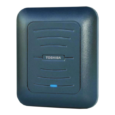
Dekolink DEKO2408 User manual

© Dekolink Wireless Ltd.—All Rights Reserved Rev. 2.00


ABOUT THIS MANUAL
This Product Manual provides the following information:
•Description of the Mini Repeater
•Procedures for setup, configuration and checking the
proper functioning of the Mini Repeater
•Maintenance and troubleshooting procedures
TO WHOM IT IS INTENDED:
This Product Manual is intended for experienced technicians and engineers. It is
assumed that the customers installing, operating, and maintaining Dekolink Mini
Repeaters are familiar with the basic functionality of Repeaters.
NOTICE Confidential - Authorized Customer Use
This document may be used in its complete form only and is solely for the use of
Dekolink Wireless Ltd. employees and authorized Dekolink Wireless Ltd.
channels or customers. The material herein is proprietary to Dekolink Wireless
Ltd. Any unauthorized reproduction, use or disclosure of any part thereof is
strictly prohibited.
All trademarks and registered trademarks are the property of their respective
owners.
DISCLAIMER OF LIABILITY
Contents herein are current as of the date of publication. Dekolink Wireless Ltd.
reserves the right to change the contents without prior notice. The information
furnished by Dekolink Wireless Ltd. in this document is believed to be accurate
and reliable. However, Dekolink Wireless Ltd. assumes no responsibility for its
use. In no event shall Dekolink Wireless Ltd. be liable for any damage resulting
from loss of data, loss of use, or loss of profits and Dekolink Wireless Ltd. further
disclaims any and all liability for indirect, incidental, special, consequential or
other similes damages. This disclaimer of liability applies to all products,
publications and services during and after the warranty period.
EXCLUSIVE REMEDIES
The remedies provided herein are the Buyer’s sole and exclusive remedies.
Dekolink Wireless Ltd. shall not be viable for any direct, incidental, or
consequential damages, whether based on contract, tort, or any legal theory.
Dekolink Wireless
International Headquarters
16 Bazel St., Kiryat-Arieh,
Petah-Tikvah 49001
ISRAEL
Tel.: +972 3 918-0180
Fax: +972 3 918-0190
E-mail: marketing@dekolink.com
Website: www.dekolink.com
Dekolink USA, Inc.
Americas Group
550 Club Drive
Ste. 470
Montgomery, Texas 77316-3094, USA
Tel: +1-936-582-7100
Fax: +1- 936-582-7108
Website: www.dekolink.com
© Dekolink Wireless Ltd
Publication No.: 308-2005 Rev. 2.00S

DEKOLINK WIRELESS LTD. MINI REPEATER PRODUCT MANUAL
Page b Proprietary Data Pub. 308-2005 Rev. 2.00S
SAFETY WARNINGS AND ADMONISHMENTS
Throughout this manual, important safety warnings and admonishments are included to
warn of possible hazards to persons or equipment. A safety warning identifies a possible
hazard and then describes what may happen if the hazard is not avoided. The safety
warnings – in the form of Dangers, Warnings and Cautions must be followed at all
times. These warnings are flagged by the use of a warning icon, usually the triangular
alert icon seen below. The exclamation point within the triangular alert icon is intended
to warn the operator or service personnel of operation and maintenance from factors
elating to the product and its operating environment, which could pose a safety hazard.
GENERAL SAFETY WARNINGS CONCERNING USE OF THIS SYSTEM
Always observe standard safety precautions during installation, operation and
maintenance of this product. Only a qualified and authorized personnel should carry out
adjustment, maintenance or repairs to the components of this equipment.
Danger: Electrical Shock
This equipment is intended to be installed indoor. Wet conditions increase the
potential for receiving an electric shock when installing or using electrically
powered equipment. To prevent electrical shock when installing or modifying
the system power wiring, disconnect the wiring at the power source before
working with uninsulated wires or terminals.
Caution: RF Exposure
Installation of an antenna must comply with the FCC RF exposure
requirements. See paragraph 4.9.

PRODUCT MANUAL MINI REPEATER DEKOLINK WIRELESS LTD.
Pub. 308-2005 Rev. 2.00S Proprietary Data Page c
GLOSSARY The following is a list of abbreviations and terms used throughout this document.
Abbreviation/Term Definition
AGC Automatic Gain Control
ALC Automatic Level Control
ATR Acceptance Test Results
BTS Base Transceiver Station
DAS Distributed Antenna System
DL Downlink
Downlink The path covered from the Base Transceiver
Station (BTS) to the subscribers/service area
via the Repeater
ESD Electro-Static Discharge
iDEN Integrated Digital Enhanced Network
IF Intermediate Frequency
MN Model Number
NMT Network Management Tool
PLL Phased Locked Loop
POTS Plain Old Telephone System
RF Radio Frequency
RMS Repeater Management System
SALC Smart-ALC (Automatic Level Control)
SIM Subscriber Identification Module
SQE Signal Quality Estimate
UL Uplink
Uplink The path covered from the subscribers/service
area to the Base Transceiver Station (BTS)
via the Repeater
VSWR Voltage Standing Wave Ratio


DEKOLINK WIRELESS LTD. MINI REPEATER DEKO2408-09 PRODUCT MANUAL
Pub. 308-2005 Rev. 2.00S Proprietary Data Page i
CONTENTS
1. INTRODUCTION ...................................................................................... 1
1.1 General........................................................................................................................1
1.2 Applications.................................................................................................................1
1.3 Description...................................................................................................................1
1.4 Controls and Indicators ...............................................................................................2
1.5 Features.......................................................................................................................4
1.6 Models and Frequencies...............................................................................................5
1.7 Unpacking and Inspection............................................................................................6
2. FUNCTIONAL DESCRIPTION................................................................. 7
2.1 General........................................................................................................................7
2.2 Functional Description.................................................................................................7
3. SPECIFICATIONS .................................................................................... 9
3.1 General........................................................................................................................9
3.2 Electrical Specifications ...............................................................................................9
3.3 General Specifications..................................................................................................9
3.4 Mechanical Specifications ............................................................................................9
3.5 Environmental Specifications.....................................................................................10
3.6 Connectors.................................................................................................................10
4. INSTALLATION AND TURN-ON........................................................... 11
4.1 General......................................................................................................................11
4.2 Safety Instructions.....................................................................................................11
4.3 Installation Site Considerations..................................................................................11
4.4 Tools and Materials ...................................................................................................11
4.5 Installation Procedures ..............................................................................................11
4.6 Antenna Installation Site - Considerations .................................................................13
4.7 Connection to Antennas and to Power........................................................................13
4.8 Turn-On Procedures..................................................................................................14
4.9 Donor Antenna Alignment .........................................................................................15
4.10 RF Exposure Warning .............................................................................................16
5. DAISY-CHAINED MINI-REPEATERS ................................................... 17
6. SETUP ..................................................................................................... 18
6.1 General......................................................................................................................18
6.2 Local Mode Connection .............................................................................................18
6.3 Repeater Management System (RMS)........................................................................19
6.4 RMS650 – Main Screen Description...........................................................................21
6.5 Selecting Deko2408 or 2409........................................................................................22
6.6 Mini-Repeater Setup..................................................................................................25
6.7 Selecting the Operating Sub-Bands............................................................................28
6.8 Finalizing the Operation Procedures..........................................................................32

MINI REPEATER PRODUCT MANUAL DEKOLINK WIRELESS LTD.
Page ii Proprietary Data Pub. 308-2005 Rev. 2.00S
6.9 Alarms Screen............................................................................................................33
6.10 Configuration Screen................................................................................................34
6.11 Exiting the RMS Software ........................................................................................35
7. MAINTENANCE AND TROUBLESHOOTING........................................36
7.1 General ......................................................................................................................36
7.2 Periodic Maintenance.................................................................................................36
7.3 Failure Display...........................................................................................................36
7.4 Status LEDs Troubleshooting.....................................................................................36
7.5 Mini-Repeater Alarms................................................................................................38
7.6 Dry-Contact Alarms...................................................................................................42
APPENDIX A: DEKOLINK WIRELESS LIMITED WARRANTY ................................43

DEKOLINK WIRELESS LTD. MINI REPEATER DEKO2408-09 PRODUCT MANUAL
Pub. 308-2005 Rev. 2.00S Proprietary Data Page 1
1. INTRODUCTION
1.1 GENERAL
Dekolink’s Mini Repeaters are high selectivity amplifiers that amplify signals
bi-directionally between base stations and mobile handsets, in cellular and other
wireless systems.
Dekolink’s Mini Repeaters provide high selectivity capability by employing an
advanced up/down conversion and Intermediate Frequency (IF) Surface
Acoustic Waves (SAW) filtering architecture. This advanced architecture
offers distinct advantages over conventional band selective Repeaters.
These Mini Repeaters feature a "plug-and-play" capability for fast response and
immediate solution to your coverage needs. These repeaters can be operational
flexible by adding the optional SAW Switcher which enables to set one of two
of two pre-determined different frequency bands, thus providing two units in
one Repeater.
1.2 APPLICATIONS
Dekolink’s Mini Repeaters are highly suitable for deployment in dense urban
environments, tunnels and other areas where physical structures cause low field
strengths. These Mini Repeaters introduce new system capabilities that enable
a wide variety of applications particularly when adjacent band selectivity and/or
very high spectral purity are required. The Repeaters provide a solution to
situations in which flexible, high quality and high resolution filtering methods
are necessary.
Dekolink’s Mini Repeaters help improve in-building coverage, and can perform
as hole-filler in particular spots in a residence such as parking lots, tunnels, etc.
1.3 DESCRIPTION
Small, lightweight and easy-to-install, this Mini Repeater addresses network
coverage problems quickly and straightforwardly (see Figure 1).
1.3.1 Smart-ALC
The downlink path includes Dekolink’s Smart Automatic Level Control
(Smart-ALC) control algorithm to ensure linear operation of the Repeater. This
feature automatically adjusts the Repeater gain, reducing it in case of over the
limit power output, or boosting it to maintain maximum gain utilization.
The Smart-ALC automatically maintains downlink and uplink gain balance,
this preventing oscillation in case of insufficient isolation. It prevents “cell
coverage shrinking” while maintaining the power amplifier linearity.
Dekolink’s Mini Repeaters comply with relevant standards in accordance with
their application, such as CDMA 2000, FCC, ETSI, etc.
1.3.2 Switchable Bandwidth
The internal SAW Switcher enables to implement the Switchable Bandwidth
option. This function enables more efficient and better adaptability of the
Repeater to your needs. This capability enables you to install the Repeater in

PRODUCT MANUAL MINI REPEATER DEKO2408-09 DEKOLINK WIRELESS LTD.
Page 2 Proprietary Data Pub. 308-2005 Rev. 2.00S
different operation environments or adapt it to the evolving operating
environment.
The Switchable Bandwidth function provides you the capability to set the
Repeater to one out of three pre-determined different frequency bandwidths, as
per requirement. At each frequency band, the operating center frequency can
slide all over the application bandwidth.
This capability lowers operating costs and reduces complex logistics by
removing the need to install a different Repeater at separate locations with
different allocated bandwidth, or similarly, in case the allocated bandwidth
evolves at the installation site, you are not required to replace the installed
Repeater, just set the second bandwidth.
1.4 CONTROLS AND INDICATORS
The High selectivity Mini Repeater includes one power adjustment selector and
three status LEDs in its front panel (see Figure 2).
Figure 1: Mini Repeater
1.4.1 Power Selector
The Power selector enables to set the output power in accordance with the local
requirements, during the setup and during troubleshooting of the Repeater.

DEKOLINK WIRELESS LTD. MINI REPEATER DEKO2408-09 PRODUCT MANUAL
Pub. 308-2005 Rev. 2.00S Proprietary Data Page 3
1.4.2 Status LEDS
The status LEDs provide indication on the Repeater operation. Their functions
are (see Figure 2):
•DL (Downlink) – Left-hand LED – Downlink path
status indication
•Power – Center LED – Power\ Major alarms status
indication
•UL (Uplink) – Right-hand LED – Uplink path status
indication
•
These LEDs can display the statuses in three colors: Green, Orange and Red as
well as blinking.
Figure 2: Mini Repeater Indicators Panel
These LEDs indicate the operating status of the system:
•At turn on, the LEDs show the built-in test
procedures: The LEDs turn from orange to red to
green.
•During normal operation, all LEDs are green
•LEDs in red indicate a major malfunction.
Orange displays high input power.
Blinking green shows low power transmission.
Refer to Chapter 7 for a description of the different alarm statuses.

PRODUCT MANUAL MINI REPEATER DEKO2408-09 DEKOLINK WIRELESS LTD.
Page 4 Proprietary Data Pub. 308-2005 Rev. 2.00S
1.5 FEATURES
1.5.1 General
Some of the High selectivity Mini Repeater features are listed below:
•1/4 W (+24 dBm) Uplink and Downlink composite
power
•80 dB RF gain
•High linear amplification
•High selectivity – SAW filtering
•Excellent out-of-band interference prevention
•High spectral purity
•SAW Switcher capability
•Unique microprocessor controlled features:
•-Smart ALC, for in-network transparent operation
•-Remote or local control and alarms (software
enabled) option
•-Built-in power measurement and RSSI indication.
The High Selectivity Mini Repeater is also a compact built Repeater, of small
dimensions, with excellent power to volume ratio. It boasts a stylish design for
indoor installation, and can be easily installed on a flat wall.

DEKOLINK WIRELESS LTD. MINI REPEATER DEKO2408-09 PRODUCT MANUAL
Pub. 308-2005 Rev. 2.00S Proprietary Data Page 5
1.6 MODELS AND FREQUENCIES
Dekolink’s High selectivity Mini Repeater can be provided in several models,
as listed below.
The operating frequency ranges depend on the type and model, as specified in
the following table.
Repeater Model Model Number Downlink
(MHz) Uplink
(MHz) Frequency
Separation
(MHz)
iDEN / SMR -
One of two sub bands MW-CCSR-SMR-
1W80-XX-YY 851-869 806-824 45
GSM -
One of two sub bands MW-CCSR-GSM-
1W80-XX-YY 935-960 890-915 45
CDMA/TDMA/N-AMPS-
One of two sub bands MW-CCSR-800AB-
1W80-XX-YY 869-894 824-849 45
GSM -
Two sub bands at ZZ
separation
MW-CCSR-GSM-
1W80-XX-YY-SZZ 935-960 890-915 45
CDMA/TDMA/N-AMPS
Two sub bands at ZZ
separation
MW-CCSR-800AB-
1W80-XX-YY-SZZ 869-894 824-849 45
XX, YY- The two frequency sub-bands, selected by the SAW Switcher (XX only for single
sub band)
ZZ – Frequency separation between the sub bands for dual block operation
iDEN / SMR - 900 MHz
(*) MW-CCSR-SMR-
1W80-PS9 935-941 896-902 39
iDEN / SMR - 800 MHz
(*) (Full Band) MW-CCSR-SMR-
1W80-PS8
806-824 851-869 45
CDMA Band A (*) MW-CCSR-800A-
1W80 870-880 825-835 45
CDMA Band AA’ (*) MW-CCSR-800AA-
1W80 870-880
890-891.5 825-835
845-846.5 45
CDMA/TDMA/GSM
Band B (*) MW-CCSR-800B-
1W80 880-890 835-845 45
CDMA/TDMA
Band BB’ (*) MW-CCSR-
800BB’-1W80 880-894 835-849 45
CDMA/TDMA
Full Band AB (*) MW-CCSR-800AB-
1W80 880-894 835-849 45
(*) Specific partial band
MW-CCSR-ESMR-1W80- 15-7-5 =DEKO 2408 commercial model
DownLink 851 - 869MHz / Uplink 806-824MHz - Frequency Separation 45MHz

PRODUCT MANUAL MINI REPEATER DEKO2408-09 DEKOLINK WIRELESS LTD.
Page 6 Proprietary Data Pub. 308-2005 Rev. 2.00S
1.7 UNPACKING AND INSPECTION
This section provides information for unpacking and inspection:
•Examine the shipping container for damage before
unpacking the unit. Perform a visual inspection to
reveal any physical damage to the equipment.
•Verify that the equipment is complete, as listed below
and under a packing slip. Contact Dekolink Wireless
Ltd if any of this equipment is missing.
Your Mini Repeater comes with the following equipment:
•Mini-Repeater
•AC cable [6 ft.]
•RS232 cable [6 ft.]
•Mini-Repeater Product Manual
•Acceptance Test Results (A.T.R.)
•Packaging Box

DEKOLINK WIRELESS LTD. MINI REPEATER DEKO2408-09 PRODUCT MANUAL
Pub. 308-2005 Rev. 2.00S Proprietary Data Page 7
2. FUNCTIONAL DESCRIPTION
2.1 GENERAL
The High selectivity Mini Repeater functional operation is based on a duplexed
path configuration. In each path, the signal is down-converted to an
Intermediate Frequency (IF); filtered by a Surface Acoustic Wave (SAW) filter
and up-converted back. This configuration gives sharp out of band attenuation
for improved isolation between the receiving and transmitting paths.
2.2 FUNCTIONAL DESCRIPTION
2.2.1 Signal Path
The following process is performed in both the Uplink and Downlink paths of
the Repeater (see Figure 3).
The incoming RF signal from either the Base antenna (from the BTS) or from
the Mobile antenna (from the mobile handset) enters the Repeater and is first
filtered by the Duplexer. The incoming signal is amplified by an Automatic
Gain Control (AGC) amplifier (AMP). The signal is then down-converted to an
Intermediate Frequency (IF).
Figure 3: Mini Repeater - Block Diagram
The input IF signal is next filtered by a Surface Acoustic Wave (SAW) filter.
After filtration, the signals are converted to RF signals by the Up-Converter.
This processing path provides sharp out-of-band attenuation that improves the
isolation between the receiving and transmitting paths.

PRODUCT MANUAL MINI REPEATER DEKO2408-09 DEKOLINK WIRELESS LTD.
Page 8 Proprietary Data Pub. 308-2005 Rev. 2.00S
2.2.2 Power Monitoring- Smart-ALC
Next, the output RF signal is amplified by a power amplifier and combined by a
duplexer before output.
The power amplifier includes power-monitoring circuits with Automatic Level
Control (ALC). The ALC prevents excessive output power while maintaining
the power amplifier linearity.
The Repeater also includes Dekolink's Smart-ALC algorithm for gain control.
This algorithm adjusts the gain of the Repeater paths in case of insufficient
isolation. This feature prevents oscillation while maintaining gain utilization in
the linear range operation.
To reset the Repeater to its highest gain value, it is sufficient to simply turn the
Repeater power off then on.
2.2.3 SAW Switcher
The SAW Switcher enables you to select one out of three frequency bands in
order to adapt the Repeater to the site bandwidth allocation. The selection is
software enabled (see Chapter 6).
2.2.4 Control and Monitoring
The Mini-Repeater operation is controlled by a microprocessor. The processor
monitors the Repeater function and controls the alarm LEDs located on the
Mini Repeater front panel.
2.2.5 Protection
The Mini-Repeater also includes protection against high V.S.W.R. and difficult
operation conditions. An auto recovery mechanism returns the unit to normal
operation, after power or other failures.

DEKOLINK WIRELESS LTD. MINI REPEATER DEKO2408-09 PRODUCT MANUAL
Pub. 308-2005 Rev. 2.00S Proprietary Data Page 9
3. SPECIFICATIONS
3.1 GENERAL
This section provides the electrical, mechanical and environmental
specifications of the
Note
Specifications are subject to change without notice.
3.2 ELECTRICAL SPECIFICATIONS
Parameter Downlink Uplink
Frequency Range See paragraph 1.6 See paragraph 1.6
Passband Gain 80 ±2 dB 80 ±2 dB
Passband Ripple ±1.5 dB ±1.5 dB
Gain Attenuation Range
(internal) 0 to 31 dB
(in 1 dB steps) 0 to 31 dB
(in 1 dB steps)
Output Power (Composite
Power) 1/4 W (+24 dBm) 1/4 W (+24 dBm)
Noise Figure @ Max. Gain 6 dB Typical 6 dB Typical
Propagation Delay <5 µsec <5 µsec
3.3 GENERAL SPECIFICATIONS
Parameter Range
Power Supply 220/110 VAC
Power Consumption 35 W
Total RF Input Power (no damage) +10 dBm
Impedance Level 50 Ohm
V.S.W.R. 1.5:1
3.4 MECHANICAL SPECIFICATIONS
Parameter Range
Size H x W x D 310 x 270 x 70 mm (12.2 x 10.6 x 2.8 inch)
Weight Approximately 6 kg (13.2 lbs)

PRODUCT MANUAL MINI REPEATER DEKO2408-09 DEKOLINK WIRELESS LTD.
Page 10 Proprietary Data Pub. 308-2005 Rev. 2.00S
3.5 ENVIRONMENTAL SPECIFICATIONS
The Mini-Repeater is designed for indoor installation. It meets the European
IP54 standard for indoor equipment.
Condition Value
Operating temperature -20 °C to +50 °C
Storage temperature -30 °C to +80 °C
3.6 CONNECTORS
The Repeater interfaces with a Base antenna port and a Mobile antenna port
(see Figure 4). It includes six external connectors in its bottom panel, as
described below.
Connector Type
RF Connectors: BASE / MOBILE N-type, Female
DC Power (9 V) Circular DIN, 4-pin
Communications RS-232
Coupling Connectors (-20 dB):
Base / Mobile SMA
Alarms Dry Contacts- 3 pins;
Normally close (NC),
Common,
Normally Open (NO)
Figure 4: Mini Repeater – Connectors Panel

DEKOLINK WIRELESS LTD. MINI REPEATER DEKO2408-09 PRODUCT MANUAL
Pub. 308-2005 Rev. 2.00S Proprietary Data Page 11
4. INSTALLATION AND TURN-ON
4.1 GENERAL
The small, lightweight High selectivity Mini Repeater is easy-to-install. It requires
no measurement tools in almost every setting.
4.2 SAFETY INSTRUCTIONS
Before installing the Repeater, review the following safety information:
•Follow all local safety regulations when installing the
Repeater
•Only qualified personnel are authorized to install and
maintain the Repeater
•Follow Electro-Static Discharge (ESD) precautions.
4.3 INSTALLATION SITE CONSIDERATIONS
The Mini-Repeater is provided with back panel flanges for easy installation on
any surface (see Figure 5). It is recommended to install the Mini-Repeater on a
flat back rigid surface. The installation site for the Mini-Repeater should take
into consideration the following conditions:
•The Repeater should be installed in a ventilated and easy-to-reach
area
•The Repeater is convection cooled so airflow and alternation
should be possible.
4.4 TOOLS AND MATERIALS
No measurement tools are required for almost all settings. No special tools are
necessary. However, a standard, professional, tools box is required for the
installation procedures.
4.5 INSTALLATION PROCEDURES
The wall mount installation is the preferred method of installation for the
Repeater. Determine the location of the Repeater on the wall. The location
should be at normal eye level height, above ground.
Proceed as follows:
1. Mark the three drilling holes on the surface of the wall based on the
mounting holes on the Repeater chassis – see Figure 5
2. Drill the appropriate three (3) holes in the wall
3. Align the housing so that the mounting brackets fit into the holes in
the wall
4. Use hex-head bolts, and washers to secure the enclosure firmly to the
wall.
Note
Bolts and washers are not supplied with the Repeater

PRODUCT MANUAL MINI REPEATER DEKO2408-09 DEKOLINK WIRELESS LTD.
Page 12 Proprietary Data Pub. 308-2005 Rev. 2.00S
Figure 5: Mini-Repeater – Dimensions
This manual suits for next models
1
Table of contents
Other Dekolink Repeater manuals
