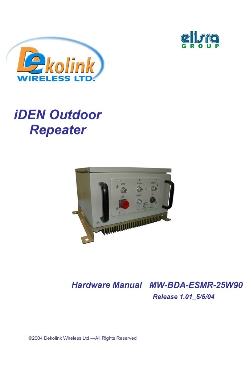
Dekolink Deko3108S User manual

© Dekolink Wireless Ltd.—All Rights Reserved
Rev. B


DEKOLINK WIRELESS LTD. DEKO3108S MIDI REPEATER PRODUCT MANUAL
P/N 300XC10031 Rev. BProprietary Data Page i
ABOUT THIS MANUAL
This Product Manual describes the Deko3108S Repeater and provides information on the
setup, configuration and troubleshooting procedures of the 800 MHz iDEN midi-repeater.
TO WHOM IT IS INTENDED:
This Product Manual is intended for experienced technicians and engineers. It is assumed
that the customers installing, operating, and maintaining Dekolink Repeaters are familiar
with the basic functionality of repeaters.
NOTICE
Confidential - Authorized Customer Use
This document may be used in its complete form only and is solely for the use of Dekolink
Wireless Ltd. employees and authorized Dekolink Wireless channels or customers. The
material herein is proprietary to Dekolink Wireless Ltd. Any unauthorized reproduction, use
or disclosure of any part thereof is strictly prohibited.
All trademarks and registered trademarks are the property of their respective owners.
DISCLAIMER OF LIABILITY
The remedies provided herein are the Buyer’s sole and exclusive remedies. Dekolink
Wireless Ltd. shall not be viable for any direct, incidental, or consequential damages,
whether based on contract, tort, or any legal theory.
Dekolink Wireless
International Headquarters
16 Bazel St., Kiryat-Arieh,
Petah-Tikvah 49001
ISRAEL
Tel.: +972 3 918-0180
Fax: +972 3 918-0190
Website: www.dekolink.com
Dekolink USA, Inc.
Americas Group
550 Club Drive
Ste. 470
Montgomery, Texas 77316-3094, USA
Tel: +1-936-582-7100
Fax: +1- 936-582-7108
Website: www.dekolink.com
© Dekolink Wireless Ltd
P/N 300XC10031 Rev. B

PRODUCT MANUAL DEKO3108S MIDI REPEATER DEKOLINK WIRELESS LTD.
Page ii Proprietary Data P/N 300XC10031 Rev. B
SAFETY WARNINGS
Throughout this manual, important safety warnings are included to warn of possible hazards
to persons or equipment. A safety warning identifies a possible hazard and then describes
what may happen if the hazard is not avoided. The safety warnings –in the form of
Dangers, Warnings and Cautions must be followed at all times. These warnings are flagged
by the use of a warning icon, usually the triangular alert icon seen below. The exclamation
point within the triangular alert icon is intended to warn the operator or service personnel of
operation and maintenance from factors related to the product and its operating
environment, which could pose a safety hazard.
GENERAL SAFETY WARNINGS CONCERNING USE OF THIS SYSTEM
Always observe standard safety precautions during installation, operation and maintenance
of this product. Only a qualified and authorized personnel should carry out adjustment,
maintenance or repairs to the components of this equipment.
DANGER:ELECTRICAL SHOCK
This equipment is intended to be installed indoor. Wet conditions increase the potential for
receiving an electric shock when installing or using electrically powered equipment.
To prevent electrical shock when installing or modifying the system power and GND terminal
wiring, disconnect the wiring at the power source before working with un-insulated wires or
terminals.
CAUTION:RF EXPOSURE
Installation of an antenna must comply with the FCC RF exposure requirements.
WARNING:RESTRICTED ACCESS LOCATION
Access to the Dekolink Repeater installation location is restricted to SERVICE PERSONNEL and to
USERS who have been instructed on the restrictions and the required precautions to be taken.
The Dekolink Repeater can only be opened using a TOOL or lock and key, and only upon
authorization from the person responsible for the location where the Repeater is installed.
NOTICE:CMU/CCD BATTERY
The CMU/CCD battery is not replaceable.

DEKOLINK WIRELESS LTD. DEKO3108S MIDI REPEATER PRODUCT MANUAL
P/N 300XC10031 Rev. BProprietary Data Page iii
ATTENTION:UL COMPLIANCE REQUIREMENTS
Select a power supply cord that is UL listed or CSA Certified: 3-Conductor, 18AWG, SJT with
a length between 1.5m and 4.5m, terminated in a molded on plug cap rated 250V, 15A and
matching connector with 600V, 12A, or equivalent.
The socket-outlet should be installed near the equipment and be easily accessible.
STANDARDS AND COMPLIANCES
UL 60950

PRODUCT MANUAL DEKO3108S MIDI REPEATER DEKOLINK WIRELESS LTD.
Page iv Proprietary Data P/N 300XC10031 Rev. B
REVISION HISTORY
The revision history for this document is shown in Table 1.
Table 1: Revision history
P/N Revision Date Description
300XC10031 A 07-July-2008 Initial Version
;&%$SU&RPSRVLWH2XWSXW3RZHU

DEKOLINK WIRELESS LTD. DEKO3108S MIDI REPEATER PRODUCT MANUAL
P/N 300XC10031 Rev. BProprietary Data Page v
CONTENTS
About This Manual................................................................................................................i
To Whom It Is Intended:.......................................................................................................i
Notice.....................................................................................................................................i
Disclaimer of Liability...........................................................................................................i
Safety Warnings...................................................................................................................ii
General Safety Warnings Concerning Use of This System.............................................ii
Standards and Compliances .............................................................................................iii
Revision History..................................................................................................................iv
1INTRODUCTION..............................................................................................................7
1.1 Features..............................................................................................................7
1.2 Management Connections................................................................................8
1.3 Smart-ALC Function..........................................................................................8
1.4 Deko3108S Interfaces .....................................................................................10
1.5 Locking.............................................................................................................12
2Site and Installation Requirements ............................................................................13
2.1 Power Requirements.......................................................................................13
2.2 Grounding Wires Requirements ....................................................................13
2.3 Antenna Requirements...................................................................................13
2.4 Pre-Installation Safety Instructions...............................................................14
2.5 Installation Location, Environment and Cables...........................................14
3Installing the Repeater.................................................................................................15
3.1 Overview...........................................................................................................15
3.2 Unpacking ........................................................................................................15
3.3 Required Tools and Materials ........................................................................16
3.4 Mounting the Deko3108S................................................................................16
3.5 Grounding ........................................................................................................22
3.6 Power Up..........................................................................................................23
3.7 Antennas Installation and Connections........................................................23
4Getting Started..............................................................................................................26
4.1 Open a Local Session to the Repeater..........................................................26
4.2 Login to the Repeater......................................................................................27
4.3 Adjusting the Signal Level, Gain and Noise.................................................29
4.4 Configuring the Filter Switch .........................................................................30
4.5 Viewing alarms ................................................................................................32
4.6 Configuring the Parameters for an External Modem...................................34

PRODUCT MANUAL DEKO3108S MIDI REPEATER DEKOLINK WIRELESS LTD.
Page vi Proprietary Data P/N 300XC10031 Rev. B
4.7 Setting Date and Time.....................................................................................35
4.8 Reset the Repeater..........................................................................................35
4.9 Remote Wireless Management Connections................................................36
5Navigating the DekoLink web management Application .........................................37
5.1 Navigating the User Interface.........................................................................37
5.2 Repeater Network and Communication Parameters ...................................39
5.3 Monitoring Alarms and Troubleshooting......................................................40
5.4 Deko-CMU Alarms Log....................................................................................42
5.5 Viewing Repeater Information........................................................................43
6ADMINISTRATION.........................................................................................................45
6.1 Managing Users...............................................................................................45
6.2 Configuration Backup, Restore and Upload.................................................47
6.3 Repeater Software Upgrade ...........................................................................50
Appendices: .......................................................................................................................51
Appendix a. Specifications (@+25°C).........................................................................51
Mechanical Specifications...........................................................................................51
Environmental Specifications.....................................................................................51
Appendix B: Troubleshooting.....................................................................................52
Appendix C: Dekolink Wireless Limited Warranty....................................................53

DEKOLINK WIRELESS LTD. DEKO3108S MIDI REPEATER PRODUCT MANUAL
P/N 300XC10031 Rev. BProprietary Data Page 7
1INTRODUCTION
Deko3108S is a band selective midi-repeater that supports the iDEN 800 MHz band. The
repeater is specifically designed for the operation of ESMR 800 MHz and is band
selectable in the 800 MHz range [18 MHz or 7 MHz bandwidth].
Deko3108S has switchable and tunable IF-SAW filters. These enable highly accurate
out-of-band-rejection and provide simple, fast procedures for adjusting the pass band
according to the 800 MHz rebanding requirements.
Deko3108S includes the SmartALC power control algorithm that automatically optimizes
the gain setting by learning the actual range of RSSI levels over a user-specified period
of time. The SmartALC algorithm prevents oscillations, reduces the amount of isolation
required by the system and optimizes the system to minimize noise rise at the donor cell
site.
Intuitive Web access monitoring and management GUI is accessible via a local Ethernet
connection (using a cross-cable). An option for remote wireless communication
connection (via a separately purchased modem) is also available.
Figure
1-1: Deko3108S iDEN Midi-Repeater
1.1 FEATURES
•800 MHz iDEN band
•Band selectable filter switch - 18 MHz or 7 MHz bandwidth
•Supports SMR technologies
•80 dB RF gain
•24 dBm Uplink composite power
•34dBm Downlink composite power
•High linear amplification
•High spectral purity
•Highly accurate frequency selection
•Excellent out-of-band interference prevention
•IF-SAW filtering – tunable, sharp out-of-band rejection

PRODUCT MANUAL COMPACT REPEATER DEKO3108S DEKOLINK WIRELESS LTD.
Page 8 Proprietary Data P/N 300XC10031 Rev. B
•Mechanism for tunable rejection of interference from adjacent cellular and paging
frequencies
•SmartALC™ technology
•Prevents oscillations and balances coverage
•Automatically sets optimum gain
•Ensures transparent network operation
•Software setup of bandpass filter
•Remote Web access monitoring and control – option for Wireless modem
•Built-in power measurement and RSSI indication
1.2 MANAGEMENT CONNECTIONS
You can connect to the Repeater using either:
•Local connection to the Ethernet port using a
cross-cable
•Wireless remote connection – using an external modem connected to the Ethernet
port using a
cross-cable
(modem is purchased separately)
1.3 SMART-ALC FUNCTION
1.3.1 SALC Function
The iDEN midi-repeater includes the Smart Automatic Level Control (ALC) function on
both the Uplink and Downlink power amplifiers to prevent output power from exceeding
maximum allowed output power.
The amplifier includes a directional coupler and a detector that monitor the output
power. The ALC mechanism samples the output power, and decouples and rectifies it.
The ALC mechanism sends a feedback signal to a voltage variable attenuator (VVA)
that, whenever a high input signal is received, attenuates the signal level so that the
output power of the amplifier does not exceed the preset limit.
1.3.2 SALC Description
The Smart Automatic Level Control (Smart-ALC) is an innovative solution for automatic
repeater gain adjustment. Combined with advanced control algorithms, SALC can
perform gradual learning of traffic load characteristics and adjust the Repeater RF Gain
to an optimal value.
Some of the SALC advantages are:
•Network friendly: The SALC periodically learns traffic conditions and set the gain
so that at maximal traffic the repeater output is at maximal value. In all other cases
the gain is constant and the output power follows the BTS fluctuations. This feature
introduces system transparency – the mobile using the repeater is not affected by
repeater existence. Repeaters that blindly amplify the pilot code (minimal
transmission) of a certain base station to maximum output power might generate
network problems (they unnecessarily increase the noise in a certain cell). By
keeping the same gain for full traffic as well as for pilot only transmissions
situations, the Dekolink SALC feature minimizes this effect.
•No adjustments are required: When installing the repeater, the standard
procedure for the technician is to tune the repeater to the desired isolation and gain
values. With SALC, the tuning procedure is accomplished automatically, thus saving

DEKOLINK WIRELESS LTD. DEKO3108S MIDI REPEATER PRODUCT MANUAL
P/N 300XC10031 Rev. BProprietary Data Page 9
precious workmanship and equipment usage time for a “plug & play” foolproof
deployment.
•Uplink and downlink balance is preserved. In previous repeaters, separate
adjustments are required for the uplink and downlink. This repeater requires just
one adjustment for both channels. If the gain of downlink path changes by some
value, the uplink path is changed by the same value. Both channels have to be
balanced for the proper seamless integration of the repeater in the network.
Unbalanced operation bares the risk of reducing the dynamic range of the base
station itself.
•Reduction of isolation problems: .This repeater does not oscillate. Whenever
the isolation drops for some reason the repeater automatically senses the
oscillations and automatically reduces the gain in accordance with the new isolation
conditions. Once the isolation problem is solved the repeater automatically raises
the gain again. This operation is remotely monitored, and if required, remote
controlled.
SALC - Summary: Conventional repeaters often interfere in the network when strong
traffic raises the repeater input signal level, which as a result activates the ALC
algorithm of the system. Once under ALC, the conventional system is no longer in its
linear dynamic range, hence creating interferences in the cell shrinking or expanding
procedures. The Smart ALC solves this problem and thus reduces the need for
adjustments. The repeater does not interfere with the network shrinking or expanding
processes and thus becomes “network friendly“.
This automatic operation practically removes the need to make initial settings for
maximal traffic load conditions and eliminates the need for numerous site visits to take
care of Gain adjustment.
SALC also reduces isolation problems and maintains Uplink/Downlink balance.

PRODUCT MANUAL COMPACT REPEATER DEKO3108S DEKOLINK WIRELESS LTD.
Page 10 Proprietary Data P/N 300XC10031 Rev. B
1.4 DEKO3108S INTERFACES
Deko3108S is housed in an enclosure with a securely locked door for easy access to the
internal components for connections, adjustment and for service and maintenance.
Most of the required interfaces are located externally; however, the
communication
ports
and the manual RF power selector (for service personnel) are located internally
and are accessed by
opening
the Repeater door.
1.4.1 Ports
The antenna and power connections are located on the underside of the Repeater as
illustrated below.
Figure
1-2. Deko3108S Front Panel
The following table provides a description of the front panel ports and connections.
Group Connectors
BASE Donor antenna connections. See 3.7.2.
MOBILE Service antenna connections. See 3.7.2.
100 to 240 VAC Connection to AC power supply
AUX PWR 12VDC output power for powering external modem. See 4.9.
ETHERNET/EXT/ A Curtained slot protecting the Ethernet cable through which the
Ethernet cable is to the CMU module (see 1.4.2.1). It is required to
open the cover in order to connect to the ports.
Service
antenna
connections
Power
connection
100-240 VAC
Donor
antenna
connections
Curtained slot –
Ethernet port
Power to
external modem WARNING: Do not unscrew
while power is connected

DEKOLINK WIRELESS LTD. DEKO3108S MIDI REPEATER PRODUCT MANUAL
P/N 300XC10031 Rev. BProprietary Data Page 11
1.4.2 Internal Interfaces
This section describes the Repeater interfaces that are accessed by opening the
Repeater. There are two such interfaces:
•The Ethernet port
•Power level selector – for service personnel only. This connector is relevant only if
the option is enabled from the Web GUI application 4.3.
1.4.2.1 Ethernet Port
During installation, you will be required to open the enclosure door in order to access
the
Ethernet
communication port located (on the CMU unit as illustrated below).
Note: The Ethernet communication port is the only port that is relevant to the user.
Figure
1-3. CMU Front Panel
1.4.2.2 Internal Power Selector (for service personnel)
The Max Gain is factory set to its minimum value by default. The RF power level can be
modified either through the GUI (default - 4.3.) or through the internal selector located
in the Repeater (service personnel only).
The Repeater is factory set to allow this configuration
only through the GUI – the
internal selector is disabled.
In order to use the selector in the unit to set the CDMA
power level, the option must first be enabled in the GUI by setting the LBDA Params
Mask (section 4.3); otherwise any changes in setting via this switch are not relevant.
NOTE: The UL and DL LEDs can be used to provide some indication of the UL and DL
signal levels. However, it is recommended to use the WEB access application advanced
monitoring capabilities to monitor and troubleshoot the Repeater.
Ethernet port connection
(Accessed by opening
Repeater door and inserting
cable through curtained slot)

PRODUCT MANUAL COMPACT REPEATER DEKO3108S DEKOLINK WIRELESS LTD.
Page 12 Proprietary Data P/N 300XC10031 Rev. B
1.4.3 Internal Indicators
•Power – Lights up when Repeater is connected to power
•DL – Indicates level of signal from the (relevant) BTS donor antenna
•UL - Level of signal from the (relevant) BTS donor antenna
Figure
1-4: Connections Unit –Power Selector and Indicators
LED Colors
Refer to Appendix B: Troubleshooting for detailed information on each LED indicator.
Color Description
Green Normal operation - All LEDs should be GREEN during
normal operation
Red LED Signifies a major malfunction
Orange LED Signifies high input power
Blinking Green and Blinking
Orange
Signifies low power transmission
1.5 LOCKING
The door is locked with two locks – the same key is used for both.
Figure
1-5: Deko3108S – Locks

DEKOLINK WIRELESS LTD. DEKO3108S MIDI REPEATER PRODUCT MANUAL
P/N 300XC10031 Rev. BProprietary Data Page 13
2SITE AND INSTALLATION REQUIREMENTS
This section describes the power, antenna and site requirements for the Repeater
installation.
2.1 POWER REQUIREMENTS
2.1.1 Overcurrent Protection
A readily accessible, listed branch circuit over current protective device, rated 20 A,
must be incorporated in the building wiring.
2.1.2 North American Power Wiring
Select a power supply cord that is UL Listed and CSA Certified: 3 - conductor, 18 AWG,
terminated in a molded on plug cap rated 125 V, 15 A, with a minimum length of 1.5m
[six feet] but no longer than 4.5m.
2.2 GROUNDING WIRES REQUIREMENTS
Requirements for grounding wires
•Protective grounding conductor - should be aluminum with cross-section 10AWG.
•Lug of the protective grounding conductor - should be aluminum
•Washers and screw - should be high Cr stainless steel, or 12% Cr stainless steel, or
Cr on, Ni on steel, tin on steel
2.3 ANTENNA REQUIREMENTS
2.3.1 Base (Donor) Antenna
The Base (Donor) antenna is usually installed outdoors and is either a directional
antenna such as a Yagi or a Panel antenna.
Donor Antenna specifications:
•Yagi type or similar – 8 to 14 dBi gain, and features a very sharp beam pointed to
the BTS.
•Cable and jumper loss is at least 2dB.
•Example of antenna's typical specifications:
Gain: 8 dBd (=10.1 dBi)
VSWR: < 1:5:1
Impedance: 50 ohm
Installation requirements:
•The antenna should point to the direction of the base station for maximum input
power
•Verify that the antenna is in the base stations line of sight (raise the antenna if
necessary)
•Install the donor antenna at a higher level (i.e. floor) than the mobile antenna
•Must be installed at a minimum distance of 1 meter from any personnel within the
area.

PRODUCT MANUAL COMPACT REPEATER DEKO3108S DEKOLINK WIRELESS LTD.
Page 14 Proprietary Data P/N 300XC10031 Rev. B
2.3.2 Mobile (Service) Antenna
The Mobile antenna is installed indoors.
Note: Before installing the Mobile antenna, see FCC regulations for information
regarding recommended distances between the antennas and populated areas.
The following describes the requirements for an omni-directional mobile used for indoor
applications.
Specifications:
•Omni directional antenna with a 0 to 2 dBi typical gain, or wide beam with up to
4dBi gain.
•Example of omni-directional antenna specifications:
Gain: 0 to 2 dBi
VSWR: < 2:1
Impedance: 50 ohm
Installation requirements:
•Installation of this antenna must provide a minimum separation distance of 0.2 m
from any personnel within the area.
•Cable and jumper loss is at least 2dB.
2.4 PRE-INSTALLATION SAFETY INSTRUCTIONS
Before installing the Repeater, review the following safety information:
•Follow all local safety regulations when installing the Repeater.
•Only qualified personnel are authorized to install and maintain the Repeater.
•During normal operation, the Repeater door should be closed.
•Some maintenance tasks may require the iDEN midi-repeater door to be opened
while the power is on. In such cases, perform the required tasks carefully and
remember to close the Repeater cover/door when finished.
•Ground the iDEN midi-repeater with the grounding bolt located on the external
lower side of the cabinet (see 3.5).
•Do not use the grounding bolt to connect external devices.
•Follow Electro-Static Discharge (ESD) precautions.
•Before closing the iDEN midi-repeater cover, make sure no wires are in the way.
•Use low loss cables to connect the antennas to the Repeater.
2.5 INSTALLATION LOCATION,ENVIRONMENT AND CABLES
WARNING! THE REPEATER MUST ALWAYS BE INSTALLED VERTICALLY AND TOP-DOWN,TO
ALLOW FREE-FLOW OF COOLING AIR.HORIZONTAL INSTALLATION ON A BENCH FOR LONG TIME
MAY CAUSE DAMAGE TO THE REPEATER DUE TO OVER-HEATING.
•Use a suitable mounting surface, such as a rigid wall.
•Follow Electro-Static Discharge (ESD) precautions.
•Install the iDEN midi-repeater close to the service area to monitor the output power
and noise figure.
•Use low loss cables to connect the antennas to the Repeater.
•Install the Repeater in a shielded, ventilated, and easy-to-reach area – preferably at
eye level.

DEKOLINK WIRELESS LTD. DEKO3108S MIDI REPEATER PRODUCT MANUAL
P/N 300XC10031 Rev. BProprietary Data Page 15
3INSTALLING THE REPEATER
3.1 OVERVIEW
The Deko3108S installation procedure consists of the following steps:
•Mounting the supplied Mounting Fixture on wall
•Mounting the Repeater on the Mounting Fixture
•Grounding the Repeater
•Connecting the power
•Installing and connecting the antennas
Note: External modem for wireless communication is optional (see 4.9).
The following figure provides an overview of the Deko3108S connections.
3.2 UNPACKING
Upon receiving the Deko3108S unit, perform the following:
1. Examine the shipping container for damage before unpacking the unit.
2. Perform a visual inspection to reveal any physical damage to the equipment.
3. Verify that all of the equipment (listed below) is included. Otherwise contact
Dekolink Wireless Ltd.
The Deko3108S iDEN midi-repeater is shipped with the following equipment:
•Deko3108S iDEN midi-repeater - Model: MW-CSR-SMR8-3180
•Key (used to lock the repeater door)
•Mounting Fixture
•Four 5/16" NF hexagon screws (used to secure Repeater to Mounting Fixture)
•AC supply cable [6 ft.]
•LAN cable [9.8 ft.]
•User Manual (CD)

PRODUCT MANUAL COMPACT REPEATER DEKO3108S DEKOLINK WIRELESS LTD.
Page 16 Proprietary Data P/N 300XC10031 Rev. B
•Packaging box
•Power supply 12V/4A – for external modem
•AC supply cable – for external modem
3.3 REQUIRED TOOLS AND MATERIALS
The following is required in order to mount the Deko3108S Repeater:
•Mounting Fixture (supplied)
•Four 5/16" NF hexagon screws (supplied)
•Standard professional tools
•Anchor hexagon head screws (for concrete and plywood and gypsum drywall
installations) and anchor bolts (for brick wall installation). See 3.4.2.1.
3.4 MOUNTING THE DEKO3108S
3.4.1 Pre-Mounting Procedure
NOTE: The weight of the unit requires that two people mount the unit on the wall.
1. Choose the location of the Repeater on the wall according to the following criteria:
•The location should be at normal eye level height, above ground.
•Make sure to allow the door to swing completely open, and to enable easy
access to the Repeater for maintenance and on-site inspection.
2. Place the Mounting Fixture against the wall and mark the holes to be drilled – See
section 3.4.2.1 - Components for number of anchors/bolts required for each type of
wall (concrete, brick, plywood and drywall).
Figure
3-1. Mounting Fixture

DEKOLINK WIRELESS LTD. DEKO3108S MIDI REPEATER PRODUCT MANUAL
P/N 300XC10031 Rev. BProprietary Data Page 17
Figure 2. Mounting Fixture Measurements

PRODUCT MANUAL COMPACT REPEATER DEKO3108S DEKOLINK WIRELESS LTD.
Page 18 Proprietary Data P/N 300XC10031 Rev. B
3.4.2 Bracket Installation Procedure
The bracket mounting procedure differs according to the type of wall.
3.4.2.1 Components
Use the components according to the following table:
Type of wall Components
Concrete Anchor Hexagon Head Screws – Install at least 4 Zinc Plated
Steel Anchor Hexagon Head Screw with Integrated Washer, such
as FBN 8/50 Fischer Fixing Systems or compatible from other
companies. See 3.4.2.2.
Brick Anchor Bolts – Install at least 6 Zinc Plated Steel Anchor Bolt
With Integrated Washer, such as FUR 8x80 Fischer Fixing
Systems or compatible from other companies. See 3.4.2.2.
Plywood and
Gypsum Drywall
Anchor Hexagon Head Screws – Install at least 8 Zinc Plated
Steel Anchor Hexagon Head with Integrated Washer, such as
HDD-S M8x66 HILTI or compatible from other companies.
For Plywood walls – see 3.4.2.2.
For Gypsum Walls – see 3.4.2.3
3.4.2.2 Bracket Installation for Concrete, Brick and Plywood Walls
1. Using the diameter metric bit recommended by the manufacturer (anchor or bolt),
drill the required number of holes according to wall type (see 3.4.2.1) to minimum
required hole depth.
2. Remove drilling debris with a blowout bulb or with compressed air.
Note: Screws and anchors are not supplied with the Repeater.
Table of contents
Other Dekolink Repeater manuals
Popular Repeater manuals by other brands

Inventronics
Inventronics DALI REPEATER SO operating instructions
BWI Eagle
BWI Eagle AIR-EAGLE XLT PLUS Product information bulletin
Fritz!
Fritz! DVB-C Installation and operation
UGMO
UGMO UG1000 series Quick installation and start-up guide
SIIG
SIIG CE-H20N11-S1 Quick installation guide
JTL
JTL NR110 user guide
