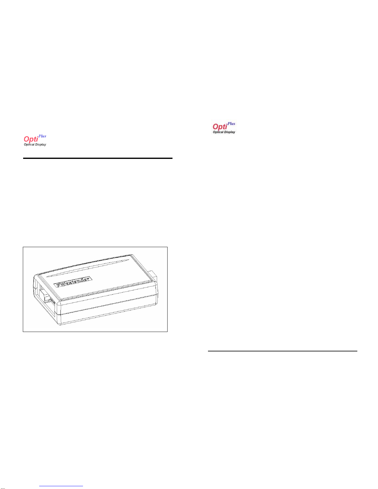
OptiPlus FWextender FWA100 Series User manual

FWextenderTM
FWA100 Series
OptiPlus,Inc. 2/15
FWextender™
IEEE1394 Optical Interface Adapter
FWA100 Series
IEEE1394 Fiber Optic Repeater
USER’S Manual
P/N : OPI –D04004RA Jan 2, 2004
Picture of FWA100 Series Model

FCC NOTICE
THIS DEVICE COMPLIES WITH PART 15 OF THE FCC FULES.
OPERATION IS SUBJECT TO THE FOLLOWING TWO CONDITION:
(1) THIS DEVICE MAY NOT CAUSE HARMFUL INTERFERENCE,AND
(2) THIS DEVICE MUSTACCEPTANY INTERFERENCE RECEIVED,
INCLUDING INTERFERENCE THAT MAY CAUSE UNDERSIRED
OPERATION.
This equipment has been tested and found to comply with the limits for a Class B digital device, pursuant to part 15 of the FCC Rules.
These limits are designed to provide reasonable protection against harmful interference in a residential installation. This equipment generates, uses
and can radiate radio frequency energy and, if not installed and used in accordance with the instructions, may cause harmful interference to radio
communication. However, there is no guarantee that interference will not occur in a particular installation. If this equipment does cause harmful
interference to radio or television reception, which can be determined by turning the equipment off and on, the user is encouraged to try to correct
the interference by one or more of the following measures :
- Reorient or relocate the receiving antenna.
- Increase the separation between the equipment and receiver.
- Connect the equipment into an outlet on a circuit difference from that to which
the receiver is connected.
- Consult the dealer of an experienced radio/TV technician for help.
NOTE : The manufacturer is not responsible for any radio or TV interference caused by unauthorized modifications to this equipment.
Such modifications could void the user’s authority to operate the equipment.

FWextenderTM
FWA100 Series
OptiPlus,Inc. 3/15
FWextenderTM
FWA100 Series
OptiPlus,Inc. 4/15
Table of Contents
Chapter 1: Introduction
1.1 About This Manual 7
1.2 Features 7
1.3 Introduction 8
Chapter 2: FWexteder Connector Descriptions
2.1 Port Definition Summary 10
2.2 Optical Connector Definition Summary 10
Chapter 3: Functional and Interfacing Descriptions
3.1 Cable Installation 11
Chapter4: Electrical and Physical Data
4.1 FWextender Physical Dimensions 12
4.2 Electrical Characteristics 13
4.3 AC/DC Adapter Power Requirements 14
4.4 Trouble Shooting 15
WARING
DO not dismantle the housing or modify the module
Dismantling the case or modifying the module may result in electrical shock or burn.
Refer all servicing to qualified service personnel
Do not attempt to service this product yourself as opening or removing case may
expose you to dangerous voltage or other hazards.
Keep the away from liquids
Spillage into the housing may result in fire, electrical shock, or equipment damage. If
an object or liquid falls/spills into the housing, unplug the module immediately. Have
the module checked by a qualified service engineer before using it again.
Do not touch the powered Camera side and Grabber side at the same time.
This module is designed for long distance connection, so the Tx and Rx is isolated
electrically. Touching the powered transmitter and powered receiver at the same
time may result in electrical sock.
Do not touch the module with wet hands
Touching the housing and plug with wet hands is dangerous and can cause electrical shock.
Precautions

FWextenderTM
FWA100 Series
OptiPlus,Inc. 5/15
FWextenderTM
FWA100 Series
OptiPlus,Inc. 6/15
FWA100 Series Overview
Safety and EMI
This product should not have power applied to the repeater side modules
while they are dies-assembled or otherwise open. Before power is applied to these
modules the fiber-optic cable should be inserted into the modules connector. In no
case should the camera side module be powered while the fiber-optic cable is
disconnected from the repeater module. This presents an eye safety hazard due to
the use of Class III optical components in the module for transmitting light signals to
the frame grabber module.
Warranty
1(One) Year Warranty
Warranty Limitation and Exclusion
OptiPlus shall have no further obligation under the foregoing limited
warranty if the product has been damaged due to abuse, misuse, neglect,
accident, unusual physical or electrical stress, unauthorized modifications,
tampering, alterations, or service other then by OptiPlus or its authorized agents,
causes other then from ordinary use or failure to properly use the product in the
application for which sad product is intended,
CLAS S 3B LASE R PRODU C T
D A N G E R
LA SER RAD IATIO N
AVOI D EXPOSURE TO BEAM
C LA SS 3B L ASER PRO DUC T
Optional Connections
FWA100 Repeater
AC/DC power adapter
6-6 or 6-4pin 1394 Copper LC Type Optical Cable
Manual

FWextenderTM
FWA100 Series
OpiPlus,Inc. 7/15
Chapter 1 Introduction
t
1.2Features
- Compatible with 1394a (DS Port) and 1394b(Beta port) configuration
- Cable lengths to 800m
50/125µm : 500m
62.5/125µm : 250m
- Data rate up to 400Mbps
Data Rates : 98.304, 196.608, 393.216Mbps
- Simple DC power requirement
- Compact, low-power translation electronics
- Use Flexible multimode grass fiber
- Tow electrical DS port and LC type optical port
1.1 About This Manual
This manual is part of basic Model guide reference documents that provides
information necessary to incorporate the FWextender™FWA100 series optical
Firewire Repeater for high speed data transmission interface into a IEEE1394a 2.0
and IEEE1394b support. And this document covers spec of the FWextender.
The manual will be updated periodically to include latest component
revisions and respective specification changes. Please contact OptiPlus to obtain
information on how to support all of OPI’s optical display interface.
FWextenderTM
FWA100 Series
OptiPlus,Inc. 8/15
1.3 Introduction
The FWextender TM IEEE1394 is an optical IEEE1394 communication
interface for IEEE1394 device applications. The interface extends the base
technology of Firewire to provide a specification more useful for applications.
For years, the scientific and industrial digital video market has lacked a
standard method of communication. FWextender in use of apair of two, each at both
ends interface thru optical fibers provides a long distance IEEE1394 interconnection
over the limits of copper cable extension, 4.5m(15feet) without any distribution
amplifiers or repeaters.
The IEEE1394 devices at each end in general interface to the FWextender by
copper cable and FWextender to FWextender by optical fibers
The IEEE1394 optical interface will reduce support time, as well as the
cost of that support. The optical cable will be able to handle the increased signal
speeds, and a longer distance.
The FWextender TM is a direct plug replacement for the IEEE1394 cable in
applications. It consists of a cable of multimode glass fibers terminated at each end
with a small interface box from which a IEEE1394cable extends. The interface
boxes are used to convert IEEE1394 signals to optical and back to IEEE1394 at
each end of the cable. Each interface box must be powered by an external 12V DC
regulated power source. There are no modifications the user must make to either
cameras or frame grabbers that support the IEEE1394 specification.

FWextenderTM
FWA100 Series
OptiPlus,Inc. 9/15
FWextenderTM
FWA100 Series
OptiPlus,Inc. 10/15
Chapter 2 FWextender Connector Descriptions
The FWextender TM may be used where an application requires a longer
distance than that The FWextenderTM may be used where an application requires a
longer distance than that supported by the IEEE1394 standard cable. The exact
maximum distance depends on the camera data bandwidth. It is the distance
solution for base configuration uses of a IEEE1394 cable.
2.1 Port Definition Summary
DC POWER
CONNECTOR
CONFIGLATION
DIP S/W
1394 PORT 1 1394 PORT 2POWER LED
OPTICAL LC
MODULE
DC POWER
CONNECTOR
CONFIGLATION
DIP S/W
1394 PORT 1 1394 PORT 2POWER LED
OPTICAL LC
MODULE
Figure 2.1 Connector Define
This adapter uses an 850nm VCSEL and PD Gbit transceiver. Port is
defined as LC type port. Cable length is max 500m when use 50.0µm/120MMF multi
mode glass fiber. Laser Class is 1 Eye Safety compliant ( 850nm VCSEL).
2.2 Optical Connector Definition Summary
Tx Rx
Figure 2.2 Optical LC Connector Define

FWextenderTM
FWA100 Series
OptiPlus,Inc. 11/15
Chapter 3 Functional and Interfacing Descriptions
3.1 Cable Installation
The FWextenderTM cable incorporates in-line boxes to convert electric-to-
optical and optical-to-electric signals. The boxes contain electronic components
and circuitry that may be damaged if the cable is incorrectly plugged into either a
FWextender Optical Repeater.
Installation Procedure
- Connect the IEEE1394 cable from PC IEEE1394 port to FWextender port.
PC side FWextender does not required the AC/DC power adapter.
-Connect LC type optical cable between device side FWexternder optical
port and PC side FWextender optical port.
-Connect the IEEE1394 copper cable between device side port and
FWextender device side port.
-Plug the AC/DC power adapter to FWextender device side.
-Check the SYSTEM REGISTER INFORMATION in Windows control panel.
IEEE1394 peripheral device and specified information should be visible.
There are no modifications the user must make to IEEE1394 that support
the IEEE1394 specification. The FWextender may be used where an application
requires a distance longer than the 4.5 meters supported by the IEEE1394 standard.
FWextenderTM
FWA100 Series
OptiPlus,Inc. 12/15
Chapter 4 Electrical and Physical Data
4.1 FWextender Physical Dimensions
The FWextender conversion box contains printed circuit boards mounted
with electronic components and OptiPlus electric-to-optic and optic-to-electric
modules. The physical dimensions are shown in the diagram below and depict the
expected final dimensions for the conversion box.
69.5 mm
110 mm
27.5 mm
69.5 mm
110 mm
27.5 mm
Figure 4-1 . FWA100 Series Physical Dimension

FWextenderTM
FWA100 Series
OptiPlus,Inc. 13/15
FWextenderTM
FWA100 Series
OptiPlus,Inc. 14/15
4.2 Electrical Characteristics 4.3 AC/DC Adapter Power Requirements
Current range of cameras use a variety of Supplies; 12V and or 15V. There is
no single standard supply level.
FWextender boxes therefore will have a DC power input plug, and assume
supply from either a wall mount supply or some other user defined supply.
Absolute Maximum Ratings
Parameter Min. Typ. Max. Unit
Input Supply Voltage +12.0 V
Power Dissipation
Storage Temperature -20 +70 °C
Operating Temperature 0 +60 °C
Humidity 10 80 %
Support Distance 10 700 m
-+
-+
AC/DC Power ( DC+12V, 1A)
Recommend Operating Conditions
EOLink
Optical
cables are sold in standard lengths
from 20m to 1Km in 10 m increments.
EOLink
TM
Optical Cable
All model numbers are in the form :
EOC - XXX
The number of strips
1: 62.5/125µm , 2: 50/125
µm
XXX = length in meters
L : LC Type Optical connector
S : SC Type Optical connector
EOLink
TM
Optical Cable
EOLink
Optical
cables are sold in standard lengths
from 20m to 1Km in 10 m increments.
EOLink
TM
Optical Cable
All model numbers are in the form :
EOC - XXX
The number of strips
1: 62.5/125µm , 2: 50/125
µm
XXX = length in meters
L : LC Type Optical connector
S : SC Type Optical connector
EOLink
TM
Optical Cable
Parameter Min. Typ. Max. Unit
Ambient operating Temperature 0 +50 °C
Data Output Load 50 Ω
Power Supply Rejection 50 mV p-p
Operating Temperature 0 +60 °C
Supply Voltage +12.0 V

FWextenderTM
FWA100 Series
OptiPlus,Inc. 15/15
4.4 Trouble Shooting
No Problem List Check Point
1 LED is not On Check the AC/DC power adapter
2 Device does not operate Check the device driver
3 Others
System reset
-Check the electric 1394 cable and plug
- Re-plug the power adapter
Check the LC optical cable connector
Support
Address : #1112 Sunil Technopia B’d
440 Sangdaewon dong, Jungwon gu, Seongnam city, Gyeonggi do,
KOREA 462 – 120
TEL : 82-31-777-3570, FAX : 82-31-777-3573
Home Page : www.optiplus.co.kr
Table of contents