GMI D5038DA User manual

D5038 - I.S. SIL3 Line-Fault Transp. Switch/Prox. Repeater G.M. International ISM0427-1
I.S. SIL3 Line-Fault Transp. Switch/Prox. Repeater,
DIN-Rail and Termination Board
Models D5038S*, D5038D*, D5038X*
D5038S*, D5038D*, D5038X*
INSTRUCTION MANUAL

D5038 - I.S. SIL3 Line-Fault Transp. Switch/Prox. Repeater G.M. International ISM0427-1
2
General Description:
The Switch/Proximity Detector Repeater D5038 is a module suitable for applications requiring SIL 3 level in safety related systems for high risk industries. The unit can be configured
for switches or proximity detectors, located in Hazardous Area, and repeats the input state to the output in Safe Area. The output port can assume two different impedance values (RL
or RH) or it can open completely. The module output repeats the input state according to the following correspondence: low input state -> RL, high input state -> RH. Alternatively, the
output can be configured to invert the input state. In both cases, the output opens if any fault (open or short circuit) occurs at the corresponding input.
Functional Safety Management Certification:
G.M. International is certified by TUV to conform to IEC61508:2010
part 1 clauses 5-6 for safety related systems up to and included SIL3.
Technical Data
Characteristics
Supply:
24 Vdc nom (18 to 30 Vdc), reverse polarity protected.
Current consumption: 30 mA (D5038D), 25 mA (D5038X), 15 mA (D5038S), @ 24 Vdc, typical.
Power dissipation: 1.0 W (D5038D), 1.0 W (D5038X), 0.4 W (D5038S), @ 24 Vdc, typical.
Isolation (test voltage):
I.S. In/Out 1.5 kV; I.S. In/Supply 1.5 kV; I.S. In/ I.S In 500 V; Out/Supply 500 V; Out/Out 500 V.
Input:
Input switching current levels: ON 2.1 mA, OFF 1.2 mA.
Open fault: current 0.05 mA.
Short fault: resistance 100 .
No fault: current 0.35 mA and resistance 360 .
Input equivalent source: 8 V 1 ktypical (8 V no load, 8 mA short).
Output:
Voltage free SPST solid-state relays, with series (RL) and parallel (RH-RL) resistances, ±5% tolerance.
Fault impedance: > 1 M.
Max voltage: 30 Vdc.
Max current: 15 mA.
Response time: 500 s.
Frequency response: 1 kHz maximum.
Compatibility:
CE mark compliant, conforms to Directives:
2014/34/EU ATEX, 2014/30/EU EMC, 2014/35/EU LVD, 2011/65/EU RoHS.
Environmental conditions:
Operating: temperature limits – 40 to + 70 °C, relative humidity 95 %, up to 55 °C.
Max altitude: 2000 m a.s.l.
Storage: temperature limits – 45 to + 80 °C.
Safety description:
ATEX: II 3(1)G Ex ec [ia Ga] IIC T4 Gc; II (1)D [Ex ia Da] IIIC; I (M1) [Ex ia Ma] I
IECEx: Ex ec [ia Ga] IIC T4 Gc; [Ex ia Da] IIIC; [Ex ia Ma] I
UL: NI / I / 2 / ABCD / T4, AIS / I, II, III / 1 / ABCDEFG, AEx nA [ia Ga] IIC T4 Gc; C-UL: NI / I / 2 / ABCD / T4, AIS / I, II, III / 1 / ABCDEFG, Ex nA [ia Ga] IIC T4 Gc X
associated apparatus and non-sparking electrical equipment.
Uo/Voc = 10.5 V, Io/Isc = 22 mA, Po/Po = 56 mW at terminals 7-8, 9-10
Um = 250 Vrms or Vdc, -40 °C Ta 70 °C.
Approvals:
DEMKO 19 ATEX 2290X conforms to EN60079-0, EN60079-11, EN60079-7.
IECEx ULD 19.0029X conforms to IEC60079-0, IEC60079-11, IEC60079-7.
UL & C-UL E222308 conforms to UL 61010-1, UL913, UL 60079-0, UL60079-11, UL60079-15, UL121201 for UL
and CAN/CSA C22.2 No. 61010-1-12, CSA-E60079-0, CSA-E60079-11, CSA-E60079-15 and CSA-C22.2 No. 213 for C-UL.
TUV Certificate No. C-IS-272994-01 SIL 3 conforms to IEC61508:2010 Ed. 2.
TÜV Certificate No. C-IS-236198-09, SIL 3 Functional Safety Certificate conforms to IEC61508:2010 Ed.2, for Management of Functional Safety.
Mounting:
EN/IEC60715 TH 35 DIN-Rail, with or without Power Bus or on customized Termination Board.
Weight: about 135 g (D5038D and D5038X), 120 g (D5038S).
Connection: by polarized plug-in disconnect screw terminal blocks to accommodate terminations up to 2.5 mm² (13 AWG).
Location: installation in Safe Area/Non Hazardous Locations or Zone 2, Group IIC T4 or Class I, Division 2, Group A,B,C,D, T4 or Class I, Zone 2, Group IIC, T4.
Protection class: IP 20.
Dimensions: Width 12.5 mm, Depth 123 mm, Height 120 mm.
FSM
SIL 3
Ordering Information
Model: D5038
1 channel S
2 channels D
Power Bus and DIN-Rail accessories:
Bus connector JDFT049 Bus mounting kit OPT5096
duplicator X
RL = 2.2k, RH = 14.3kA
RL = 476, RH = 1.38kB

D5038 - I.S. SIL3 Line-Fault Transp. Switch/Prox. RepeaterG.M. International ISM0427-1 3
Front Panel and Features
SIL 3 (low demand mode of operation) according to IEC 61508:2010 Ed.2 with Tproof = 2 / 5 yrs (10 / >10 % of total SIF).
SC 3: Systematic Capability SIL 3
Input from Zone 0/Div. 1
Installation in Zone 2/Div. 2
Field open and short circuit detection
Field fault universal mirroring to PLC DI
Line monitoring transparency
In-field programmability by DIP Switch
Three port isolation, Input/Output/Supply
High Density, two channels per unit
+ Input Ch 1 for proximity or voltage free contact
Terminal block connections
HAZARDOUS AREA SAFE AREA
- Input Ch 1 for proximity or voltage free contact
+ Input Ch 2 for proximity or voltage free contact
- Input Ch 2 for proximity or voltage free contact
-
-
7
8
9
10
11
12
Output Ch 1
1
Output Ch 1
2
Output Ch 2
3
Output Ch 2
4
+ Power Supply 24 Vdc
5
- Power Supply 24 Vdc
6
7 8
9 10
12
56
D5038
7 8
1 2
5 6
SIL 3
PWR
3 4
9 10
STS 1
FL
T
1
STS 2
FL
T
2
34

D5038 - I.S. SIL3 Line-Fault Transp. Switch/Prox. Repeater G.M. International ISM0427-1
4
Parameters Table
Must
be
Hazardous Area/
Hazardous Locations
Device Parameters
D5038 Associated
Apparatus Parameters
Must
be
Hazardous Area/
Hazardous Locations
Device + Cable Parameters
Uo / Voc = 10.5 V Ui / Vmax
In the system safety analysis, always check the Hazardous Area/Hazardous Locations devices to conform with the related system documentation, if the device is Intrinsically Safe check
its suitability for the Hazardous Area/Hazardous Locations and group encountered and that its maximum allowable voltage, current, power (Ui/Vmax, Ii/Imax, Pi/Pi) are not exceeded
by the safety parameters (Uo/Voc, Io/Isc, Po/Po) of the D5038 series Associated Apparatus connected to it. Also consider the maximum operating temperature of the field device,
check that added connecting cable and field device capacitance and inductance do not exceed the limits (Co/Ca, Lo/La, Lo/Ro) given in the Associated Apparatus parameters for the
effective group. See parameters indicated in the table below:
D5038 Terminals
Ch1 7 - 8
D5038 Terminals D5038 Associated Apparatus
Parameters Cenelec (US)
Ci / Ci device + C cable
IIC (A, B)
Co / Ca = 2.4 µF
Ch1 7 - 8
Ch2 9 - 10
Io / Isc = 22 mA Ii / Imax
Ch1 7 - 8
Ch2 9 - 10
Io / Isc = 56 mW Pi / Pi
Ch1 7 - 8
Ch2 9 - 10
IIB (C)
Co / Ca = 16.7 µF
IIA (D)
Co / Ca = 74.9 µF
I
Co / Ca = 94.9 µF
IIIC (E, F, G)
Co / Ca = 16.7 µF
Ch2 9 - 10
Li / Li device + L cable
IIC (A, B)
Lo / La = 78.3 mH
Ch1 7 - 8 IIB (C)
Lo / La = 313.5 mH
IIA (D)
Lo / La = 627.1 mH
I
Lo / La = 1028.8 mH
IIIC (E, F, G)
Lo / La = 313.5 mH
Ch2 9 - 10
Li / Ri device and
L cable / R cable
IIC (A, B)
Lo / Ro = 635 µH/
Ch1 7 - 8 IIB (C)
Lo / Ro = 2543 µH/
IIA (D)
Lo / Ro = 5087 µH/
I
Lo / Ro = 8347 µH/
IIIC (E, F, G)
Lo / Ro = 2543 µH/
Ch2 9 - 10
For installations in which both the Ci and Li of the Intrinsically Safe apparatus exceed 1 % of the Co and Lo parameters of the Associated Apparatus (excluding the cable),
then 50 % of Co and Lo parameters are applicable and shall not be exceeded (50 % of the Co and Lo become the limits which must include the cable such that Ci device + C cable
50 % of Co and Li device + L cable 50 % of Lo). The reduced capacitance of the external circuit (including cable) shall not be greater than 1 F for Groups I, IIA, IIB and 600 nF for
Group IIC. If the cable parameters are unknown, the following value may be used: Capacitance 180pF per meter (60pF per foot), Inductance 0.60µH per meter (0.20µH per foot).

D5038 - I.S. SIL3 Line-Fault Transp. Switch/Prox. RepeaterG.M. International ISM0427-1 5
Function Diagram
HAZARDOUS AREA ZONE 0 (ZONE 20) GROUP IIC,
HAZARDOUS LOCATIONS CLASS I, DIVISION 1, GROUPS A, B, C, D,
CLASS II, DIVISION 1, GROUPS E, F, G, CLASS III, DIVISION 1,
CLASS I, ZONE 0, GROUP IIC
SAFE AREA, ZONE 2 GROUP IIC T4,
NON HAZARDOUS LOCATIONS, CLASS I, DIVISION 2,
GROUPS A, B, C, D T-Code T4, CLASS I, ZONE 2, GROUP IIC T4
MODEL D5038S
5 +
6 -
1
2Out 1 (SIL 3)
+
-
In 1
Proximity
voltage free
Contact
7
8
Power and
Fault Bus
+
-
F
Supply 24 Vdc
voltage free
Contact
R1
R2 RH-RL
RL
Termination
board
connector
MODEL D5038D
5 +
6 -
1
2Out 1 (SIL 3)
10
+
-
In 1
Proximity
voltage free
Contact
7
8
Power and
Fault Bus
+
-
F
Supply 24 Vdc
3
4Out 2 (SIL 3)
+
-
In 2
Proximity
voltage free
Contact
9
voltage free
Contact
voltage free
Contact
R1
R2
R1
R2
RL
RH-RL
RH-RL
RL
Termination
board
connector
MODEL D5038X
5 +
6 -
1
2Out 1 (SIL 3)
+
-
In 1
Proximity
voltage free
Contact
7
8
Power and
Fault Bus
+
-
F
Supply 24 Vdc
3
4Out 2 (SIL 3)
voltage free
Contact
R1
R2
RH-RL
RH-RL
RL
RL
Termination
board
connector

D5038 - I.S. SIL3 Line-Fault Transp. Switch/Prox. Repeater G.M. International ISM0427-1
6
D5038 series is isolated Intrinsically Safe Associated Apparatus installed into standard EN/IEC60715 TH 35 DIN‑Rail located in Safe Area or Zone 2, Group IIC, Temperature T4 or
Class I, Division 2, Group A, B, C, D, T4 Hazardous Area within the specified operating temperature limits Tamb ‑40 to +70 °C, and connected to equipment with a maximum limit for
power supply Um of 250 Vrms or Vdc.
Not to be connected to control equipment that uses or generates more than 250 Vrms or Vdc with respect to earth ground.
D5038 series must be installed, operated and maintained only by qualified personnel, in accordance to the relevant national/international installation standards (e.g. EN/IEC60079‑14
Electrical apparatus for explosive gas atmospheres - Part 14: Electrical installations in hazardous areas (other than mines)), following the established installation rules, particular care
shall be given to segregation and clear identification of I.S. conductors from non I.S. ones.
De‑energize power source (turn off power supply voltage) before plug or unplug the terminal blocks when installed in Hazardous Area or unless area is known to be nonhazardous.
Warning: substitution of components may impair Intrinsic Safety and suitability for Zone 2.
Explosion Hazard: to prevent ignition of flammable or combustible atmospheres, disconnect power before servicing or unless area is known to be nonhazardous.
Failure to properly installation or use of the equipment may risk to damage the unit or severe personal injury.
The unit cannot be repaired by the end user and must be returned to the manufacturer or his authorized representative. Any unauthorized modification must be avoided.
Warning
Operation
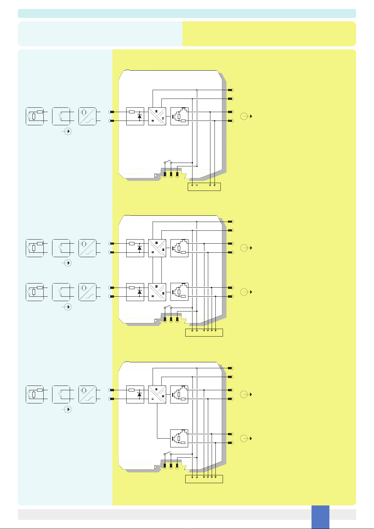
D5038 series can accept on input connections switches or proximity detectors (EN60947-5-6, NAMUR). The output port can assume two different impedance values (RL or RH) or it can
open completely. The module output repeats the input state according to the following correspondence: low input state -> RL, high input state -> RH. Alternatively, the output can be
configured to invert the input state. In both cases, the output opens and the fault LED turns on if any fault (open or short circuit) occurs at the corresponding input.
Presence of supply power and status of output (energized or de-energized), as well as integrity or fault condition of sensor and connecting line are displayed by signaling LEDs (green for
power, yellow for status and red for fault condition).
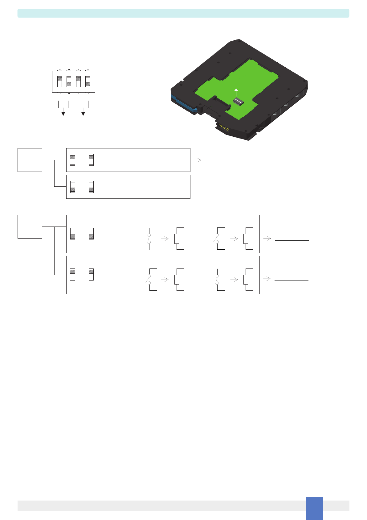
Note: use of voltage free electrical contacts with fault detection enabled (control equipment) requires, near the switch at the end of the line a R1=1 ktypical (470 to 2 krange)
resistor in series and a R2=10 ktypical (5 kto 15 krange) resistor in parallel to the contacts in order to allow the fault detection circuit to distinguish between a condition of contact
close/open and a line open/short circuit fault.
Installation
D5038 series is switch/proximity repeater housed in a plastic enclosure suitable for installation on EN/IEC60715 TH 35 DIN-Rail, with or without Power Bus or on customized Termination
Board. D5038 series can be mounted with any orientation over the entire ambient temperature range.
Electrical connections are accommodated by polarized plug-in removable screw terminal blocks which can be plugged in/out into a powered unit without suffering or causing any damage
(for Zone 2 installations check the area to be nonhazardous before servicing). Connect only one individual conductor per each clamping point, use conductors up to 2.5 mm²
(13 AWG) and a torque value of 0.5‑0.6 Nm. Use only cables that are suitable for a temperature of at least 85°C.The wiring cables have to be proportionate in base to the current and
the length of the cable.
On the section “Function Diagram” and enclosure side a block diagram identifies all connections.
Intrinsically Safe conductors must be identified and segregated from non I.S. and wired in accordance to the relevant national/international installation standards (e.g. EN/IEC60079‑14
Electrical apparatus for explosive gas atmospheres ‑Part 14: Electrical installations in hazardous areas (other than mines)), make sure that conductors are well isolated from each other
and do not produce any unintentional connection. Isolation in accordance with EN/IEC 60079‑11 clause 6.3.13 is provided between non‑intrinsically safe circuits and intrinsically safe
circuits.
The enclosure provides, according to EN60529, an IP20 minimum degree of protection (or similar to NEMA Standard 250 type 1). The equipment shall only be used in an area of at least
pollution degree 2, as defined in IEC 60664-1. When installed in EU Zone 2, the unit shall be installed in an enclosure that provides a minimum ingress protection of IP54 in accordance
with IEC 60079-0. When installed in a Class I, Zone 2 Hazardous Location, the unit shall be mounted in a supplemental AEx or Ex enclosure that provides a degree of protection not less
than IP54 in accordance with UL/CSA 60079-0. When installed in a Class I, Division 2 Hazardous Location, the unit shall be mounted in a supplemental enclosure that provides a degree
of protection not less than IP54. The enclosure must have a door or cover accessible only by the use of a tool. The end user is responsible to ensure that the operating temperature of
the module is not exceeded in the end use application.
Units must be protected against dirt, dust, extreme mechanical (e.g. vibration, impact and shock) and thermal stress, and casual contacts. If enclosure needs to be cleaned use only a
cloth lightly moistened by a mixture of detergent in water.
Electrostatic Hazard: to avoid electrostatic hazard, the enclosure of D5038 series must be cleaned only with a damp or antistatic cloth.
Any penetration of cleaning liquid must be avoided to prevent damage to the unit.
Any unauthorized modification must be avoided.
D5038 series must be connected to SELV or PELV supplies.
All circuits connected to D5038 series must comply with the overvoltage category II (or better) according to EN/IEC60664‑1.
Start-up
Before powering the unit check that all wires are properly connected, particularly supply conductors and their polarity, input and output wires, also check that Intrinsically Safe conductors
and cable trays are segregated (no direct contacts with other non I.S. conductors) and identified either by color coding, preferably blue, or by marking. Check conductors for exposed
wires that could touch each other causing dangerous unwanted shorts. Turn on power, the “power on” green led must be lit, status and fault led on each channel must be in accordance
with condition of the corresponding input line. If possible close and open input lines one at time checking the corresponding status and fault leds condition as well as output to be correct.

D5038 - I.S. SIL3 Line-Fault Transp. Switch/Prox. RepeaterG.M. International ISM0427-1 7
Configuration
ON
A configuration DIP switch is located on component side of PCB. This switch allows the configuration of input/output relationship, fault detection functions and operating mode.
Configuration of channel 2 is relevant only for D5038D*.
Line fault
detection
Dip switch factory settings.
Switches 1 and 3 are ON, switches 2 and 4 are OFF
1234
ON
ON OFF ON OFF
CH1 CH2
OFF
1
CH1
Enabled
(proximity sensor or switch with end of
line resistors, output opens in fault condition)
OFF
3
CH2
1
CH1
ON
3
CH2
ON
IN / OUT
operation Direct
function
OutputInput Output Input
open
or
closed RL RH
Reverse
function
OutputInputOutputInput
open
or
closed
RL RH
2
CH1
ON
4
CH2
ON
OFF
2
CH1
OFF
4
CH2
Disabled
(switch / proximity sensor)
For SIL application
For SIL application
For SIL application
This manual suits for next models
14
Table of contents
Other GMI Repeater manuals