DELEX DSI ES8302 Dual Arm Owner's manual

ES8302 Dual Arm
BARRIER ARM OPTICAL TURNSTILE
INSTALLATION AND OPERATION
INSTRUCTIONS


3
DESIGNED SECURITY INC
800-272-3555 www.dsigo.com
1402 Hawthorne Street Bastrop, Texas 78602 Fax 512 321 9181 Email: [email protected]
INS8302
CUSTOM NOTES


5
DESIGNED SECURITY INC
800-272-3555 www.dsigo.com
1402 Hawthorne Street Bastrop, Texas 78602 Fax 512 321 9181 Email: [email protected]
INS8302
SITE PREPARATION


7
DESIGNED SECURITY INC
800-272-3555 www.dsigo.com
1402 Hawthorne Street Bastrop, Texas 78602 Fax 512 321 9181 Email: [email protected]
INS8302
Refer to LANE PLACEMENT ERGONOMICS in the Appendix for information
regarding planning considerations which can maximize efficient traffic flow and
minimize nuisance alarms. Taking into consideration any installation from the
perspective of providing access control while minimizing the impact on the user’s
daily routine may allow security goals to be met more effectively.
PRE-INSTALLATION REQUIREMENTS
Conduit or other cableway:
1. From Access Control System to Each Lane’s Electronics for Input and Output connections.
2. From each Lane’s Electronics Side to opposite Arm for Motor and Encoder control cabling.
Mounting Anchors or Floor Plate:
A solid, stable mounting point for each bollard is necessary to maintain proper optical alignment.
Refer to information included for Specifications, and Layout, Squaring, and Leveling techniques.
See Base Plate Template or Dimensional drawing for access and mounting detail
PRE-INSTALLATION CONSIDERATIONS
The DSI Barrier Arm Optical Turnstile, although “high-tech”, is really a very straight-forward
installation when a little time is taken to prepare before you begin.
You may choose to take the time now to read and understand the installation and operation instructions
in order to gain an understanding of what the system does and what is required from you to install your
system. Experienced installers will find in this manual everything needed for trouble-free installation.
We are available to assist you by calling 800 272 3555 for Customer Support.
Treat the units as you would any fine furniture or delicate instrument. Keep them out of harsh
environments. Do not store or install them where they will be exposed to inclement weather, or
extremes of humidity, dust, or temperature. This will insure that they will keep their appearance and
functionality for many years to come.
When installing the wiring, be certain to strain-relief the cables to some hard point in the bollard and
leave enough service loop on each cable for any future repairs, component removal or upgrade. In
other words, take the time to route your wires in such a way that they will not be damaged, or in the
way, should the unit require servicing in the future.
Precautions should be taken to properly ground the units to a known “Earth Ground”, during the
mounting process, to prevent any ESD (electro-static discharge) damage to the electronics during
installation and operation.


9
DESIGNED SECURITY INC
800-272-3555 www.dsigo.com
1402 Hawthorne Street Bastrop, Texas 78602 Fax 512 321 9181 Email: [email protected]
INS8302
INSTALLATION

11
DESIGNED SECURITY INC
800-272-3555 www.dsigo.com
1402 Hawthorne Street Bastrop, Texas 78602 Fax 512 321 9181 Email: [email protected]
INS8302
INITIAL LAYOUT
Placement :
The bollards are designed to be placed in a parallel arrangement, not to exceed 48 inches between
bollards.
Spacing of 36” between bollards is our standard.
(Custom ordered lane spacing may differ from standard)
Mounting should leave a 2” gap between extended arms.
Verify the design specification for each lane prior to attachment. Refer to architectural plans, or set
the bollards up in proper order, with arms extended to determine appropriate spacing.
Ergonomics :
The number of lanes required is determined based upon the peak traffic volume and available
space. Contact the DSI Sales team for additional information.
The placement of the lanes should compliment the natural flow of traffic and not impede the flow any
more than necessary to achieve access control goals.
Care should be taken in placing the bollards to ensure that the user may easily access the Reader
System* (I.E.: Mag. Card, Proximity, Biometric, etc. [*provided by installer/integrator]) while
maintaining a reasonable flow of pedestrian traffic. (Readers may be pre-installed on some
applications) If you have any questions regarding Reader mounting, contact the DSI Support team.
Function :
For technical and aesthetic reasons it is very important to insure that the bollards are installed level
and plumb (horizontal and vertical), and in alignment with one another (parallel). Obviously the
installation will look better, and more importantly it will make the setup and adjustment of the optical
sensors much easier. More about this will be covered in the “Leveling and Aligning” section.
Quality Installation :
Experienced installation crews have found how attention
to detail during layout, anchoring, and performing the
leveling techniques will save valuable time and prevent having to spend much more time
later correcting optical alignment issues.
Verify the surface you are installing upon is not bowed or crowned. Shim Bollard to compensate for
uneven surfaces.
HORIZONTAL
VERTICAL
12
DESIGNED SECURITY INC
800-272-3555 www.dsigo.com
1402 Hawthorne Street Bastrop, Texas 78602 Fax 512 321 9181 Email: [email protected]
INS8302
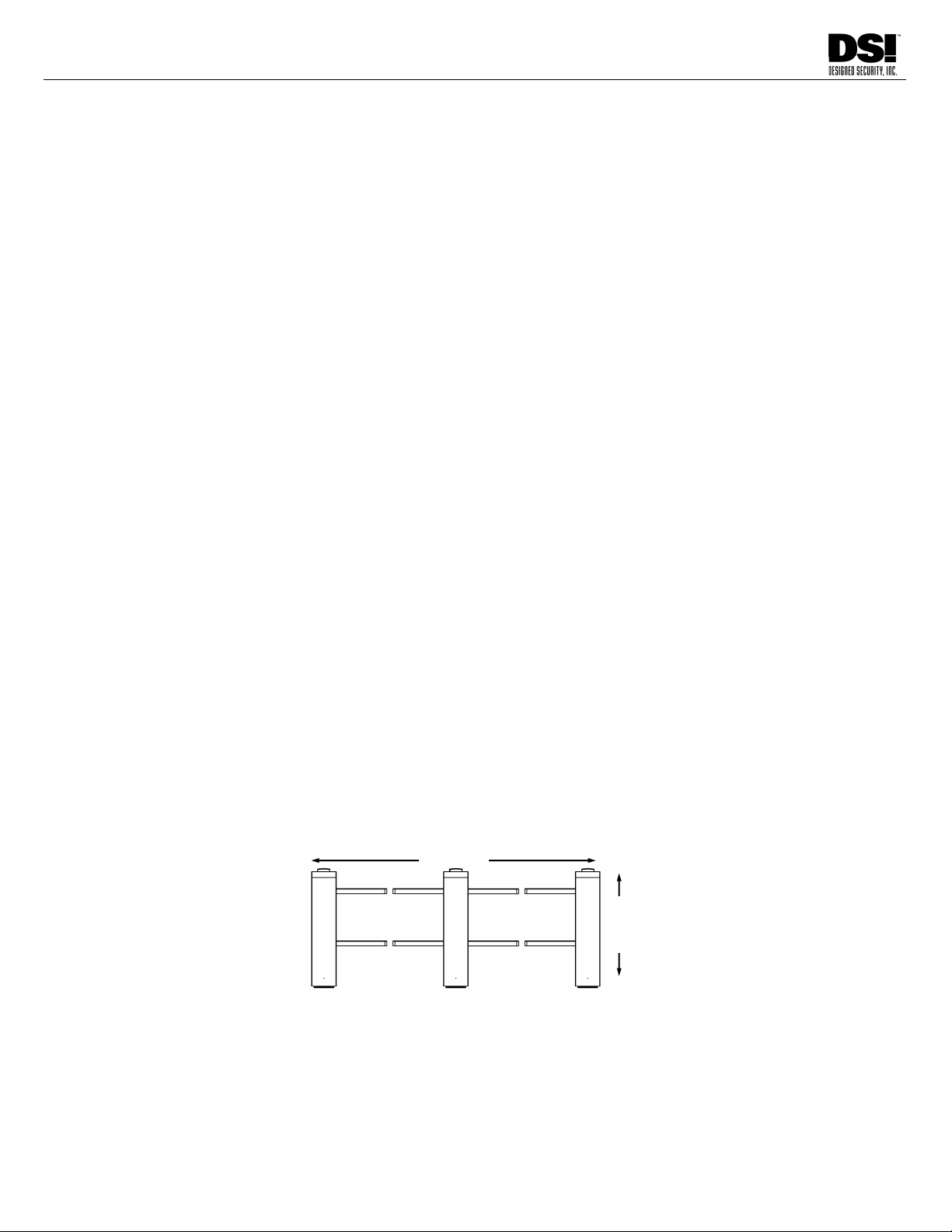
BOLLARD ORIENTATION
SECURE (EXIT)/UN-SECURE (ENTRY) SIDES—
DEFINED
In the above illustration the orientation of the bollards is shown to help installers understand the proper
placement of the Turnstiles in reference to the direction of traffic.
When entering the lane from the Un-Secure side, or Entrance Side, the Electronics Package for that
lane will be located, facing into the lane, in the bollard on the right.
NOTE: Be certain of this orientation prior to bolting the
bollard to the surface and running cables!
ENTRANCE SIDE
(UNSECURE)
ELECTRONICS LOCATION
Secure Side End
SECURE SIDE
13
DESIGNED SECURITY INC
800-272-3555 www.dsigo.com
1402 Hawthorne Street Bastrop, Texas 78602 Fax 512 321 9181 Email: [email protected]
INS8302
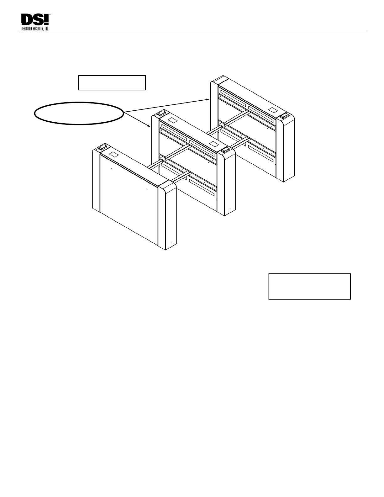
PANEL REMOVAL STEPS
Insert “T-Handle” Hex-key wrench into small hole near the top, side edge of panel.
Turn 3/4 turn Counter-Clockwise to release latch.
Repeat above steps for other small hole at opposite side of panel. Be ready to catch
panel.
Tilt panel away from the Bollard, then lift up to remove from lower pins. Use wrench to
get tilt-out started if necessary, by applying slight pressure down on wrench and
pulling, simultaneously. (minimal force)
Place removed panel in safe location. Take care to avoid damaging finish or creating
a hazard to pedestrian traffic.
PANEL INSTALLATION STEPS
Place panel on Hinge Points.
Tilt into place in Bollard.
Insert “T-Handle” Hex-key wrench into small hole near the top, side edge of panel.
Turn 3/4 turn Clockwise to latch.
Repeat for other small hole on opposite side of panel
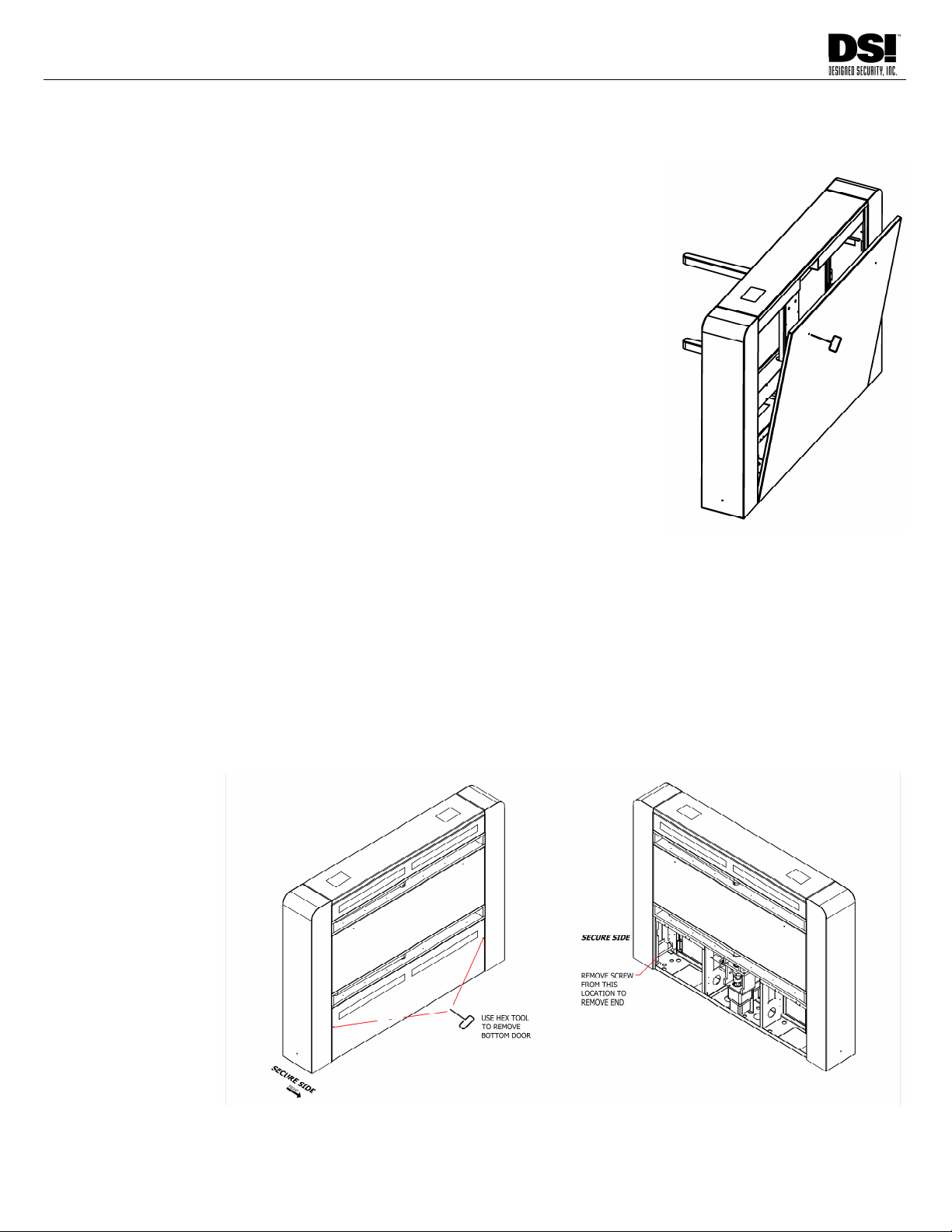
BOLLARD INTERNAL ACCESS

14
DESIGNED SECURITY INC
800-272-3555 www.dsigo.com
1402 Hawthorne Street Bastrop, Texas 78602 Fax 512 321 9181 Email: [email protected]
INS8302
LAYOUT AND MOUNTING
BOLLARD LAYOUT
Using a chalk line, or equivalent method, lay out the bollard arrangement. Bollard’s positions should be parallel and
square with each other.
Verify the “on centers” measurement to accommodate the bollard width and clearance for barrier arm operation prior to
setting anchors or drilling for conduit.
After going over the details of the installation with the architect or designer and you have determined planned
spacing and orientation of the system, you may have some questions regarding how to lay out the array of bollards
with the most accuracy in regard to alignment.
Here are two alignment tips which may be helpful:
Tip 1- Determining a “Right Angle” for alignment.
Without getting into a lot of math, there is a simple way to build a Right-Angle
Triangle by using sides of 3', 4' and 5'.
This method is based upon a geometric Theorem [a² + b² = c²]. Using this you
can calculate the length of the long side (C) of any right-angle triangle based
upon the known length of the other two sides.
Use this device to verify alignment by referencing a chalk line on the
floor.
Tip 2 - Alignment Check
Once you have established a known right-angle to the initial chalk-line, you will
want to verify that each bollard is aligned to the adjacent bollard.
You may do this by choosing a point on each end of a bollard, (for instance the
center of a mounting hole or a corner of a pedestal), you can measure in an “X”
pattern from one point to it’s opposite in the “X”.
When the bollards are the correct distance apart and both lengths of the “X” are
equal, the bollards are in alignment.
VERTICAL ALIGNMENT
Check level of the bollards vertically using a plumb or spirit level, use shims to make final
adjustments.
LEVEL
Level the bollards horizontally using a straight edge and/or a spirit level that will span two or three bollards at once.
ANCHORS
Use appropriate anchors for the mounting surface. Tighten securely to prevent any movement of the bollard.
Some custom models may have special mounting requirements. Additional information will have been provided when
necessary.
A C
B
BOLLARD
CHALK LINE
BOLLARD
BOLLARD
15
DESIGNED SECURITY INC
800-272-3555 www.dsigo.com
1402 Hawthorne Street Bastrop, Texas 78602 Fax 512 321 9181 Email: [email protected]
INS8302
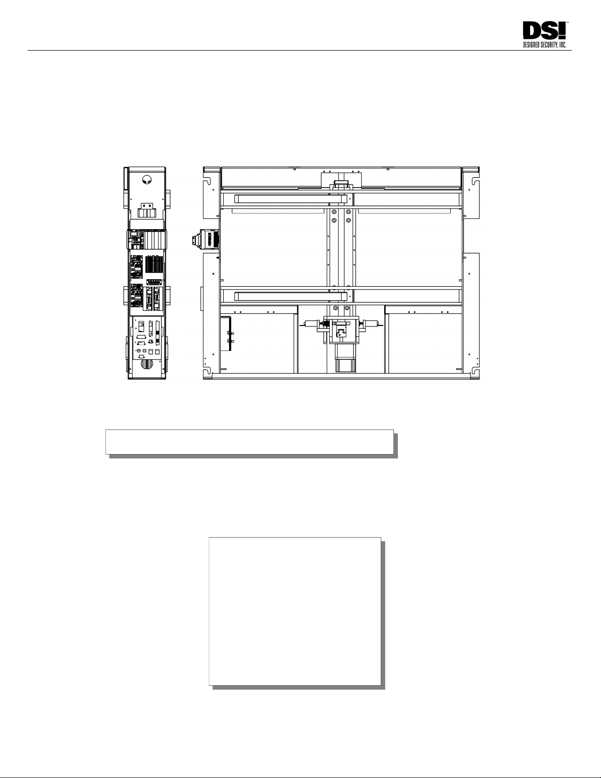
COMPONENT LOCATION
ENCODER
BARRIER ARM
D SENSORS C SENSORS
B & A SENSORS
MOTOR
ELECTRONICS
PACKAGE
MOUNTING
POINTS &
CABLE ACCESS
MOUNTING
POINTS &
CABLE ACCESS
END VIEW B-SIDE SHOWN
The A-Side of each Bollard will
have either;
A Motor/Arm Assembly
and Reflectors, or
Will be blank if it is on the
Right-most end of a set of
lanes when viewed from the
Entrance (Un-secure) side.
BARRIER ARM
16
DESIGNED SECURITY INC
800-272-3555 www.dsigo.com
1402 Hawthorne Street Bastrop, Texas 78602 Fax 512 321 9181 Email: [email protected]
INS8302
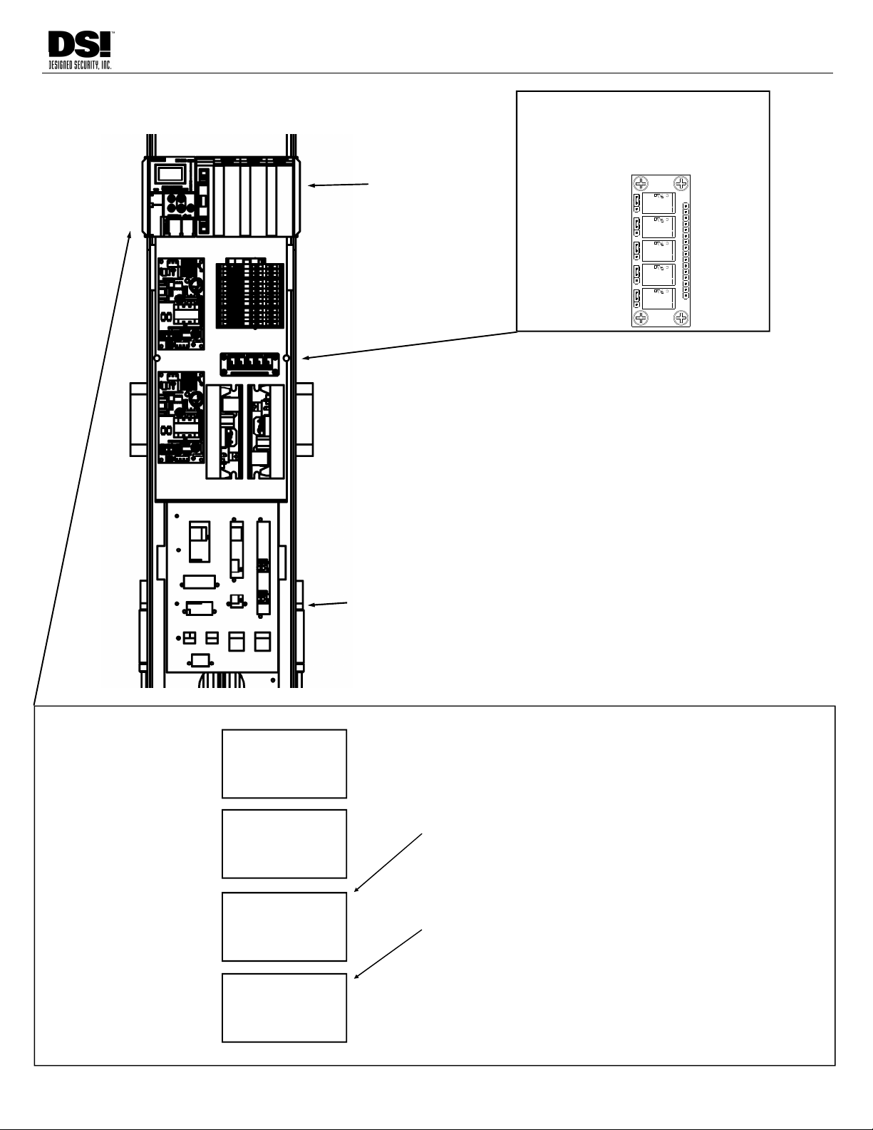
ELECTRONICS PACKAGE
BRIDGE PANEL
PLC
CONTROLLER
N/O OR N/C OUTPUT JUMPER
JUMPER LOCATED BESIDE EACH OUTPUT
RELAY MAY BE CONFIGURED FOR N/O OR
N/C OPERATION (DEFAULT IS N/O)
U10108H
REV0 COMP
BLC052102
TQ2-5V
ATQ202
NAIS
JAPAN
K5
SA
DSI
NAIS
K3
TQ2-5V
TQ2-5V
NAIS
ATQ202
NAIS
J5
U
JAPAN
10108H
J4
SA
K4
ATQ202
U10108H
J3
JAPAN
SA
JAPAN
TQ2-5V
ATQ202
NAIS
TQ2-5V
ATQ202
JAPAN
J2
10108HU
K2K1
SA
831 RELAY
U10108H
J1
SA
GATE FORCED
BYPASS
VALID
PASSAGE
TIMEOUT
ALARM
Move Jumper to
cover center and
lower pins for
N/C Output.
Default-Jumper
covers upper and
center pins for
N/O Output
SET TRIMMERS
(setting of “10” = 1 second)
To reach top menu press “M” key 3 times .
Use down arrow to highlight “3. Trimmers”. Press “Return”
Display will show “TRM0 Direct”. This is the Card Access Delay.
Use Left-Right Button to set Increment Value
Use Up and Down Buttons to change Current setting value
To move to next setting press “Return”
Display will show “TRM1 Direct”. This is the Auto Reset Time.
Use up arrow to increase value from “0” to “50”.
To return to “TRM0” press “Return” 7 times
To return to top menu press “M” key.
1.DeviceMode
2.ErrorClr
3.Trimmer
4.I/O TEST
TRMO Direct
50
L 300
1
TRM1 Direct
50
L 300
1
Project Name
GB030000
Start Screen
Version #
Top Menu
Trimmer 0 Card Access Dly
Current (default 50 = 5 sec)
Max Limit (300=30 sec)
Increment
Trimmer 1 Auto Reset Time
Current
Maximum
Increment
BA120000

17
DESIGNED SECURITY INC
800-272-3555 www.dsigo.com
1402 Hawthorne Street Bastrop, Texas 78602 Fax 512 321 9181 Email: [email protected]
INS8302
COMPONENT DESCRIPTION
Electronics Package
The Electronics are found in the right-hand pedestal as seen when facing the B-Side of the
bollard. (A-side holds the #2 Motor and reflectors for the lane.)
The Motor Controllers control the local arm and the remote arm. These are mounted in the
upper left-hand corner of the Electronics Package.
The PLC (Programmable Logic Controller) is the Module mounted on the DIN Rail and below
the Motor Controller(s). The PLC controls the arms by reading the Encoder position information
and communicating arm movement information to the Motor Controllers in response to PLC
inputs.
Sensors
The C1 & 2 Sensors are used to detect objects present in the arm path on the un-secure side of
the lane. If something is blocking these beams, the arms will not move to allow a user to exit
from the secure side (although the arms may always be pushed open in an emergency).
The D1 & 2 Sensors work similarly for users exiting from the secure side (IE: blocking this beam
will prevent the arms from moving) and, in addition these sensors will detect the presence of an
exiting user, when in “Free Exit” mode, and tell the PLC to move the arms to allow egress.
PLC Controller
The PLC (Programmable Logic Controller) is made up of several modules. All Inputs terminate
here and all Outputs originate here. The operating software runs on the PLC.
Wall and Bridge Connection Panels
The Wall is a panel located beside the Motor Controllers, on the left side of the Electronics
Package. All wiring for the lane’s local components goes through the Wall panel; including
Motor 1; Encoder 1; optional Lock Solenoid; and all Sensor connections.
The Bridge is a hinged panel located in front of the Electronics Module. All Input and Output
wiring and Remote; Motor 2, Encoder 2, optional Lock Solenoid, and Graphic Array cabling
terminates on the Bridge.
Additional detail regarding the Bridge panel and connectors is found in the Wiring section.
18
DESIGNED SECURITY INC
800-272-3555 www.dsigo.com
1402 Hawthorne Street Bastrop, Texas 78602 Fax 512 321 9181 Email: [email protected]
INS8302
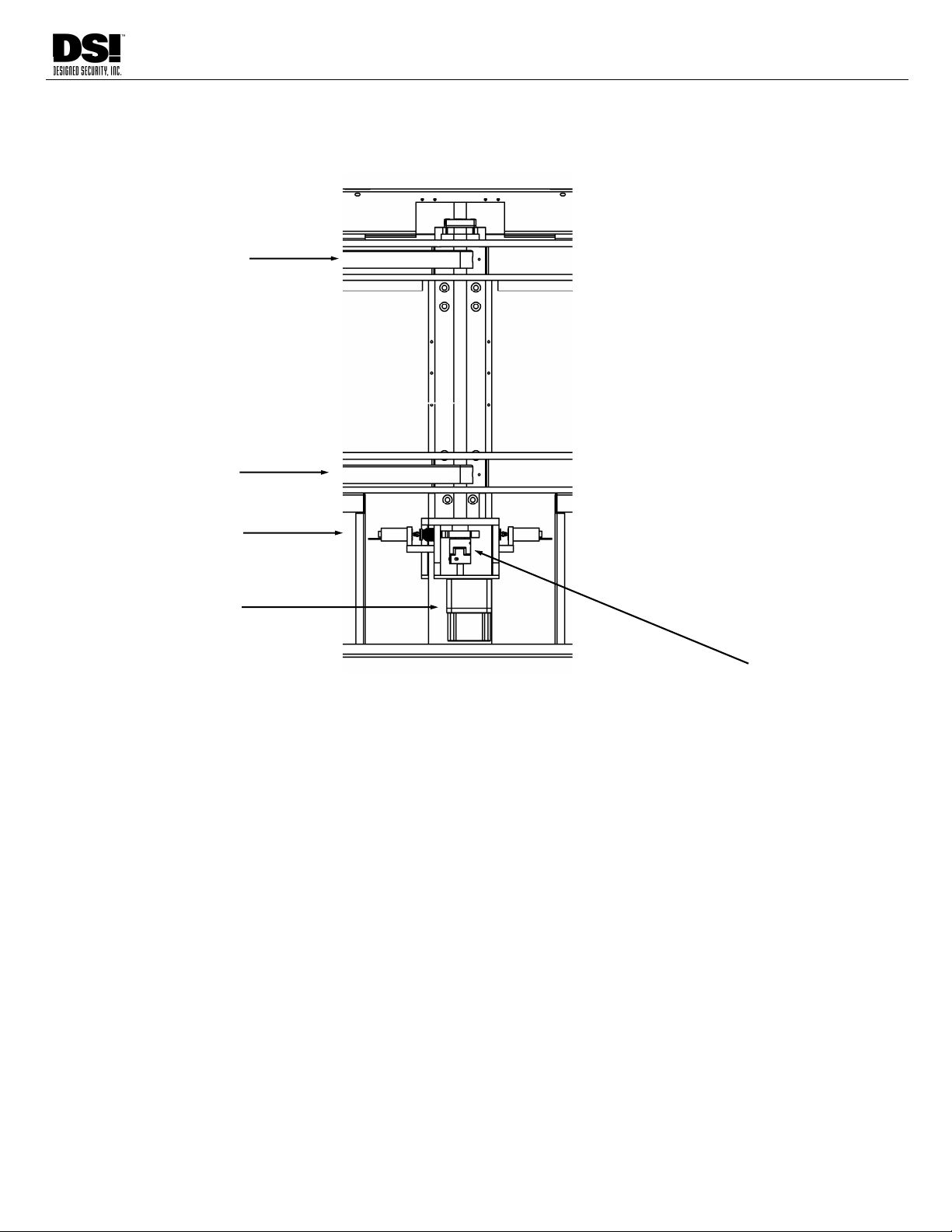
BARRIER ARM DRIVE ASSEMBLY
The Motor/Arm Assembly is the center section of the bollard, located between the two pedestals.
Located above the Barrier Arm housing is the Encoder. This is a very sensitive encoder used to detect
Barrier Arm position and provide this information to the Indexer. It is attached to the end of the shaft
that drives the Arm.
Below the Encoder is the Barrier Arm. Located on the same shaft.
(Units with optional Locking Arm will have Locking Solenoid hardware mounted on this shaft.)
This shaft goes into a shaft Coupler that allows quick removal of the Motor/Gearbox assembly for
maintenance and repair.
Beneath the Coupler is the Motor/Gearbox Assembly that drives the Barrier Arm.
Below the Arm Housing will be located either the B & A Sensors (below the Motor 1) or the B & A
Retro-reflectors (below the Motor 2). These are the sensor beams that detect direction of travel,
tailgating violations, and passage-complete for valid users.
ENCODER
BARRIER ARM
COUPLER
MOTOR/GEARBOX
ASSEMBLY
“B” & “A” SENSORS
LOCKING ARM
SOLENOID
(optional)
BARRIER ARM
WIRING

20
DESIGNED SECURITY INC
800-272-3555 www.dsigo.com
1402 Hawthorne Street Bastrop, Texas 78602 Fax 512 321 9181 Email: [email protected]
INS8302
WIRING
CABLE ROUTING
The Motor 2 and Encoder 2 cables must be routed between the “A” and “B” Sides of each
lane. (15 ft. cables included)
Optional Locking Arm: Additional Locking Solenoid cable is required to be pulled along with the standard
Motor 2 and Encoder 2 control cables.
If you are installing multiple lanes, you may want to use the next lane’s cable as reference
when reconnecting the cable to the connector to assure correct wire placement. Reference
wire color/pin-out information in this document.
Begin wiring from the Right-most bollard when facing from the Entrance (un-secure) side.
This bollard should have the Electronics Package in the side facing into the lane.
Leave adequate service loop in cables. Route cables neatly in pedestal.
Check conduit or cableway for airflow using a strip of tissue paper. If airflow is detected,
use paper or foam material to block airflow through conduit access hole. Airflow through
chassis may result in rapid dust accumulation on sensor optics which can lead to false alarms
and frequent cleaning requirements.
Power Cable must be of sufficient Gauge to provide 24VDC under load, measured at the
Power Input Connector. (See Power Wire Gauge Calculator in Appendix)
CABLE TERMINATION
Use the included WAGO™ tool to
remove and connect the wires on
each of the WAGO™ connectors.
Photo shows WAGO™ tool in use.
Hook over edge and press tab into
connector to release spring holding
each wire.
Table of contents
Other DELEX Turnstile manuals

Popular Turnstile manuals by other brands

Detex
Detex DSI ES9000-48 Assembly, installation and operation instructions

Rise
Rise RTF installation manual

PERCo
PERCo TTD-12A Assembly and operation manual

Alvarado
Alvarado SUPERVISOR 3000 user guide

Magnetic Autocontrol
Magnetic Autocontrol MPS-122 operating instructions

CAME
CAME TWISTER LIGHT PSBPS07N installation manual


