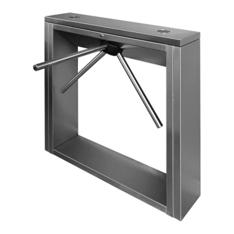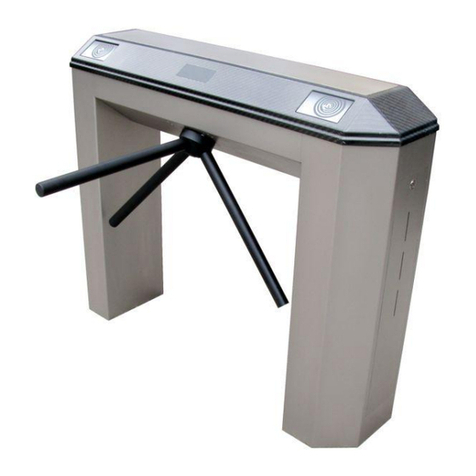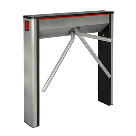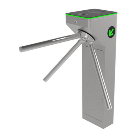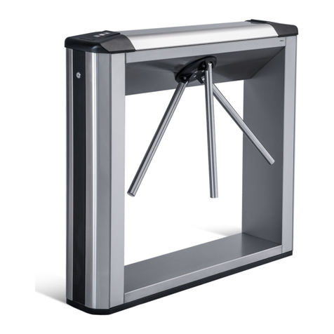
TTD-12A Motorized Box Tripod Turnstile
1
CONTENTS
1APPLICATION .......................................................................................................................2
2OPERATING CONDITIONS ..................................................................................................2
3TECHNICAL SPECIFICATIONS ............................................................................................3
4DELIVERY SET .....................................................................................................................4
4.1 Standard delivery set....................................................................................................... 4
4.2 Additional equipment supplied on request ....................................................................... 5
5DESIGN AND OPERATION................................................................................................... 5
5.1 Main features................................................................................................................... 5
5.2 Design ............................................................................................................................. 6
5.2.1 Main housing............................................................................................................7
5.2.2 Side modules ...........................................................................................................7
5.2.3 Indication blocks.......................................................................................................7
5.2.4 RC-panel..................................................................................................................8
5.2.5 Interface board.........................................................................................................9
5.2.6 Control signals .......................................................................................................11
5.2.7 Control modes........................................................................................................12
5.2.8 Turnstile operation algorithm .................................................................................. 13
5.3 Operation contingencies and response.......................................................................... 13
5.4 Control devices of the turnstile....................................................................................... 15
5.4.1 RC-panel connection.............................................................................................. 15
5.4.2 Fire Alarm emergency unblocking device ............................................................... 16
5.4.3 Control of the turnstile in ACS ................................................................................ 16
5.5 Additional devices connectable to the turnstile .............................................................. 17
5.5.1 Relay outputs .........................................................................................................17
5.5.2 Intrusion detector and siren .................................................................................... 18
5.5.3 Remote indicators ..................................................................................................18
5.6 Operation contingencies and response.......................................................................... 19
6MARKING AND PACKAGING ............................................................................................. 19
7SAFETY REQUIREMENTS ................................................................................................. 20
7.1 Installation safety requirements ..................................................................................... 20
7.2 Operation safety requirements....................................................................................... 20
8INSTALLATION ...................................................................................................................20
8.1 Installation details .......................................................................................................... 20
8.2 Installation tools............................................................................................................. 21
8.3 Length of cables ............................................................................................................ 21
8.4 Connection layout of the turnstile and additional equipment .......................................... 22
8.5 Installation sequence..................................................................................................... 26
9OPERATION INSTRUCTIONS ............................................................................................ 30
9.1 Power-up....................................................................................................................... 30
9.2 Pulse control mode........................................................................................................ 30
9.3 Potential control mode................................................................................................... 31
9.4 Algorithm of the card capture reader operation.............................................................. 32
9.5 Removal and installation of the card reader container ................................................... 33
10 ACTIONS IN EMERGENCY ................................................................................................ 33
11 TROUBLESHOOTING.........................................................................................................33
12 MAINTENANCE................................................................................................................... 34
13 TRANSPORTATION AND STORAGE ................................................................................. 35
Appendix 1. Design of different types of turnstile side covers..................................................... 35
Appendix 2. Algorithm of issuing command at pulse control mode............................................. 38
Appendix 3. Algorithm of issuing command at potential control mode........................................ 39
Appendix 4. Configuring PERCo ACS controller for operation with the card capture reader....... 40
