Detex DSI ES9000-48 Owner's manual

ES9000-48”
BARRIER OPTICAL TURNSTILE
INSTALLATION AND OPERATION
INSTRUCTIONS


3
INS9000 220523
DESIGNED SECURITY INC.
1402 Hawthorne Street Bastrop, Texas 78602
800-272-3555
Fax 512 321 9181
www.dsigo.com
Email: dsi@dsigo.com
INTRODUCTION
Welcome to the DSI family! The DSI ES9000 Barrier Optical Turnstile, although “high-tech”, is really
a very straight-forward installation when a little time is taken to prepare before you begin.
You may choose to take the time now to read and understand the installation and operation instructions
in order to gain an understanding of what the system does and what is required from you to install your
system. Experienced installers will find in this manual everything needed for trouble-free installation.
We are available to assist you by calling 800 272 3555 for Customer Support.
Treat the units as you would any fine furniture or delicate instrument. Keep them out of harsh
environments. Do not store or install them where they will be exposed to inclement weather, or
extremes of humidity, dust, or temperature. This will insure that they will keep their appearance and
functionality for many years to come.
When installing the wiring, be certain to strain-relief the cables to some hard point in the pedestal
and leave enough service loop on each cable for any future repairs, component removal or upgrade.
In other words, take the time to route your wires in such a way that they will not be damaged, or in
the way, should the unit require servicing in the future.
Precautions should be taken to properly ground the units to a known “Earth Ground”, during the
mounting process, to prevent any ESD (electro-static discharge) damage to the electronics during
installation and operation.
Your product may include customizations not described in the main text of this manual. The next page
includes notes outlining these customizations.

4 INS9000 220523
DESIGNED SECURITY INC.
1402 Hawthorne Street Bastrop, Texas 78602
800-272-3555
Fax 512 321 9181
www.dsigo.com
Email: dsi@dsigo.com
CUSTOM NOTES
5
INS9000 220523
DESIGNED SECURITY INC.
1402 Hawthorne Street Bastrop, Texas 78602
800-272-3555
Fax 512 321 9181
www.dsigo.com
Email: dsi@dsigo.com
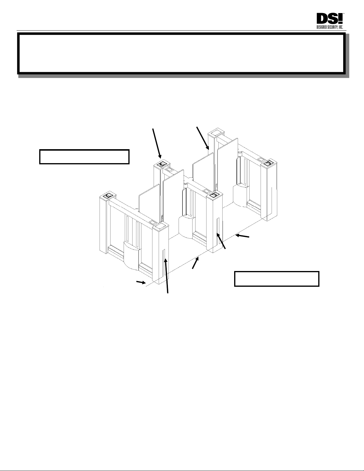
Precise placement and alignment of pedestals is critical for both functional and aesthetic
performance. Ensure pedestals are properly spaced and aligned square, level, and plumb.
Refer to the following diagram for expressions used in this section
LOCATING YOUR TURNSTILE SYSTEM
There are three key technical considerations for locating the turnstiles. Two fairly obvious, the other,
not as much.
The first obvious consideration is that a solid, stable mounting point for each pedestal is necessary to
maintain proper alignment. Select a location that is flat and level, minimizing crowns or bows that would
require pedestal shimming.
The second fairly obvious placement consideration is not to put turnstiles such that either vestibule is
too close to a perpendicular barrier such as a wall, door, or velvet rope. This can cause queueing
issues that will slow traffic and possibly leave users stranded in the lane waiting for traffic to clear.
Pedestals placed too close to walls may make cover removal difficult.
The not-so-obvious consideration concerns Free Exit applications. If the Exit side approach is too long,
users may be encouraged to achieve speeds such that they will get to the gate before it fully opens.
ENTRY/PUBLIC SIDE
EXIT/SECURE SIDE
PRIMARY/LOCAL
ELECTRONICS
REMOTE ELECTRONICS
EXIT
VESTIBULE
EXIT
VESTIBULE
ENTRY VESTIBULE
PRIMARY/LOCAL
ELECTRONICS
2 “B” WIRE GROUPS
1 “A” WIRE GROUP
1 “B” WIRE GROUP
1 “A” WIRE GROUP
ENTRY VESTIBULE
SITE PREPARATION

6 INS9000 220523
DESIGNED SECURITY INC.
1402 Hawthorne Street Bastrop, Texas 78602
800-272-3555
Fax 512 321 9181
www.dsigo.com
Email: dsi@dsigo.com
LAYOUT AND MOUNTING
PEDESTAL LAYOUT
Using a chalk line, or equivalent method, lay out the pedestal arrangement. Pedestal positions should be parallel and
square with each other.
PEDESTAL SPACING
Verify the “on centers” measurement to accommodate the pedestal width and clearance for barrier operation prior to
setting anchors or drilling for conduit.
Lanes are specified by open walkway space—typically 36”. The pedestals measure 8” wide, so, in this case, the on-
center measurement would be 44”
This spacing will maintain a minimum 3.5” between the extended gate panels.
After going over the details of the installation with the architect or designer and you have determined planned
spacing and orientation of the system, you may have some questions regarding how to lay out the array of
pedestals with the most accuracy in regard to alignment.
Here are two alignment tips which may be helpful:
Tip 1- Determining a “Right Angle” for alignment.
Without getting into a lot of math, there is a simple way to build a Right-Angle
Triangle by using sides of 3', 4' and 5'.
This method is based upon a geometric Theorem [a² + b² = c²]. Using this you
can calculate the length of the long side (C) of any right-angle triangle based
upon the known length of the other two sides.
Use this device to verify alignment by referencing a chalk line on the
floor.
Tip 2 - Alignment Check
Once you have established a known right-angle to the initial chalk-line, you will
want to verify that each pedestal will be aligned to the adjacent pedestal.
You may do this by choosing a point on each end of a pedestal mount, (for
instance the center of a mounting hole), you can measure in an “X” pattern from
one point to it’s opposite in the “X”.
When the pedestals are the correct distance apart and both lengths of the “X” are
equal, the pedestals are in alignment.
ANCHORS
Use appropriate anchor system for the mounting surface.
DSI recommends 1/2” diameter anchors
A C
B
PEDESTAL
CHALK LINE
PEDESTAL
PEDESTAL
7
INS9000 220523
DESIGNED SECURITY INC.
1402 Hawthorne Street Bastrop, Texas 78602
800-272-3555
Fax 512 321 9181
www.dsigo.com
Email: dsi@dsigo.com
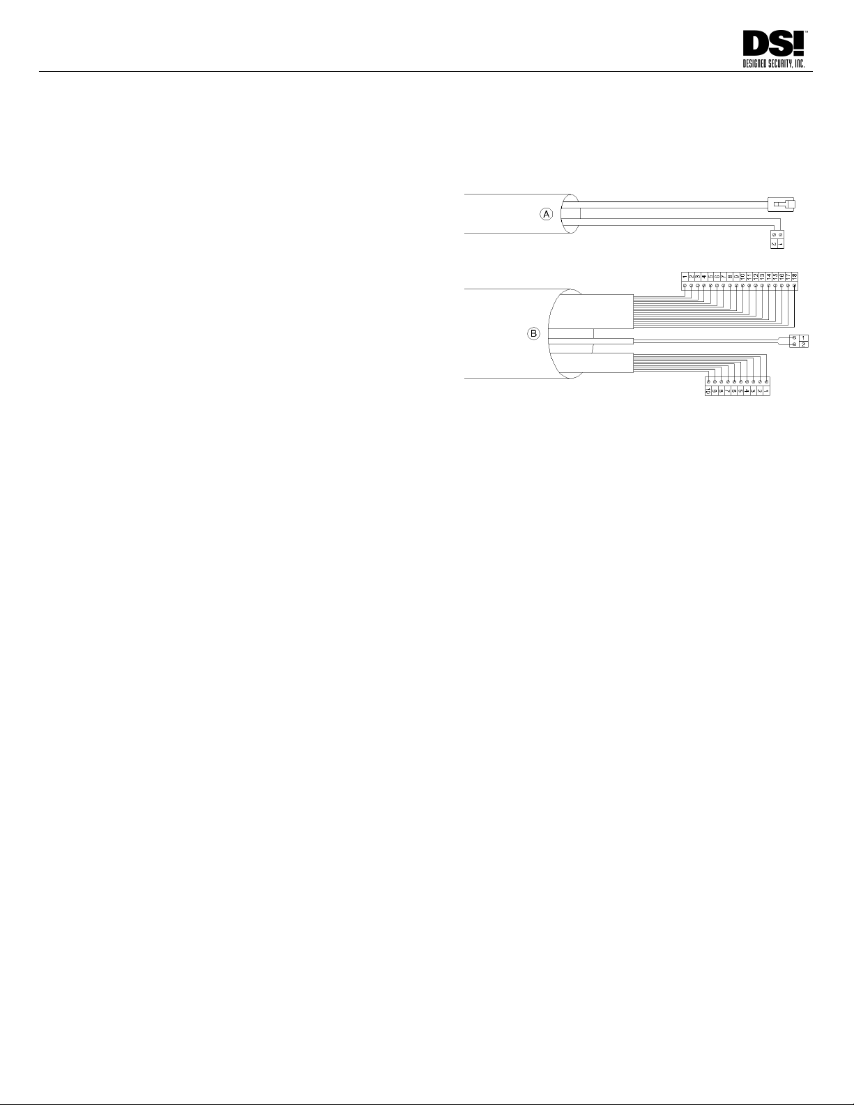
CONDUIT OR OTHER CABLEWAY PLACEMENT
The pedestals will be oriented so the Primary Electronics is located on the Secure side. The Conduit
should be located below this end of the pedestal. There are two wiring groups:
A. Lane Power and Lane Data from each Lane’s
Primary Electronics to opposite pedestal for
remote pedestal control cabling.
B. From Access Control System to Each Lane’s
Primary Electronics for Input, Output, and
Power connections.
See Base Plate Template or Dimensional drawing for access and mounting detail

8 INS9000 220523
DESIGNED SECURITY INC.
1402 Hawthorne Street Bastrop, Texas 78602
800-272-3555
Fax 512 321 9181
www.dsigo.com
Email: dsi@dsigo.com
BASE PLATE TEMPLATE
9
INS9000 220523
DESIGNED SECURITY INC.
1402 Hawthorne Street Bastrop, Texas 78602
800-272-3555
Fax 512 321 9181
www.dsigo.com
Email: dsi@dsigo.com
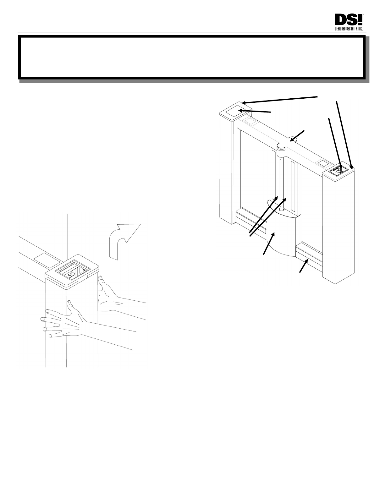
If site preparation is complete, you are ready to mount the
pedestals. The pedestal cladding is assembled with
fasteners hidden by acrylic covers. These covers are held
with magnetic strips and can be removed with a suction
cup. Due to characteristics of the magnetic strips used to
fasten the acrylics, each cover must be returned to its
original location and orientation. Each acrylic is labeled
and a corresponding label is found at its location. Return
removed acrylics to matching label location and
orientation.
To mount the pedestal to the floor, you will need to
remove the End Cover, Center Sensor Covers and Motor
Cover.
END REMOVAL STEPS
Remove Card Reader acrylic cover with suction cup.
Turn thumbscrew 1/4 turn CCW to unlatch.
While gripping sides of end with the palms of your hands, lift straight up
approximately 3/4” then pull away.
Do not lift by Solid Surface top.
Repeat for both ends.
CENTER SENSOR COVER REMOVAL STEPS
Remove acrylic sensor covers from center panels with suction cup.
Each cover is attached with 2 Philips-head truss bolts. Remove bolts.
Remove panels and set aside.
MOTOR COVER REMOVAL STEPS
Remove Center Sensor Cover as noted above. Remove 2 Philips-head truss bolts located toward top of cover.
Remove motor cover by lifting directly up approximately 1/2”.
Place removed covers in safe location. Take care to avoid damaging finish or creating a hazard to pedestrian traffic.
End Cover
Top Cover
Card Reader Acrylic
Motor Cover
Center Sensor Covers
Lower Sensor Cover
INSTALLATION

10 INS9000 220523
DESIGNED SECURITY INC.
1402 Hawthorne Street Bastrop, Texas 78602
800-272-3555
Fax 512 321 9181
www.dsigo.com
Email: dsi@dsigo.com
ANCHOR TO FLOOR
With pedestal mounting holes and conduit access
exposed, place pedestal on mounting point. Orient
pedestal such that Primary Electronics are located
toward the Secure Side. The right-most pedestal, when
viewed from the secure side will only have the Remote
Electronics located toward the Public side. Refer to
“Site Preparation”, Page 5 to verify these orientations.
Verify the surface you are installing upon is not bowed
or crowned. Use leveling bolts to level pedestal, then
shim pedestal to compensate for uneven surfaces.
Snug mounting fasteners, but do not fully tighten yet.
This will allow you to fine-tune the pedestal alignments.
INSTALL BARRIER PANELS
With pedestals attached to floor, next install the barrier
panels. The barrier shaft has two mounting holes.
Each mounting hole has a counterbore on one end.
Rotate the shaft to orient the mounting hole lengthwise
to the pedestal and counterbore toward the Secure
Side. The barrier panel clamp has visible screws on
one surface. Orient panel as shown with clamp screws
visible. If screws are not visible, you have the incorrect
panel for this location. This orientation will allow a
more cosmetic finish when viewed from the Public side.
Remove mounting bolts stored in threads of clamp, and
mount barrier panel to shaft by inserting mounting bolts
through shaft from counterbore side and thread back
into clamp. Tighten to 20 ft-lb.
SQUARE PEDESTALS
Check that pedestals are square to each other using
techniques outlined in Site Preparation, Page 6.
VERTICAL ALIGNMENT
Check level of the pedestals vertically using a plumb or
spirit level, use shims to make final adjustments.
LEVEL ELEVATION
Level the elevation of the pedestals using a straight edge and/or
a spirit level that will span two or three pedestals at once.
ANCHORS
Tighten securely to prevent any movement of the pedestal.
If you are ready to wire turnstiles, Skip to Wiring section. Otherwise, see next page for cover installation.
ADJACENT PEDESTAL SHOWN
Mounting Points
Barrier Panels
Leveling
Bolts
Primary
Electronics
Barrier
Mounting
Bolts
Visible
Screws
PUBLIC SIDE
SECURE SIDE
Earth
Ground

11
INS9000 220523
DESIGNED SECURITY INC.
1402 Hawthorne Street Bastrop, Texas 78602
800-272-3555
Fax 512 321 9181
www.dsigo.com
Email: dsi@dsigo.com
COVER INSTALLATION
When all covers are removed, some must be installed in a specific order. The following order accounts
for that sequence.
All fasteners should easily install using hand tools—PLEASE DO NOT USE POWER TOOLS.
LOWER SENSOR COVER
In the rare case the Lower Sensor Cover is removed, it can be reinstalled at any time.
Align cover approximately 1/2” above finish location.
Lower onto hook system.
Install 2 Truss Bolts in mounting holes under acrylic cover
Replace labeled acrylic cover to original location.
MOTOR COVER INSTALLATION
Align cover approximately 1/2” above finish location.
Lower onto hook system.
Install 2 Truss Bolts in top tabs to anchor cover.
CENTER SENSOR COVER INSTALLATION
Return cover to original location.
Align mounting holes.
Install 2 Truss Bolts in mounting holes.
Replace labeled acrylic cover to original location.
TOP COVER INSTALLATION
Return top cover to original location, noting orientation so Entry and Exit Displays are on correct ends.
Rounded center protrusions are a tight fit. Align precisely.
Plug in displays. Entry is 8-pin modular connector. Exit is 6-pin modular connector.
Lower onto pedestal.
END COVER INSTALLATION STEPS
Stand at end, grip both sides of end-panel and align straight onto pedestal, approximately 1”above finish location.
Lower end-panel onto hook system.
Rotate fastener 1/4 turn clockwise to latch.
Install card reader acrylic cover.


13
INS9000 220523
DESIGNED SECURITY INC.
1402 Hawthorne Street Bastrop, Texas 78602
800-272-3555
Fax 512 321 9181
www.dsigo.com
Email: dsi@dsigo.com
CABLE ROUTING
Route Input and Output cables from Access Control System (ACS) to each Primary Electronics,
located on Secure Side.
Route power cable from each 24VDC @ 4A power supply to each Primary Electronics. Power Cable
must be of sufficient Gauge to provide 24VDC under load, measured at the Power Input Connector.
(See Power Wire Gauge Calculator, Page 24)
The Lane Power and Lane Data cables must be routed between the Primary and Remote Electronics
of each lane. (20 ft. cables included).
The recommended installation is to have lane conduit under the Secure Side, Therefore, to route
cables to the Remote Electronics, remove Top Cover of remote pedestal to access the upper wiring
tray. Top Cover simply lifts off once both End Covers are removed. Unplug displays to fully remove
Use provided wire anchors to contain wires in tray. This will prevent wire damage when reinstalling
cover.
Leave adequate service loop in cables. Route cables neatly in pedestal.
Attach Earth Ground to provided locations.
Check conduit or cableway for airflow. If airflow is detected, block airflow through conduit access hole.
Airflow through chassis may result in rapid dust accumulation on sensor optics which can lead to false
alarms and frequent cleaning requirements.
TERMINATIONS
POWER CONNECTOR
Connect 4 Amp 24 Volt DC Power Supply to the “24VDC POWER INPUT” connector. Pin 1 is “+”, 2 is “-”.
See page 24 for Power Wire Gauge Calculator to determine proper gauge for your application.
ADJACENT PEDESTAL INTERCONNECTIONS
Plug Lane Power cable into LANE POWER connector.
Plug Lane Data cable into LANE DATA connector.
Once powered, Data Status LED on each Electronics will indicate Lane Data quality.
ON = Data Good.
OFF = No Connection - Cable not plugged in.
Flashing = Data corrupted – plug not fully seated; connector reterminated incorrectly; noisy cable path.
INPUT AND OUTPUT CONNECTIONS
Terminate all Input and Output wiring to Connectors (provided).
Input connector is inserted from bottom of board with screw-heads oriented toward backplate.
WARNING: Multiple lanes sharing a common Input Source (i.e. Fire Alarm) must be isolated through a unique
relay contact for each lane input. Wiring common inputs in parallel can cause damage to electronics.
Configure output jumpers for N/O or N/C operation.
J1 and J2 for Alarm Output.
J3 for Valid Exit Complete Output.
J4 for Valid Entry Complete Output.
J5 for Bypass Status Output.
WIRING
N/C OUTPUT - 2 to 3
N/O OUTPUT - 1 to 2
3
2
1
14 INS9000 220523
DESIGNED SECURITY INC.
1402 Hawthorne Street Bastrop, Texas 78602
800-272-3555
Fax 512 321 9181
www.dsigo.com
Email: dsi@dsigo.com
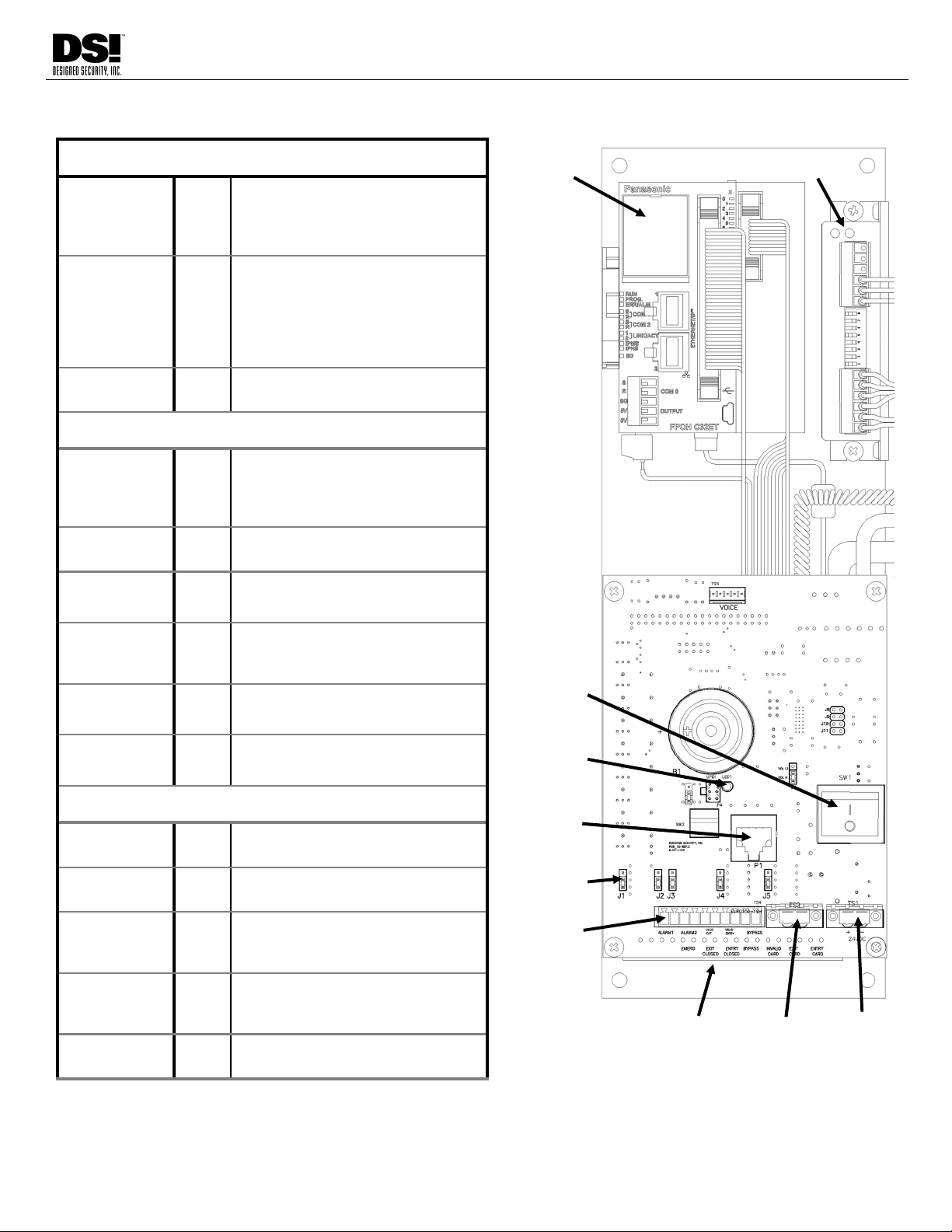
PRIMARY ELECTRONICS DETAIL
Inputs from Access Control System
Entry Valid
Card Read
1-2 Dry contact closure indicating valid
Entry card read
(Momentary Closure of .3 to .5
second recommended)
Exit Valid
Card Read
3-4 Dry contact closure indicating valid
Exit card read
(Momentary Closure of .3 to .5
second recommended)
Hold input for more than 20s for
Free Exit
Invalid Card 5-6 Dry contact closure when an invalid
card has been presented.
Inputs for Remote Control
Reset/Bypass 7-8 Dry contact closure to reset alarms
or to bypass the lane, stow the
barriers and allow unrestricted
traffic flow.
Entry Closed 9-10 Dry contact closure disables Entry
mode.
Exit Closed 11-12 Dry contact closure disables Exit
mode.
Emergency 13-14 Dry contact closure, moves
Barriers to Exit, activates alarm
graphics, and alarm relay output.
Reserved 15-16 Reserved for future use.
Reserved 17-18 Reserved for future use
Outputs for Remote Monitoring
Alarm 1-2 Indicates that unit is in Alarm
Mode.
Alarm 3-4 Indicates that unit is in Alarm
Mode.
Valid Exit 5-6 Indicates that an Exit passage was
completed. Closes for .3 sec when
triggered.
Valid Entry 7-8 Indicates that an Entry passage
was completed. Closes for .3 sec
when triggered.
Bypass 9-10 Indicates when unit is in Bypass
Mode.
Inputs
Outputs
Lane
Data
Lane
Power
24VDC
Power
N/O - N/C
Jumpers
PLC Motor Driver
Power
Switch
Data
Status
LED
WARNING: Multiple lanes sharing a common Input Source (i.e. Fire Alarm) must be isolated
15
INS9000 220523
DESIGNED SECURITY INC.
1402 Hawthorne Street Bastrop, Texas 78602
800-272-3555
Fax 512 321 9181
www.dsigo.com
Email: dsi@dsigo.com
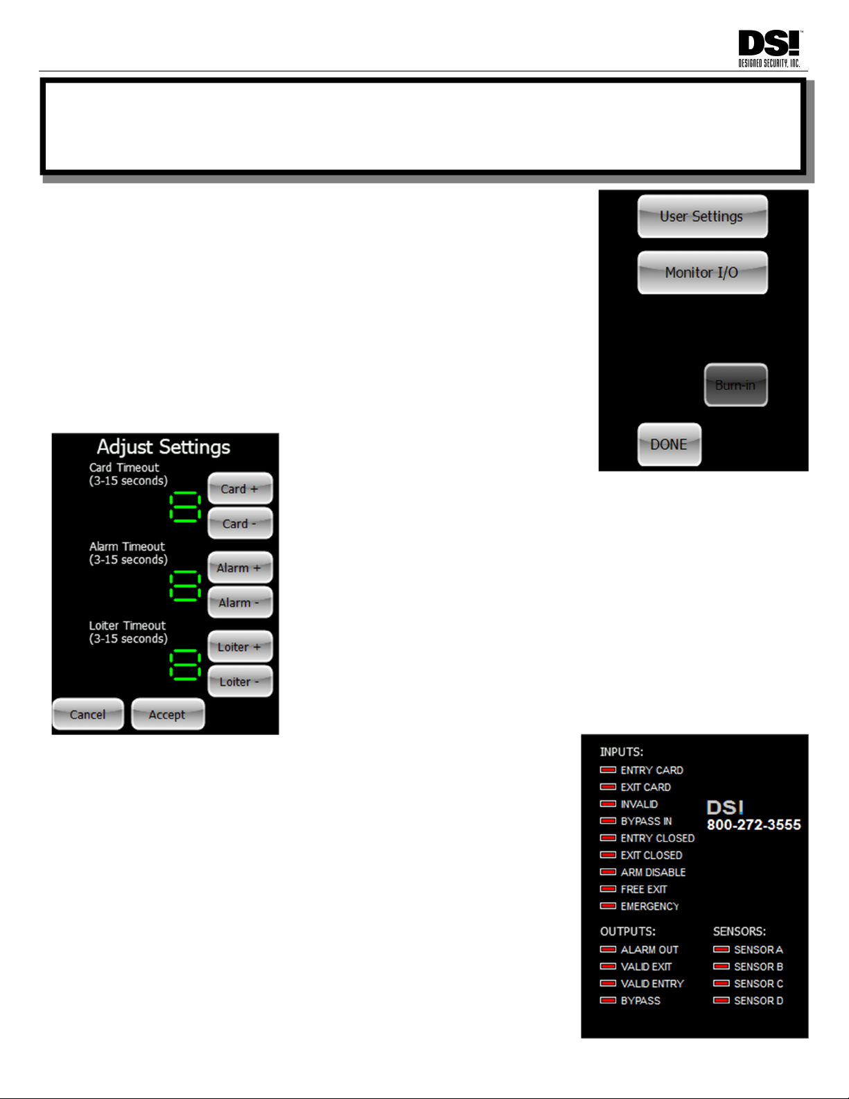
SETUP & OPERATION
Setup of the pedestal is accomplished via the LCD display located
on the Public side. Use a suction cup to remove acrylic cover, then
touch powered LCD. The main menu will display. User Settings al-
lows adjustment of internal timers, and Monitor I/O helps diagnose
connection issues by showing Inputs and Outputs in real time. Burn-
In is a factory function.
Tap Done to return to normal operation. Replace acrylic cover.
Tap the User Settings button to access the Timer Adjustments. As one
would expect, tap “+” for each timer to increase, and “-” to decrease.
Click Accept to save and return to main menu.
Card Timeout is the valid access grant time. It starts when valid card is
retrieved from the queue. System rearms at end of Timeout period.
Alarm Timeout is the minimum alarm duration. Many users with a latch-
ing device that monitors the Alarm Relay will set this 3s so the lane is
quickly available for next passage.
Loiter Timeout sets duration that a valid user can stand in lane after
crossing the center threshold.
Tap Monitor I/O to launch a diagnostic tool that monitors the In-
puts and Outputs. Red means the input is open/deactivated.
Green means the contact is closed/active. This is useful to verify
that the signals from the ACS are on the correct I/O pins. Green
on a Sensor Input indicates that channel is blocked. Sensor C is
a vestibule sensor on the Public Side. Sensor A is an anti-
tailgate sensor on the Public Side of the gate near center. Sen-
sor B is the Secure Side version of Sensor A. Sensor D is the
Secure Side vestibule sensor.
Arm Disable and Free Exit are legacy images that haven’t been
removed from this screen. The legacy Arm Disable feature was
almost never used, and Free Exit is now invoked by holding the
Exit Card input for 20 seconds or more.

16 INS9000 220523
DESIGNED SECURITY INC.
1402 Hawthorne Street Bastrop, Texas 78602
800-272-3555
Fax 512 321 9181
www.dsigo.com
Email: dsi@dsigo.com
COMPONENT LOCATION
ENCODER
BARRIER PANEL
D SENSORS C SENSORS
A SENSOR
GEARMOTOR
ELECTRONICS
PACKAGE
MOUNTING
POINTS &
CABLE ACCESS
MOUNTING
POINTS &
CABLE ACCESS
B SENSOR
COUPLER
LOCK
(OPTIONAL)
PLASTIC BUMPER PLASTIC BUMPER

17
INS9000 220523
DESIGNED SECURITY INC.
1402 Hawthorne Street Bastrop, Texas 78602
800-272-3555
Fax 512 321 9181
www.dsigo.com
Email: dsi@dsigo.com
COMPONENT DESCRIPTION
Electronics Package
The Primary Electronics are found in the end of the left pedestal of each lane when viewed from the Secure side.
The Remote Electronics are found in the left pedestal when viewed from the Public side.
The Motor Controllers control the local and remote barriers. These are mounted on each electronics panel,
immediately above and to the right of the electronics control board.
The PLC (Programmable Logic Controller) is the Module mounted on the DIN Rail at the top of the Primary
Electronics Package. The PLC controls the barriers by reading the Encoder position information and
communicating barrier movement information to the Motor Controllers in response to PLC inputs.
Sensors
The “C” Sensors are used to detect objects present in the barrier path on the Public side of the lane. If something
is blocking these beams, the barriers will not move to allow a user to exit from the secure side (although the barriers
may always be pushed open in an emergency).
The “D” Sensors work similarly for users exiting from the secure side (IE: blocking this beam will prevent the
barriers from moving in the Entry direction) additionally, when set for Free Exit, these sensors will detect the
presence of an exiting user and tell the PLC to move the barriers to allow egress.
On either side of the Barrier will be located the A & B Sensors or the A & B Transmitters. These are the sensor
beams that detect direction of travel, tailgating violations, and passage-complete for valid users.
Connection Panels
All Input and Output wiring, Power input, Lane Power and Lane Data terminate on the Primary
Control Board.
The Motor/Barrier Assembly is the center section of the pedestal.
Located above the Barrier is the Encoder. This is a very sensitive encoder used to detect Barrier
position and provide this information to the PLC. It is attached to the end of the shaft that drives the
Barrier Panel.
Below the Encoder is the Barrier Panel. Located on the same shaft.
Units with optional Locking will have Locking Solenoid hardware mounted on this shaft.
This shaft goes into a shaft Coupler that allows quick removal of the Motor/Gearbox assembly for
maintenance and repair.
Beneath the Coupler is the Motor/Gearbox Assembly that drives the Barrier.
18 INS9000 220523
DESIGNED SECURITY INC.
1402 Hawthorne Street Bastrop, Texas 78602
800-272-3555
Fax 512 321 9181
www.dsigo.com
Email: dsi@dsigo.com
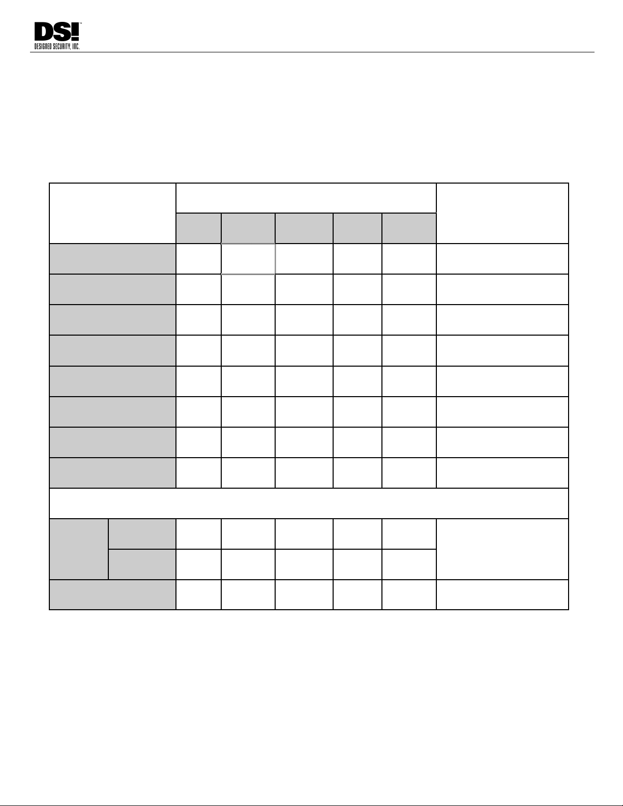
FINAL TESTING PROCEDURE
With all wiring and setup completed, turn on power switch. Barriers will slowly move toward the Public
side until they both come in contact with the Plastic Bumper on the Top Cover. They will then swing
180° toward the Secure side to verify a clear path. They will then return to the center position and be
ready for operation. Follow the table below to test basic functions. Apply the designated input, then
check for the indicated responses. Once finished, if you haven’t already, install all covers as indicated
on Page 11.
INPUTS
OUTPUTS BARRIER
POSITION
ALARM VALID
ENTRY
VALID
EXIT BYPASS AUDIBLE
ENTRY CARD O Entry direction for duration
of Card Access Time
EXIT CARD O Exit direction for duration of
Card Access Time
INVALID CARD O Centered/Armed
RESET/BYPASS O Entry direction
ENTRY CLOSED Center if no other activity
EXIT CLOSED Center if no other activity
FREE EXIT
(EXIT HELD 20s) Exit direction when “D”
Sensor is broken by user
EMERGENCY O Exit direction
BARRIER AND SENSOR STATES
FORCED
BARRIER
& PASSAGE O O BARRIERS WILL
PROVIDE RESISTANCE
AGAINST ATTEMPTS TO
FORCE PASSAGE
NO
PASSAGE
TAILGATE O O
19
INS9000 220523
DESIGNED SECURITY INC.
1402 Hawthorne Street Bastrop, Texas 78602
800-272-3555
Fax 512 321 9181
www.dsigo.com
Email: dsi@dsigo.com
GUIDELINES FOR EVERYDAY USE
(PROVIDE COPIES TO ALL TURNSTILE USERS)
Optical Turnstiles are provided for greater security in your workplace.
They help ensure that only authorized individuals will be allowed into the secure areas of your facility.
You may find daily use of Optical Turnstiles becomes routine as you follow these basic guidelines:
USER VALIDATION
“ID” for access control can be of many types, from card readers to biometric systems.
Please refer to instructions provided for reader operation by the manufacturer, or by your security director.
Look at display for LANE READY status, then
present ID to the Reader mounted on, or in, the
right-hand pedestal of the lane you are using. It
may beep to indicate your ID was read.
Listen for a BEEP after the ID has been
validated and/or watch the Display on the top of
the right-hand pedestal to indicate authorization.
Next Look for a PROCEED/BYPASS message to
indicate that you are now authorized to pass
through the lane. The barriers will
automatically swing out of the way allowing
passage.
CAUTION: AVOID TOUCHING THE BARRIER, except in an Emergency, otherwise AN ALARM MAY SOUND
MOVE THROUGH THE LANE PROMPTLY. Avoid stopping or moving backward, as this will trigger the alarm.
TIP: During passage through the lane, swinging items (purses, briefcases, etc.) could be interpreted by the
turnstile as a person tailgating you, or moving in the other direction, thus causing an alarm. To avoid delays
caused by false alarms, hold items high and close to your body, or at your side as you pass through the lane.
IF ALARM SOUNDS, exit the lane, STOP and wait for security personnel to respond.
Once through the lane, continue moving ahead to clear the lane for other users.
FREE EXIT MODE
Some turnstiles may be configured for “Free-Exit,” meaning there is no requirement to present ID when leaving the secured
area. Look for PROCEED/BYPASS graphic on the right-hand side of the lanes when in Free-exit mode.
As you enter the lane, the turnstile will sense your presence and direction allowing you to exit the
secured area of the building. Barriers will automatically open for Free Exit. Pass through turnstile as
outlined above.
Keep in mind that the sensors are active during Free-exit mode. Keep any bags or packages high and close to
your body, or at your side, and avoid swinging them, as this may cause an alarm, even in Free Exit mode.
EMERGENCY USE
During an emergency you may push through the Barriers. Follow established procedure for emergency egress
of the building.
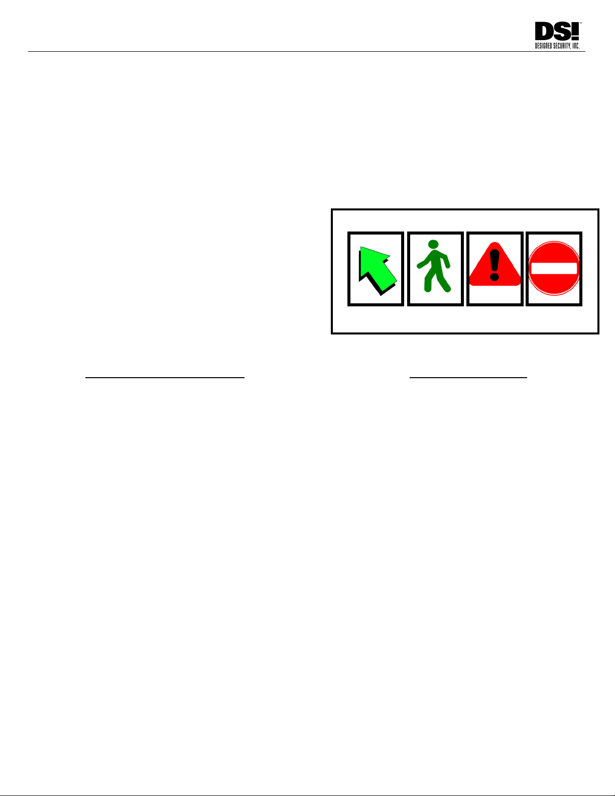
DISPLAY GRAPHICS
LANE READY PROCEED ALARM CLOSED
/BYPASS

20 INS9000 220523
DESIGNED SECURITY INC.
1402 Hawthorne Street Bastrop, Texas 78602
800-272-3555
Fax 512 321 9181
www.dsigo.com
Email: dsi@dsigo.com
GUARD/OPERATOR - OPTICAL TURNSTILE GUIDELINES
(LEAVE COPY AT GUARD OR OPERATOR DESK FOR REFERENCE)
Making an optical turnstile installation work well depends upon a number of factors being present.
Users must be provided adequate instruction. Written, and First-hand / One-on-one.
Users must know that a consequence to them exists for improper use, in order to
avoid abuse of the access control system. Without consequence, abuse will continue.
Guards must be knowledgeable in proper operation of the turnstiles, and be able to
effectively provide training to new or errant Users.
Guards must have an established policy and the authority to act on any Security
violation.
TRAINING USERS
Optimally, all Users need to be provided with a written instruction, and, be shown at least one time, one-on-
one, how to properly use the turnstile.
Instruction should include having the User identify the Reader location and be asked to explain to the
instructor what is expected of the User as they approach and use the lane.
The Users need to know that they are to always AVOID touching the barriers, except in an emergency.
This is a violation. IF THE USER TOUCHES THE BARRIERS, THEY SHOULD VISIT THE GUARD.
NOTE: The single most frequent violation, and cause of abuse, results from Users “pushing through” the
barriers. It is important that the User be trained to NEVER touch the barriers, they are automatic.
GUARD TRAINING AND AUTHORITY
The Guard MUST have the authority to stop Users who have violated a lane. Even Free Exiting Users who
cause an alarm should be encouraged to use the lane properly through some consequence to their action
after causing a violation. Without consequence, the User will continue to abuse the Security system.
TIP: Some of our customers get good results by having their Guard call an errant User over to the desk and verify
the User’s ID. This inconvenience to the User’s routine encourages them to use the lane properly and to avoid
causing alarms. This also provides the Guard an opportunity to help the User learn how to use the turnstile.
It is important that the Guard deal with the User from a frame of mind of “What can I do to help you learn how
to use the Security system and avoid causing alarms?”
Having copies of the User Instructions available to give users is suggested. Taking time to lead the user
through the process will also help build rapport and reinforce that the relationship between the Guard and the
User is complementary rather than adversarial.
If you have questions, or would like further assistance drawing from over a decade of experience with Optical
Turnstiles, please contact DSI Customer Support at 800 272 3555.
Table of contents
Other Detex Turnstile manuals


Popular Turnstile manuals by other brands

ZKTeco
ZKTeco FHT2300 installation guide

digicon
digicon dGate AW product manual

Magnetic Autocontrol
Magnetic Autocontrol MPH 112 operating instructions

Ier
Ier Automatic Systems PNG3 Series installation manual

digicon
digicon Turnstile Duo product manual

BOON EDAM
BOON EDAM Turnlock 100 Safety and operation instructions


